JOFGMORArctic Cat N-Touch Communication System
Radio Sound Inc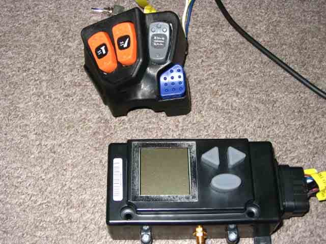
Click to zoom
Application Details
- Equipment Class
- FRB - Part 95 Family Radio Base Transmitter
- Date of Grant
- Jun 28, 2005
- Application Purpose
- Original Equipment
- Date of Application
- Jun 28, 2005
- Equipment Note
- Arctic Cat N-Touch Communication System
- Frequency Range
- 462.56250000 - 462.72500000
- Company
- Radio Sound Inc
- Country
- United States
Documents & Files
Document Text
Text extracted from the exhibit documents filed with the FCC. Open a document above to read the original.
Users Manual
1 FCC ID JOFGMOR IC: 5855A-GMOR User Instructions ARCTIC CAT N-TOUCH COMMUNICATION SYSTEM Table of Contents: Introduction Page 2 Safety and General Information Page 2 Transmit Procedure Antenna Information General Use Information Blasting and Potentially Explosive Areas Licensing Requirements Page 3 GMRS Frequency Allocation Page 3 Communication System Overview Page 4 Communication System Display Overview Page 5 Communication System Set-up Instructions Page 6 Adjusting the Rider’s Volume Channel Selection Interference Elimination Code Selection Adjusting the Passenger’s Volume Muting the Communication System Communication System Set-up Instructions Continued Page 7 Intercom and Voice Activation Sensitivity (VOX) Adjusting the Voice Activation Sensitivity (VOX) Using Your Communication System Page 7 Transmit and Receive Information Getting Started with Transmitting and Receiving Auxiliary Input Jack 2 FCC ID JOFGMOR IC: 5855A-GMOR User Instructions Introduction to Your Arctic Cat N-Touch Communication System: Your snowmobile is equipped with a personal two-way radio communication system and intercom. This will enable you to keep in touch with other riders and to easily talk with your passenger. The communication system uses General Mobile Radio Service (GMRS) radio frequencies. GMRS is a land- mobile radio service available for short-distance two-way communications to facilitate the activities of an adult individual and his or her family members. The radio communication system on your snowmobile has an output power of two watts. Distance performance is dependent on the terrain, weather conditions and the antenna system. This system requires professional installation by an authorized Arctic Cat dealership. Repair and service should also be performed by your dealer. Note: For optimal performance it is important to follow the Set-up Instructions included in this book. Safety and General Information: Read this information before using your radio for safe and efficient operation. Transmit Procedure: Your snowmobile has been equipped with a 2-way radio, meaning it can both transmit and receive radio frequency (RF) signals. To reduce your exposure to the RF signals, it is recommended that you do not transmit more than 50% of the time. By only using the transmission 50% of the time, you will be in compliance with the general population and uncontrolled environment exposure standards. Antenna Information: The supplied antenna meets important product performance specifications and is an integral part of both FCC and Industry Canada compliance. Changing or modifying the antenna in any way could potentially damage the radio and violate FCC and/or Industry Canada regulations. Avoid contact with the antenna when transmitting. This device meets the RF guideline FCC/OET 65 and Canadian health code 6 for mobile devices, which assumes installation provides an antenna distance of at least 20cm (8”) from users and others. General Use Information: Laws regarding the use of radios vary from state to state in the United States, and in Canada. Check the laws in the areas where you ride, and obey them. It is recommended that you give full attention to riding while using your radio. If the riding conditions dictate, pull over to make and receive transmissions. Blasting and Potentially Explosive Areas: Do not use your radio in blasting zones or potentially explosive areas. These areas are generally marked with signs reading “ TURN OFF 2-WAY RADIO”, “BLASTING AREA”, “BLASTING ZONE” or “POTENTIALLY EXPLOSIVE AREA”. Using your communication systems in these areas can interfere with their operations. 3 FCC ID JOFGMOR IC: 5855A-GMOR User Instructions Licensing Requirements: The Federal Communications Commission (FCC) requires General Mobile Radio Service (GMRS) operators to obtain a license prior to operating GMRS radios. Both form 605 and 159 are required for the license. These forms can be requested from the FCC at the following numbers: For Fax Requests: 1-202-418-0177 Mail Requests 1-800-418-3676 FCC GMRS License Questions 1-888-225-5322 The forms can also be completed online at www.fcc.gov . Modifications to this product by persons not deemed qualified by the manufacturer will void the warranty and may void the user’s FCC license to use this product. No license is required for use in Canada. GMRS Frequency Allocation: It is possible to use a GMRS radio from another manufacturer to communicate with your Arctic Cat communication system. The user manual for the other product can be compared for channel compatibility by using the frequency chart below. For example, the Arctic Cat radio uses channel 1 to transmit at 462.5625 MHz, while some handheld radios may use channel 15 for 462.5625. The following chart shows the signal frequency for transmitting (TX) and receiving (RX) radio frequencies. Channel TX/RX Frequency (MHz) 1 462.5625 2 462.5875 3 462.6125 4 462.6375 5 462.6625 6 462.6875 7 462.7125 8 462.5750 9 462.6250 10 462.6750 11 462.5500 12 462.6000 13 462.6500 14 462.7000 15 462.7250 4 FCC ID JOFGMOR IC: 5855A-GMOR User Instructions ARCTIC CAT N-TOUCH COMMUNICATION SYSTEM MODE: Allows you to cycle through the functions of the communication system. The functions in order are as follows: Channel, Code, Front/Rear Volume (F/R), Voice Activation Sensitivity (VOX). After a few seconds of inactivity the mode will revert back to volume. UP: This button controls volume up. When you are in a different mode it will allow you to change the selection. DOWN: This button controls volume down. When you are in a different mode it will allow you to change the selection. 5 FCC ID JOFGMOR IC: 5855A-GMOR User Instructions Communication System Display 1. Mute: This icon appears when mute is activated from the handle bar control. You can not receive or hear any audio. 2. Volume Level Indicator Graph: This icon is activated for rider and passenger headset volume adjustment. 3. Front/Rear Headset Volume: The passenger headset volume can…
Text truncated - open the document above for the full version.
Cover Letter(s)
Attention: Application Examiner Re: Request for confidentiality Applicant: Radio Sound, Inc FCC ID: JOFGMOR ICID: 5855A-GMOR To whom it may concern, Permanent Confidentiality Request is hereby submitted by Radio Sound, Inc to withhold permanently from public review certain portions of the application for equipment certification for the referenced FCC identifiers. This request for confidentiality is made pursuant to 47 CFR 0.457(d) and 0.459 of the FCC Rules. In particular, the following sections of the application are to be kept permanently confidential: • Schematics • Detailed Block diagrams • Detailed Operational/Functional Description • Tune up procedure • Parts list Rationale for request for confidentiality: Radio Sound, Inc. has invested considerable time and materials in research and development to produce the referenced product. Disclosure of the permanently confidential portions of this application to competitors would not only give them significant competitive advantages in developing similar products, but would also disclose successful implementation of unpublished, leading edge technology developed by us. Sincerely, 1(1)
External Photos
Figure 1: GMRO with Wiring Ha rness and Handlebar Controls Figure 2: GMRO with Handlebar Controls Figure 3: Back Side of GMRO Figure 4: GMRO Wiring Harness Side Figure 5: GMRO Antenna Connection Side Figure 6: Sleeve Dipole Antenna with Connecting Cable
Internal Photos
Figure 1: GMRO Taken Apart Figure 2: GMRO Taken Apart #2 Figure 3: Audio Board Front Figure 4: Audio Board Back Figure 5: Display Board Front Figure 6: Display Board Back Figure 7: Transmitter Board Front Figure 8: Transmitter Board Back
Test Report
This report may be reproduced only with the written permission of Intertek and if reproduced must be reproduced in its entirety. This report must not be used to claim product endorsement by NVLAP or any agency of the U.S. Government. The results contained in this report were derived from measurements performed on the identified test samples. Any implied performance of other samples based on this report is dependent on the representative adequacy of the samples tested. TEST REPORT Report Number: 3074983-001 Project Number: 3074983 6/28/2005 Evaluation of the GMRS Transceiver Model Number: GMOR FCC ID: JOFGMOR ICID: 5855A-GMOR FCC Part 95 Subpart A and RSS-210, Issue 5: Amendment No. 4 For Radio Sound Test Performed by: Test Authorized by: Intertek 731 Enterprise Drive Lexington, KY 40510 Radio Sound 1713 Cobalt Drive Louisville, KY 40299 Prepared By:_______________________________Date:____6/28/2005________ Jason Centers, Project Engineer Approved By:______________________________Date:____6/28/2005_________ Bryan C. Taylor, EMC Team Leader Intertek 731 Enterprise Drive, Lexington, KY 40510 731 Enterprise Drive, Lexington KY 40510 Evaluation For:Radio Sound FCC ID: JOFGMOR Model No: GMOR ICID: 5855A-GMOR Report Number: 3074983-001 Page 2 of 35 FCC Part 95A and RSS-210 Evaluation TABLE OF CONTENTS 1 EXECUTIVE SUMMARY................................................................................................................. 4 2 JOB DESCRIPTION .......................................................................................................................... 5 2.1 GENERAL INFORMATION................................................................................................................ 5 2.2 EQUIPMENT UNDER TEST (EUT) .................................................................................................... 6 2.2.1 Cables associated with EUT ................................................................................................... 6 2.2.2 Mode(s) of operation............................................................................................................... 6 3 TEST FACILITY................................................................................................................................ 7 3.1 TEST EQUIPMENT............................................................................................................................ 8 4 TRANSMITTED FREQUENCIES ................................................................................................... 9 4.1 CRITERIA........................................................................................................................................ 9 4.2 TEST PROCEDURE........................................................................................................................... 9 4.3 BLOCK DIAGRAM........................................................................................................................... 9 4.4 TEST RESULTS.............................................................................................................................. 10 5 RF POWER OUTPUT ..................................................................................................................... 11 5.1 CRITERIA...................................................................................................................................... 11 5.2 TEST PROCEDURE FOR CONDUCTED OUTPUT POWER.................................................................. 11 5.3 BLOCK DIAGRAM FOR CONDUCTED OUTPUT POWER.................................................................. 11 5.4 TEST PROCEDURE FOR RADIATED OUTPUT POWER..................................................................... 12 5.5 BLOCK DIAGRAM FOR RADIATED OUTPUT POWER...................................................................... 12 5.6 TEST RESULTS.............................................................................................................................. 13 6 MAXIMUM PERMISSIBLE EXPOSURE (MPE) CALCULATIONS ...................................... 14 6.1 CRITERIA...................................................................................................................................... 14 6.2 TEST PROCEDURE......................................................................................................................... 14 6.3 TEST RESULTS.............................................................................................................................. 14 7 MODULATION CHARACTERISTICS ........................................................................................ 15 7.1 CRITERIA...................................................................................................................................... 15 7.2 TEST PROCEDURE......................................................................................................................... 15 7.3 BLOCK DIAGRAM......................................................................................................................... 15 7.4 TEST RESULTS.............................................................................................................................. 16 8 OCCUPIED BANDWIDTH.............................................................................................................19 8.1 CRITERIA...................................................................................................................................... 19 731 Enterprise Drive, Lexington KY 40510 Evaluation For:Radio Sound FCC ID: JOFGMOR Model No: GMOR ICID: 5855A-GMOR Report Number: 3074983-001 Page 3 of 35 FCC Part 95A and RSS-210 Evaluation 8.2 TEST PROCEDURE......................................................................................................................... 19 8.3 BLOCK DIAGRAM............................................................................................…
Text truncated - open the document above for the full version.
Test Setup Photos
Figure 1: Conducted Testing Figure 2: Radiated Testing Figure 3: Radiated Testing #2 Figure 4: Substitution Measurements
Contact Information
Applicant
Donald Tilley
Technical Contact
Radio Sound IncDonald R Tilley
[email protected](502) 515-0205
1713 Cobalt DR · Louisville, Kentucky · United States
Non-Technical Contact
Radio Sound IncDonald R Tilley
[email protected](502) 515-0205
Test Firm
Intertek Testing Services NA Inc.Bryan Taylor
Technical Specifications
| # | Rule Parts | Frequency Range | Power Output | Emission | Tolerance |
|---|---|---|---|---|---|
| 1 | 95A | 462.5625 MHz - 462.725 MHz | 1.95 W | 5K4F3E | 0.0002500000 % |
Other Applications from Radio Sound Inc
JOFRS2025X
Jul 24, 2014CB radio transceiver module
Equipment Class
TNB - Licensed Non-Broadcast Station Transmitter
JOFRS51033
Aug 28, 2012CB RADIO TRANSCEIVER
Equipment Class
TNB - Licensed Non-Broadcast Station Transmitter
JOFRS20250
Mar 17, 2008Radio Sound Model RS20250
Equipment Class
TNB - Licensed Non-Broadcast Station Transmitter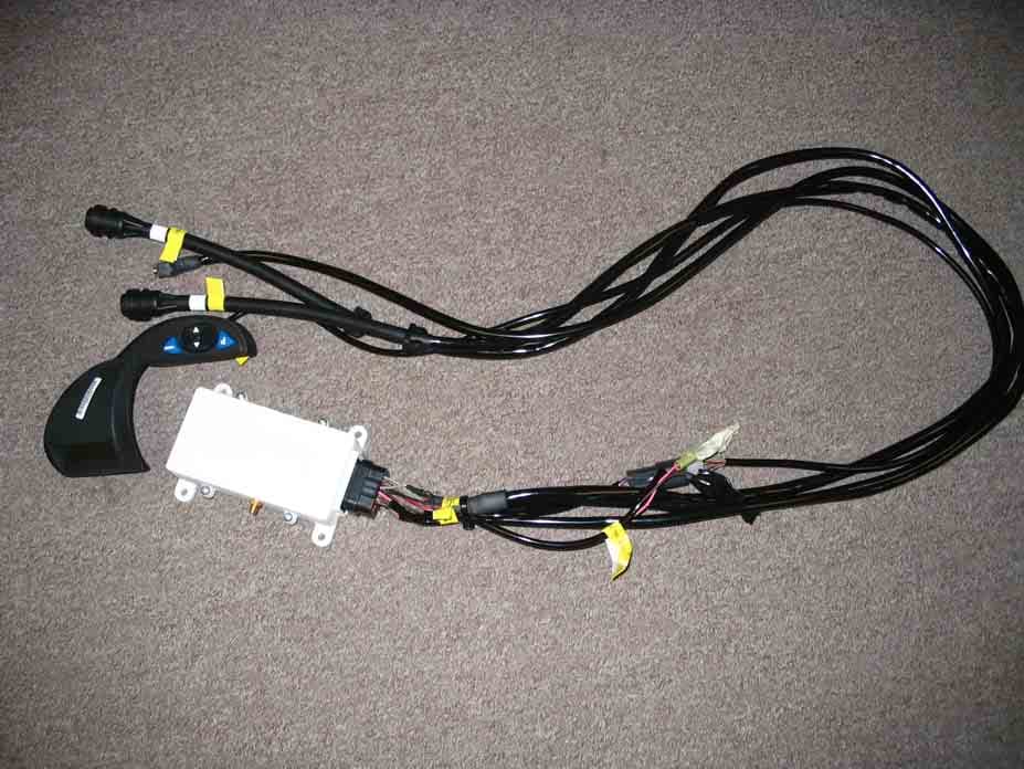
JOFGMSH
Jun 28, 2005N-TOUCH GMRS Communication System
Equipment Class
FRB - Part 95 Family Radio Base Transmitter
JOFRS9803UDA
Feb 02, 2004Integrated Motorcycle 40 Channel AM CB Transceiver
Equipment Class
TNB - Licensed Non-Broadcast Station Transmitter