JOFRS20250Radio Sound Model RS20250
Radio Sound Inc
Click to zoom
Application Details
- Equipment Class
- TNB - Licensed Non-Broadcast Station Transmitter
- Date of Grant
- Mar 17, 2008
- Application Purpose
- Original Equipment
- Date of Application
- Mar 17, 2008
- Equipment Note
- Radio Sound Model RS20250
- Frequency Range
- 26.96500000 - 27.40500000
- Company
- Radio Sound Inc
- Country
- United States
Documents & Files
Document Text
Text extracted from the exhibit documents filed with the FCC. Open a document above to read the original.
Users Manual
SUNDAY SILENCE CB RADIO OPERATING INSTRUCTIONS 1. Turning power on and off. a. Press the CB button on the switch panel located on the fuel tank to turn on the receiver. b. When the CB button on the switch panel is pressed and held down, a beep is heard and the power is turned off. c. Each time the CB button is pressed momentarily, the CB transceiver sound is switched between the speaker and the headset. 2. Selecting Channel a. Press the CB-CH handlebar switch upwards or downwards with your thumb to change channels. When the switch is pressed upwards or downwards continuously, a beep is heard and channels are changed continuously. There are a total of 40 channels. b. Below is a table of CB frequencies and corresponding channel numbers. CH MHz CH MHz CH MHz CH MHz 1 26.965 11 27.085 21 27.215 31 27.315 2 26.975 12 27.105 22 27.225 31 27.325 3 26.985 13 27.115 23 27.255 33 27.335 4 27.005 14 27.125 24 27.235 34 27.345 5 27.015 15 27.135 25 27.245 35 27.355 6 27.025 16 27.155 26 27.265 36 27.365 7 27.035 17 27.165 27 27.275 37 27.375 8 27.055 18 27.175 28 27.285 38 27.385 9 27.065 19 27.185 29 27.295 39 27.395 10 27.075 20 27.205 30 27.305 40 27.405 3. Adjusting Volume a. Press the CB-VOL switch upwards or downwards with your thumb to raise or lower the volume. When the switch is pressed upwards or downwards continuously, a beep is heard and the volume is raised or lowered continuously. b. The display indicates the current CB-VOL in numbers, for example 20. Maximum volume is 20 and minimum volume is 00. The CB transceiver volume can be set independently of the other audio system functions. 4. Transmitting a. Press and hold the TALK switch to start transmission. The other audio functions are muted during transmission to make sure that communications with the other party are not drowned out. b. When a TALK switch for the passenger is used, pressing the passenger TALK switch will allow the passenger to transmit. c. Both rider and passenger voices are transmitted whenever either TALK switch is pressed. 5. Adjusting Squelch a. If another CB operator using the same channel is nearby, interference will occur. To cancel such interference, set the squelch level slightly lower than the signal strength you are using and the transceiver will receive only the signal from the other CB operator you wish to hear. b. A squelch setting of 20 will only receive extremely strong signals while a squelch setting of 01 will produce noise at all times even when not actual CB signal is present. c. Press the CB-SQL switch upwards or downwards to change the squelch level. When the switch is pressed upwards or downwards continuously, a beep is heard and the squelch level is changed continuously. d. Maximum squelch level is 20 the minimum level is 01.
Users Manual
(d) If a Federal court finds that you have willfully and knowingly violated any provision of the Communications Act, you may be fined up to $10,000 or you may be imprisoned for one year, or both. (See section 501 of the Communications Act.) [48 FR 24894, June 3, 1983, as amended at 57 FR 40343, Sept. 3, 1992] Sec. 95.422 (CB Rule 22) How do I answer correspondence from the FCC? (a) If it appears to the FCC that you have violated the Communications Act or these rules, the FCC may send you a discrepancy notice. (b) Within the time period stated in the notice, you must answer with: (1) A complete written statement about the apparent discrepancy; (2) A complete written statement about any action you have taken to cor- rect the apparent violation and to pre- vent it from happening again; and (3) The name of the person operat- ing at the time of the apparent violation. (c) If the FCC sends you a letter asking you questions about your CB radio station or its operation, you must answer each of the questions with a complete written statement within the time period stated in the letter. (d) You must not shorten your answer by references to other commu- nications or notices. (e) You must send your answer to the FCC office which sent you the notice. (f) You must keep a copy of your answer in your station records. (See CB Rule 27, Sec. 95.427.) Sec. 95.423 (CB Rule 23) What must I do if the FCC tells me that my CB station is causing interference? (a) If the FCC tells you that your CB station is causing interference for tech- nical reasons you must follow all instructions in the official FCC notice. (This notice may require you to have technical adjustments made to your equipment.) (b) You must comply with any restricted hours of CB station operation which may be included in the official notice. Sec. 95.424 (CB Rule 24) How do I have my CB station transmitter serv- iced? (a) You may adjust an antenna to your CB transmitter and you may make radio checks. (A radio check means a one way transmission for a short time in order to test the transmitter.) (b) You are responsible for the proper operation of the station at all times and are expected to provide for observations, servicing and mainte- nance as often as may be necessary to ensure proper operation. You must have all internal repairs or internal adjustments to your CB transmitter made in accordance with the Technical Regulations (see subpart E). The inter- nal repairs or internal adjustments should be performed by or under the immediate supervision and responsibil- ity of a person certified as technically qualified to perform transmitter mainte- nance and repair duties in the private land mobile services and fixed services by an organization or committee repre- sentative of users in those services. (c) Except as provided in paragraph (d) of this section, each internal repair and each internal adjustment of a CB transmitter in which signals are trans- mitted must be made using a nonradi- ating (“dummy”) antenna. (d) Brief test signals (signals not longer than one minute during any five minute period) using a radiating anten- na may be transmitted in order to: (1) Adjust an antenna to a transmit- ter; (2) Detect or measure radiation of energy other than the intended signal; or (3) Tune a receiver to your CB transmitter. (Secs. 4(i) and 303(r), Communications Act of 1934, as amended, 47 U.S.C. 154(i) and 303(r), and sec. 553 of the Administrative Procedures Act, 5 U.S.C. 553) [48 FR 24894, June 3, 1983, as amended at 49 FR 20673, May 16, 1984] Sec. 95.425 (CB Rule 25) May I make any changes to my CB station trans- mitter? (a) You must not make or have any one else make any internal modifica- tion to your CB transmitter. (b) Internal modification does not include: (1) Repair or servicing of a CB sta- tion transmitter (see CB Rule 24, Sec. 95.424); or (2) Changing plug-in modules which were certificated as part of your CB transmitter. (c) You must not operate a CB transmitter which has been modified by anyone in any way, including modifica- tion to operate on unauthorized fre- quencies or with illegal power. (See CB Rules 9 and 11, Sec. Sec. 95.409 and 95.411.) [48 FR 24894, June 3, 1983, as amended at 63 FR 36610, July 7, 1998] Sec. 95.426 (CB Rule 26) Do I have to make my CB station available for inspection? (a) If an authorized FCC represen- tative requests to inspect your CB sta- tion, you must make your CB station and records available for inspection. (b) A CB station includes all of the radio equipment you use. Sec. 95.427 (CB Rule 27) What are my station records? Your station records include the fol- lowing documents, as applicable. (a) A copy of each response to an FCC violation notice or an FCC letter. (See CB Rule 22, Sec. 95.422.) (b) Each written permission received from the FCC. (See CB Rule 19, Sec. 95.419.) Sec. 95.428 (CB Rule 28) How do I contact the FCC? (a) FCC National Call Center at 1- 888-225-5322. (b) FCC World Wide Web home- page: http://www.fcc.gov. (c) In writing, to FCC, Attention: CB, 1270 Fairfield Road, Gettysburg, PA 17325-7245. [63 FR 68976, Dec. 14, 1998] Page 5 Part 95 Subpart D Plain English Rules – Citizens Band Radio Service Prepared by the Federal Communications Commission Washington, D.C. (b) If your C/B station will be con- structed on an environmentally sensitive site, or will be operated in such a manner as to raise environmental problems, under Sec. 1.1307 of this chapter, you must provide an environmental assess- ment, as set forth in Sec. 1.1311 of this chapter, and undergo the environmental review, Sec. 1.1312 of this chapter, before commencement of construction. [48 FR 24894, June 3, 1983, as amended at 55 FR 20398, May 16, 1990] How To Operate a CB Station Sec. 95.407 (CB Rule 7) On what channels may I operate? (a) Your CB station may transmit only on the following channels (frequencies): \1\ See paragraph (b) of this section. (b) Channel 9 may be used only for emergency communications or for travel- er ass…
Text truncated - open the document above for the full version.
Cover Letter(s)
Radio Sound, Inc., 1713 Cobalt Drive, Louisville, Kentucky 40299-2449 Phone: (502) 267-6768 Fax: (502) 267-6794 Attention: Application Examiner Re: Request for confidentiality Applicant: Radio Sound, Inc. FCC ID: JOFRS20250 To whom it may concern, Permanent Confidentiality Request is hereby submitted by Radio Sound, Inc. to withhold permanently from public review certain portions of the application for equipment certification for the referenced FCC identifiers. This request for confidentiality is made pursuant to 47 CFR 0.457(d) and 0.459 of the FCC Rules. In particular, the following sections of the application are to be kept permanently confidential: • Schematics • Detailed Block diagrams • Detailed Operational/Functional Description • Tune up procedure • Parts list 1(2) 2(2) Short-term Confidentiality Request is hereby submitted by Radio Sound, Inc. to withhold from public review for a period of 45 days from the date of the Grant of Equipment Authorization and prior to marketing, certain portions of the application for equipment certification for the referenced FCC identifiers. This request for confidentiality is made pursuant to 47 CFR 0.457(d) and 0.459 of the FCC Rules. In particular, the following sections of the application are to be kept confidential for a period of 45 days from the date of Authorization: • Test setup photos • External photos • Internal photos • User manual Rationale for request for confidentiality: Radio Sound, Inc. has invested considerable time and materials in research and development to produce the referenced product. [Permanent confidentiality: Disclosure of the permanently confidential portions of this application to competitors would not only give them significant competitive advantages in developing similar products, but would also disclose successful implementation of unpublished, leading edge technology developed by us.][Short term confidentiality: Disclosure of the short-term confidential portions of this application during the period of importation and/or distribution would reveal key aspects of proprietary technology to competitors and diminish the value of our investment in research and development.] The fee for confidentiality has been submitted along with the fee for certification. If you have questions or need further information, please contact the undersigned. Sincerely, Donald R. Tilley _____________________________ Donald R. Tilley Executive Vice President Radio Sound, Inc.
Internal Photos
Component Side with Cables Attached Component Side with Cables Removed Back Side
Test Report
This report is for the exclusive use of Intertek's Client and is provided pursuant to the agreement between Intertek and its Client. Intertek's responsibility and liability are limited to the terms and conditions of the agreement. Intertek assumes no liability to any party, other than to the Client in accordance with the agreement, for any loss, expense or damage occasioned by the use of this report. Only the Client is authorized to copy or distribute this report and then only in its entirety. Any use of the Intertek name or one of its marks for the sale or advertisement of the tested material, product or service must first be approved in writing by Intertek. The observations and test results in this report are relevant only to the sample tested. This report by itself does not imply that the material, product, or service is or has ever been under an Intertek certification program. TEST REPORT Report Number: 3140979LEX-001 Project Number: 3140979 Evaluation of the CB Radio Model Number: RS20250 FCC ID: JOFS20250 ICID: 5855A-20250 FCC Part 2, 15 Subpart B, 95 Subpart D and RSS-136 Issue 5, October 2002 For Radio Sound Inc. Test Performed by: Test Authorized by: Intertek 731 Enterprise Drive Lexington, KY 40510 Radio Sound Inc. 1713 Cobalt Drive Louisville, KY 40299 Prepared By:_______________________________Date:____1/30/2008________ Bryan C. Taylor, EMC Team Leader Approved By:______________________________Date:____1/30/2008_________ Jason Centers, Senior Project Engineer Intertek 731 Enterprise Drive, Lexington, KY 40510 731 Enterprise Drive, Lexington KY 40510 Evaluation For:Radio Sound Inc. FCC ID: JOFS20250 Model No: RS20250 ICID: 5855A-20250 File: 3140979 Page 2 of 35 FCC and IC Evaluation TABLE OF CONTENTS 1 EXECUTIVE SUMMARY................................................................................................................. 4 2 JOB DESCRIPTION .......................................................................................................................... 5 2.1 CLIENT INFORMATION.................................................................................................................... 5 2.2 TEST PLAN REFERENCE:.................................................................................................................. 5 2.3 EQUIPMENT UNDER TEST (EUT) .................................................................................................... 6 2.4 SYSTEM SUPPORT EQUIPMENT....................................................................................................... 7 2.5 CABLES ASSOCIATED WITH EUT .................................................................................................... 7 2.6 JUSTIFICATION................................................................................................................................8 2.7 MODE(S) OF OPERATION................................................................................................................. 8 2.8 MODIFICATIONS REQUIRED FOR COMPLIANCE............................................................................... 8 2.9 RELATED SUBMITTAL(S) GRANTS.................................................................................................. 8 3 TEST FACILITY................................................................................................................................ 9 3.1 TEST EQUIPMENT.......................................................................................................................... 10 4 RF POWER OUTPUT ..................................................................................................................... 11 4.1 TEST PROCEDURE......................................................................................................................... 11 4.2 BLOCK DIAGRAM......................................................................................................................... 11 4.3 TEST RESULTS.............................................................................................................................. 11 5 MODULATION CHARACTERISTICS ........................................................................................ 12 5.1 TEST PROCEDURE......................................................................................................................... 12 5.2 BLOCK DIAGRAM......................................................................................................................... 12 5.3 TEST RESULTS.............................................................................................................................. 13 6 OCCUPIED BANDWIDTH.............................................................................................................15 6.1 TEST PROCEDURE......................................................................................................................... 15 6.2 BLOCK DIAGRAM......................................................................................................................... 15 6.3 TEST RESULTS.............................................................................................................................. 15 7 SPURIOUS EMISSIONS AT ANTENNA TERMINALS............................................................. 22 7.1 TEST PROCEDURE......................................................................................................................... 22 7.2 BLOCK DIAGRAM......................................................................................................................... 22 7.3 TEST RESULTS.............................................................................................................................. 23 8 FIELD STRENGTH OF SPURIOUS RADIATION ..................................................................... 24 8.1 TEST PROCEDURE.................................................................................................................…
Text truncated - open the document above for the full version.
Test Setup Photos
Conducted Testing Radiated Testing, Front Side Radiated Testing, Back Side Radiated Testing Below 30MHz Usin g Magnetic Field Loop Antenna
Contact Information
Applicant
Donald Tilley
Technical Specifications
| # | Rule Parts | Frequency Range | Power Output | Emission | Tolerance |
|---|---|---|---|---|---|
| 1 | 95D | 26.965 MHz - 27.405 MHz | 3.94 W | 6K00A3E | 0.0050000000 % |
Other Applications from Radio Sound Inc
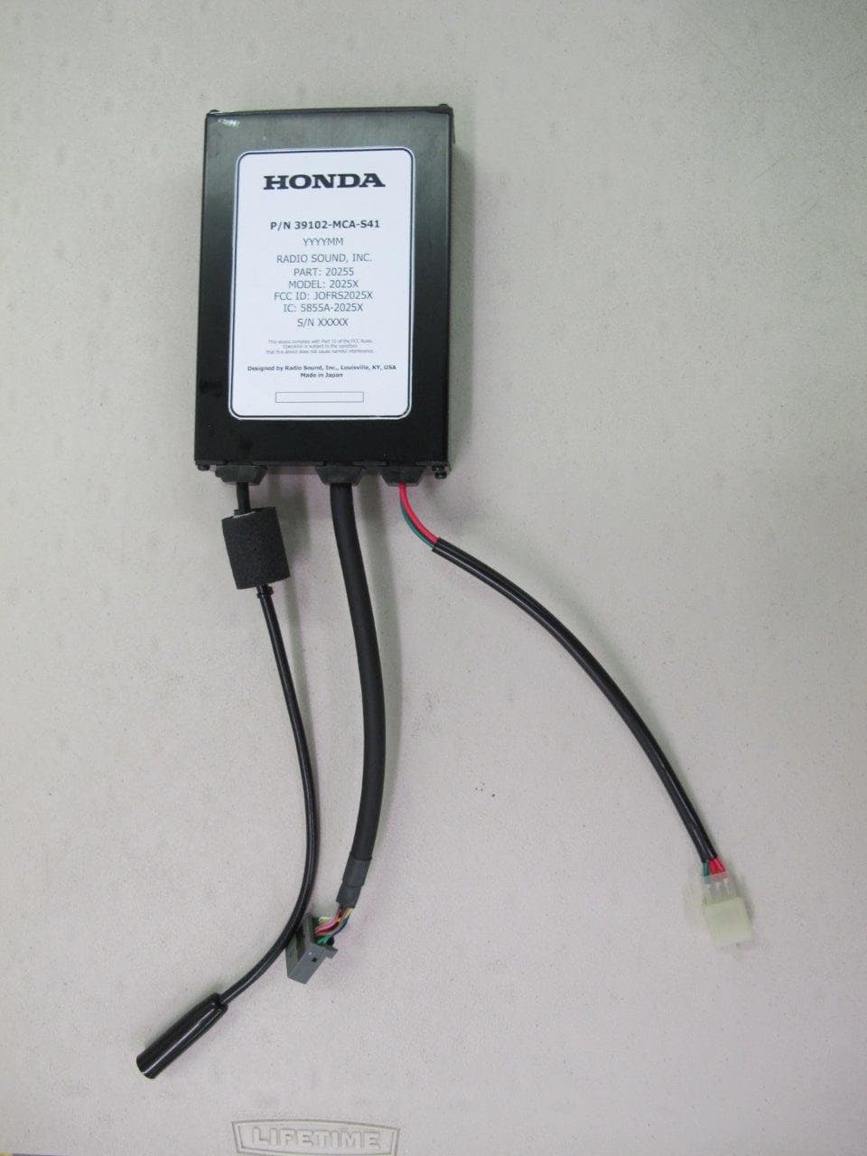
JOFRS2025X
Jul 24, 2014CB radio transceiver module
Equipment Class
TNB - Licensed Non-Broadcast Station Transmitter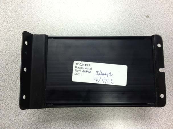
JOFRS51033
Aug 28, 2012CB RADIO TRANSCEIVER
Equipment Class
TNB - Licensed Non-Broadcast Station Transmitter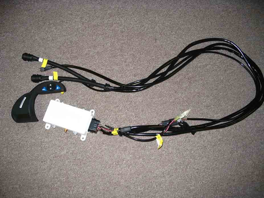
JOFGMSH
Jun 28, 2005N-TOUCH GMRS Communication System
Equipment Class
FRB - Part 95 Family Radio Base Transmitter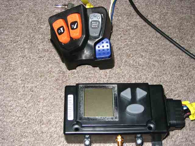
JOFGMOR
Jun 28, 2005Arctic Cat N-Touch Communication System
Equipment Class
FRB - Part 95 Family Radio Base Transmitter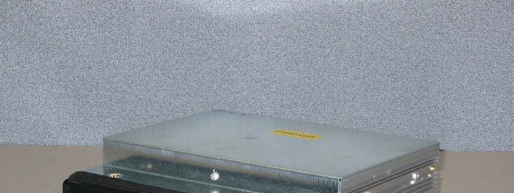
JOFRS9803UDA
Feb 02, 2004Integrated Motorcycle 40 Channel AM CB Transceiver
Equipment Class
TNB - Licensed Non-Broadcast Station Transmitter