JOFRS2025XCB radio transceiver module
Radio Sound Inc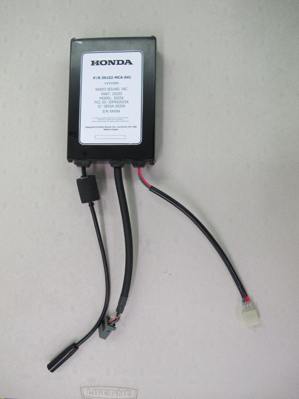
Click to zoom
Application Details
- Equipment Class
- TNB - Licensed Non-Broadcast Station Transmitter
- Date of Grant
- Jul 24, 2014
- Application Purpose
- Original Equipment
- Date of Application
- Jul 24, 2014
- Equipment Note
- CB radio transceiver module
- Frequency Range
- 26.96500000 - 27.40500000
- Company
- Radio Sound Inc
- Country
- United States
Documents & Files
Document Text
Text extracted from the exhibit documents filed with the FCC. Open a document above to read the original.
Users Manual
USER'S GUIDE Motorcycle P/N: 87947-MCA-R10 2 This CB radio complies with applicable FCC Rules and Regulations.* WARNING Never use the CB radio in such as way that could be dangerous while • riding, such as taking your hands off the handlebars to operate the controls. Never replace parts or disassemble/modify the CB radio in a way that • could impair its original features and/or violate Federal Communications Commission (FCC) rules and regulations. The Citizens Band (CB) Radio Service is under the jurisdiction of the • FCC. Any alterations such as replacing any parts in the CB radio that alter the performance of the unit’s original FCC equipment authorization are strictly prohibited. Any changes or modifications not expressly approved the par ty • responsible for compliance could void the user’s authority to operate the equipment. Carefully read Part 95 of the FCC Rules and Regulations before using the • device. This device complies with part 15 of the FCC rules. Operation is subject to the condition that this device does not cause harmful interference. This CB radio has been approved by the Federal Communications • Commission (FCC) in the U.S.A. and Industry Canada (IC) in Canada, and the FCC ID and IC numbers are shown on the label. An individual license is not required in either the U.S.A. or Canada. Please read the rules for operating a CB transmitter carefully. Carefully read the User’s Guide and Citizens Band Radio service rules • before operating the CB radio. Learn and observe all the rules. 3 Introduction Congratulations on your purchase of this Honda Genuine Accessory. This CB radio will enhance the enjoyment of riding your motorcycle. Before using this CB radio, read the User's Guide carefully. Following the instructions • in the guide will allow you to experience the full functionality of the radio. Store this guide on your motorcycle so that you can refer to it wherever required. • Make sure you read and understand the guide before you start using the transceiver as incorrect operation could be dangerous. You will be given a completed Warranty Card by the dealer who sold you your CB • radio. Check the details of the Warranty Card and keep it with the User's Guide. Notes on Safety Explanation of safety labels, symbols, and instructions The User’s Guide should be kept with the motorcycle at all times. Listed below are examples of important safety labels, symbols, and instructions used in the User’s Guide indicating various levels of risk if the instructions are not properly followed. Guide for Notes and Tips NOTE : This sign gives notes and helpful information on the use of the CB radio. TIP(*): This sign gives additional information to the content. WARNING You CAN be KILLED or SERIOUSLY HURT if you don’t follow these instructions. Classification of Other Symbols This symbol indicates “Do not” with the detail depicted in the symbol (in this example, it means do not disassemble). This symbol indicates to pay close attention to the procedure. CAUTION You CAN be HURT if you don’t follow these instructions. 4 Notes to Users WARNING While riding, do not operate any switches other than the TALK switch. Operating any switch, other than the TALK switch, can interfere with the rider’s ability to control the handlebars, which can cause instability that could lead to a crash. Always adjust the settings of the CB radio before riding. Do not operate the CB radio with your hand away from the handlebar. Do not use the CB radio under dangerous traffic conditions. Only use the CB radio when traffic and road conditions are such that it is safe to do so. NOTICE Do not expose the CB radio to excessive amounts or a forceful flow of water. When washing the motorcycle, do not spray water on the CB radio with a hose. The CB radio is designed to be water resistant and moisture proof, and should withstand riding in normal rainy conditions. If exposed to more severe conditions, water or moisture might enter the device and could result in failure. Do not use in a damaged condition. Do not use the CB radio if the casing is physically damaged. The CB radio’s water resistant and moisture proof capabilities will be impaired and which could lead to a failure. 5 NOTE Use with the engine running. If the CB radio is used with the engine stopped, the battery voltage may drop and the engine may not start. Do not disassemble/modify the CB radio. The CB radio is built with precision electronic parts. Do NOT disassemble at any time. Doing so will void the Warranty and violates the mandated usage rules. CAUTION Do not raise the volume to an excessive level. To help prevent potentially dangerous situations while riding, keep the volume to a level where you can still hear surrounding noises. Listening at an excessive volume can damage your hearing. 6 Notes for Installation NOTICE Refer to the Installation Instructions for proper installation. Do not use a power source other than 12V. The CB radio is designed only for a 12V DC negative ground motorcycle. Do not connect to another voltage power source. Mount the controls in a location where you can reach them with your hands on the handlebar. To prevent a dangerous riding situation, mount the controls in a location where they do not inhibit your ability to control the motorcycle, and where you can operate the TALK switch with your hands on the handlebar. Use the Honda genuine CB antenna. There may be some CB radio interference if a non- genuine Honda antenna is used. Always use the specified fuse rating. Not doing so may cause damage to the CB radio unit. 7 Introduction ..................................................................................3 Notes on Safety ...........................................................................3 Notes to Users .............................................................................4 FEATURES ...................................................................................8 PACKAGE LIST ................................…
Text truncated - open the document above for the full version.
External Photos
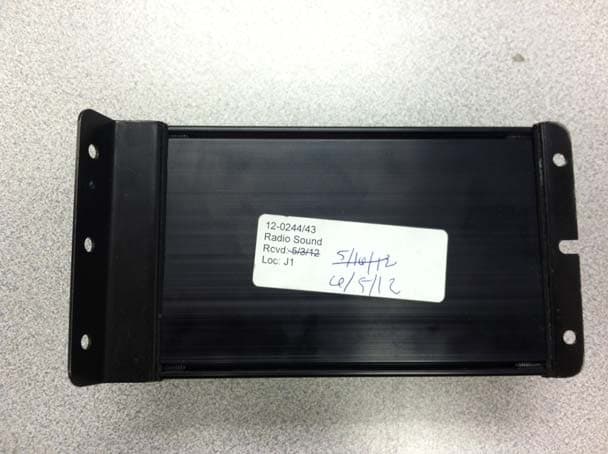
U.S. Tech Test Report: FCC Part 95, IC RSS-236 FCC ID: JOFRS2025X IC: 5855A-2025X Report Number: 14-0096 & 14-0097 Issue Date: July 26, 2014 Customer: Radio Sound Inc. Model: RS2025X Page 1 of 6 Annex 3 - External Photographs Figure 1- Top View U.S. Tech Test Report: FCC Part 95, IC RSS-236 FCC ID: JOFRS2025X IC: 5855A-2025X Report Number: 14-0096 & 14-0097 Issue Date: July 26, 2014 Customer: Radio Sound Inc. Model: RS2025X Page 2 of 6 Figure 2- Side 1 U.S. Tech Test Report: FCC Part 95, IC RSS-236 FCC ID: JOFRS2025X IC: 5855A-2025X Report Number: 14-0096 & 14-0097 Issue Date: July 26, 2014 Customer: Radio Sound Inc. Model: RS2025X Page 3 of 6 Figure 3- Side 2 U.S. Tech Test Report: FCC Part 95, IC RSS-236 FCC ID: JOFRS2025X IC: 5855A-2025X Report Number: 14-0096 & 14-0097 Issue Date: July 26, 2014 Customer: Radio Sound Inc. Model: RS2025X Page 4 of 6 Figure 4- Bottom View U.S. Tech Test Report: FCC Part 95, IC RSS-236 FCC ID: JOFRS2025X IC: 5855A-2025X Report Number: 14-0096 & 14-0097 Issue Date: July 26, 2014 Customer: Radio Sound Inc. Model: RS2025X Page 5 of 6 Figure 5- End Cap U.S. Tech Test Report: FCC Part 95, IC RSS-236 FCC ID: JOFRS2025X IC: 5855A-2025X Report Number: 14-0096 & 14-0097 Issue Date: July 26, 2014 Customer: Radio Sound Inc. Model: RS2025X Page 6 of 6 Figure 6- Cable Ports
ID Label/Location Info
U.S. Tech Test Report: FCC Part 95, IC RSS-236 FCC ID: JOFRS2025X IC: 5855A-2025X Report Number: 14-0096 & 14-0097 Issue Date: June 26, 2014 Customer: Radio Sound Inc. Model: RS2025X Page 1 of 1 Sample Label:
Internal Photos
U.S. Tech Test Report: FCC Part 95, IC RSS-236 FCC ID: JOFRS2025X IC: 5855A-2025X Report Number: 14-0096 & 14-0097 Issue Date: June 26, 2014 Customer: Radio Sound Inc. Model: RS2025X Page 1 of 8 Annex 2 - Internal Photographs Figure 1. Circuit Board Top with Connections U.S. Tech Test Report: FCC Part 95, IC RSS-236 FCC ID: JOFRS2025X IC: 5855A-2025X Report Number: 14-0096 & 14-0097 Issue Date: June 26, 2014 Customer: Radio Sound Inc. Model: RS2025X Page 2 of 8 Figure 2. Circuit Board Side 1 U.S. Tech Test Report: FCC Part 95, IC RSS-236 FCC ID: JOFRS2025X IC: 5855A-2025X Report Number: 14-0096 & 14-0097 Issue Date: June 26, 2014 Customer: Radio Sound Inc. Model: RS2025X Page 3 of 8 Figure 3. Side 2, Heat Sink U.S. Tech Test Report: FCC Part 95, IC RSS-236 FCC ID: JOFRS2025X IC: 5855A-2025X Report Number: 14-0096 & 14-0097 Issue Date: June 26, 2014 Customer: Radio Sound Inc. Model: RS2025X Page 4 of 8 Figure 4. Side 2 U.S. Tech Test Report: FCC Part 95, IC RSS-236 FCC ID: JOFRS2025X IC: 5855A-2025X Report Number: 14-0096 & 14-0097 Issue Date: June 26, 2014 Customer: Radio Sound Inc. Model: RS2025X Page 5 of 8 Figure 5. Side 2 U.S. Tech Test Report: FCC Part 95, IC RSS-236 FCC ID: JOFRS2025X IC: 5855A-2025X Report Number: 14-0096 & 14-0097 Issue Date: June 26, 2014 Customer: Radio Sound Inc. Model: RS2025X Page 6 of 8 Figure 6. Bottom U.S. Tech Test Report: FCC Part 95, IC RSS-236 FCC ID: JOFRS2025X IC: 5855A-2025X Report Number: 14-0096 & 14-0097 Issue Date: June 26, 2014 Customer: Radio Sound Inc. Model: RS2025X Page 7 of 8 Figure 7. Power Transistors U.S. Tech Test Report: FCC Part 95, IC RSS-236 FCC ID: JOFRS2025X IC: 5855A-2025X Report Number: 14-0096 & 14-0097 Issue Date: June 26, 2014 Customer: Radio Sound Inc. Model: RS2025X Page 8 of 8 Figure 8. Component View
Test Report
Page 1 of 31 APPLICATION FOR TITLE 47 FCC PART 2, SUBPART J, AND FCC PART 95, SUBPART D CERTIFICATION AND ANSI/TIA-603-C-2004, LAND MOBILE- COMMUNICATIONS EQUIPMENT MEASUREMENT AND PERFORMANCE STANDARDS AND IC-RSS-236, GENERAL RADIO SERVICE EQUIPMENT OPERATING IN THE BAND 26.960 TO 27.410 MHZ FOR RADIO SOUND, INC. N-TOUCH MODEL RS-2025X 27 MHZ CB TRANSCEIVER FCC ID: JOFRS2025X IC: 5855A-2025X UST PROJECT NO: 14-0096 & 14-0097 JUNE 26, 2014 3505 Francis Circle Alpharetta, GA 30004 PH: 770-740-0717 Fax: 770-740-1508 www.ustech-lab.com Page 2 of 31 I certify that I am authorized to sign for the Test Agency and that all of the statements in this report and in the Exhibits attached hereto are true and correct to the best of my knowledge and belief: US Tech (Agent Responsible For Test): By: Name: George Yang Title: Laboratory Manager- Test Engineer Date: June 26, 2014 This report shall not be reproduced except in full. This report may be copied in part only with the prior written approval of US Tech. The results contained in this report are subject to the adequacy and representative character of the sample provided. 3505 Francis Circle Alpharetta, GA 30004 PH: 770-740-0717 Fax: 770-740-1508 www.ustech-lab.com Page 3 of 31 MEASUREMENT/TECHNICAL REPORT This report concerns (check one): Original grant X Class II change_____ Equipment type: Transceiver Deferred grant requested per 47 CFR 0.457(d)(1)(ii)? yes_____ No X If yes, defer until:_________________ date N.A. agrees to notify the Commission by N.A. date of the intended date of announcement of the product so that the grant can be issued on that date. Report prepared by: US Tech 3505 Francis Circle Alpharetta, GA 30004 Phone Number: (770) 740-0717 Fax Number: (770) 740-1508 U.S. Tech Test Report: FCC Part 95, IC RSS-236 FCC ID: JOFRS2025X IC: 5855A-2025X Report Number: 14-0096 & 14-0097 Issue Date: June 26, 2014 Customer: Radio Sound Inc. Model: RS2025X Page 4 of 31 TABLE OF CONTENTS Paragraph Title Page 1 General Information ............................................................................................... 6 1.1 Product Description ........................................................................................... 6 1.2 Related Submittal(s)/Grant(s) ........................................................................... 6 2 Test and Measurements ........................................................................................ 7 2.1 Configuration of Tested System ........................................................................ 7 2.2 Characterization of Tested System ................................................................... 7 2.3 Test Facility ....................................................................................................... 7 2.4 Test Equipment ................................................................................................. 7 2.5 Modifications to Equipment under Test (EUT) .................................................. 7 2.6 Antenna Description ........................................................................................ 11 2.7 CB transmitter power (FCC Section 2.1046, 95.410 and 95.667) ................... 11 2.8 Modulation Characteristics (FCC Section 2.1047& 95.637) ............................ 15 2.8.1 Audio Frequency Requirements .............................................................................. 15 2.8.2 Audio Frequency Test Results ................................................................................ 15 2.8.3 Modulation Limiting (FCC Section 2.1047(b), RSS-236(5.3.2)) .............................. 17 2.9 Occupied Bandwidth (FCC Section 2.1049, 95.633, RSS-236(5.3.2)) ............ 19 2.10 Field Strength of Spurious Radiation (FCC Section 2.1053, 2.1057, 95.635(b)(9), RSS-236(5.4)) ...................................................................................... 21 2.11 Unwanted Radiations (FCC Section 95.635, RSS-236(5.4.4)) ........................ 23 2.12 Spurious Emissions at antenna terminal (FCC 2.1051, 2.1057, RSS- 236(5.4.2)) ................................................................................................................. 24 2.13 Frequency Stability (FCC 2.1055, 95.625) ...................................................... 29 2.13.3 Limit .......................................................................................................................... 29 2.14 RF Exposure Requirements (1.1310 & 2.1091) .............................................. 31 2.14.1 Limits ................................................................................................................... 31 2.14.2 Maximum Public Exposure to RF (MPE) ............................................................. 31 2.15 Emission Designation...................................................................................... 31 List of Figures Figure Title Page Figure 1. Test Configuration ............................................................................................ 8 Figure 2. Conducted Output Power-Low Channel ......................................................... 12 Figure 3. Conducted Output Power-Mid Channel .......................................................... 13 Figure 4. Conducted Output Power-High Channel ........................................................ 14 Figure 5. Plot of the Audio Frequency Response .......................................................... 15 Figure 6. Modulation Limiting Graph ............................................................................. 18 Figure 7. Occupied Bandwidth Measurement, Low Channel ......................................... 19 Figure 8. Occupied Bandwidth Measurement, Mid Channel ......................................... 20 Figure 9. Occupied Bandwidth Measurement, Mid Channel ......................................... 20 Figure 10. Emissions Mask .........................................................................…
Text truncated - open the document above for the full version.
Test Setup Photos
U.S. Tech Test Report: FCC Part 95, IC RSS-236 FCC ID: JOFRS2025X IC: 5855A-2025X Report Number: 14-0096 & 14-0097 Issue Date: June 26, 2014 Customer: Radio Sound Inc. Model: RS2025X Page 1 of 3 Annex 4 – Test Configuration Photographs Figure 1- Radiated Emissions Test Setup (Front) U.S. Tech Test Report: FCC Part 95, IC RSS-236 FCC ID: JOFRS2025X IC: 5855A-2025X Report Number: 14-0096 & 14-0097 Issue Date: June 26, 2014 Customer: Radio Sound Inc. Model: RS2025X Page 2 of 3 Figure 2. Radiated Emissions Test Setup (Rear 30-200 MHz) U.S. Tech Test Report: FCC Part 95, IC RSS-236 FCC ID: JOFRS2025X IC: 5855A-2025X Report Number: 14-0096 & 14-0097 Issue Date: June 26, 2014 Customer: Radio Sound Inc. Model: RS2025X Page 3 of 3 Figure 3. Radiated Emissions Test Setup (Rear 200 -1000 MHz)
Contact Information
Applicant
Donald Tilley
Test Firm
US TechGeorge Yang
Technical Specifications
| # | Rule Parts | Frequency Range | Power Output | Emission | Tolerance |
|---|---|---|---|---|---|
| 1 | 95D | 26.965 MHz - 27.405 MHz | 4 W | 5K90A3E | 0.0002500000 % |
Other Applications from Radio Sound Inc
JOFRS51033
Aug 28, 2012CB RADIO TRANSCEIVER
Equipment Class
TNB - Licensed Non-Broadcast Station Transmitter
JOFRS20250
Mar 17, 2008Radio Sound Model RS20250
Equipment Class
TNB - Licensed Non-Broadcast Station Transmitter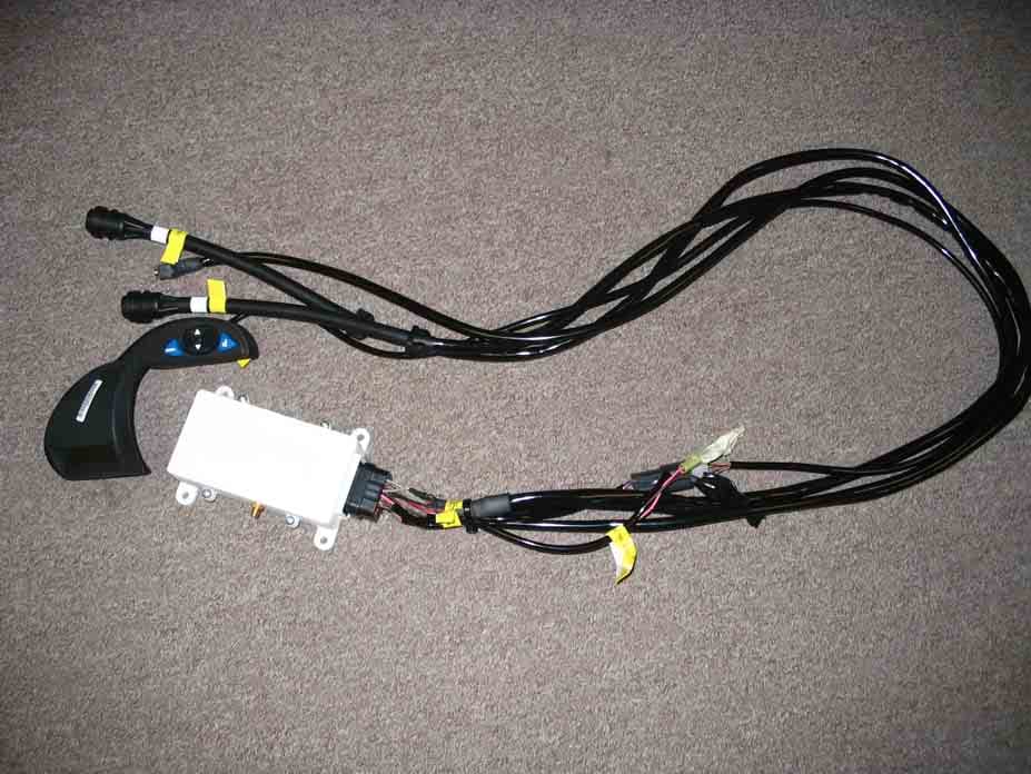
JOFGMSH
Jun 28, 2005N-TOUCH GMRS Communication System
Equipment Class
FRB - Part 95 Family Radio Base Transmitter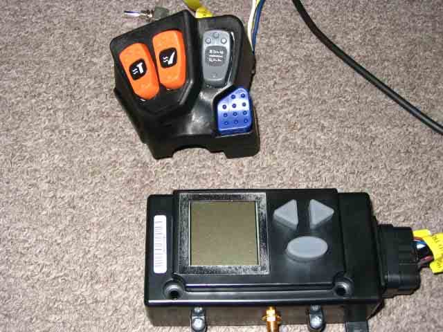
JOFGMOR
Jun 28, 2005Arctic Cat N-Touch Communication System
Equipment Class
FRB - Part 95 Family Radio Base Transmitter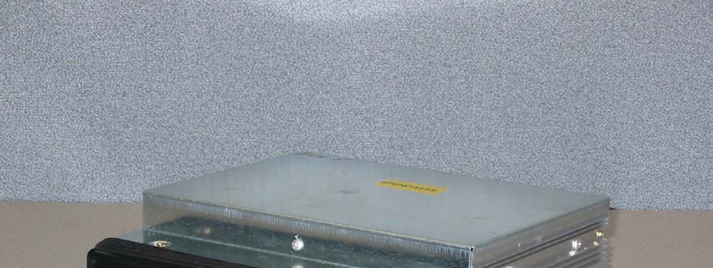
JOFRS9803UDA
Feb 02, 2004Integrated Motorcycle 40 Channel AM CB Transceiver
Equipment Class
TNB - Licensed Non-Broadcast Station Transmitter