JRR24TA-90IRMiniLink 2.4TA-90IR Video Transmitter
Microtek Electronics Inc
Click to zoom
Application Details
- Equipment Class
- TNB - Licensed Non-Broadcast Station Transmitter
- Date of Grant
- Mar 27, 2000
- Application Purpose
- Original Equipment
- Date of Application
- Feb 27, 2000
- Equipment Note
- MiniLink 2.4TA-90IR Video Transmitter
- Frequency Range
- 2458.00000000 - 2474.00000000
- Company
- Microtek Electronics Inc
- Country
- United States
Documents & Files
Document Text
Text extracted from the exhibit documents filed with the FCC. Open a document above to read the original.
Users Manual
Operation The Minilink video transmitter is designed to be used in conjunction with acompatible receiver. Refer to the instructions accompanying your r eceiver for proper installation of that unit.LOCATION:• The Minilink has been designed to be mounted against a flat surface forsupport and stability. ( Note: The location selected for mounting the Minilink should be protected form immersion in water unless the Minilink is enclosedin a watertight enclosure, and should have a moderate shock protection.) POWER:• The Minilink is powered by a 8.5-13.8VDC power supply connected throughthe 4-pin connector harness protruding from the side of the Minilink case. Pin 1) Video In.Pin 2) Video GroundPin 3) Power GroundPin 4) Power Positive SETUP & OPERATION:• Connect Power and video. • Select Frequency MAINTENANCE Your Microtek Electronics product is an example of superior design andcraftsmanship. The following suggestions will help you care for the systems sothat you can enjoy it for years.• Keep the product dry. If it does get wet, wipe it dry immediately. Liquidsmight contain minerals than can corrode the electronic circuits. • Use and store the system only in normal room temperature environments.High temperatures can shorten the life of electronic devices, damagebatteries, and distort or melt plastic parts. • Handle the system gently and carefully. Dropping it can damage the circuitboard and case. Moving or tampering with the system’s internal components can cause amalfunction and invalidate the system’s warranty and void your FCCauthorization to operate it. If your system is not performing, as it should, contactyour dealer. They can assist you and arrange for service, if needed. SPECIFICATIONS 2.4TA-90IR* Dime nsio ns: 2.25”x1.5”x .43” Weight: 1.7 oz. Power Requirements: 8.5-13.8 VDC @ 300 mA Operating Temperature: -10 ° F to 180 ° F Case Temperature Power Output: +24.5dBm (300mW) +1 dBm - 2 dBm Tol. Connections: External Power Supply, Video, Frequency Select Transmitting Frequency: 2458 MHz, 2474 MHz; Deviation ± 4MHz Video Input: 1Volt P-P @75 Ohms Pre-emphasis CCIR 405-1 FCC ID: JRR2.4TA-90IR* Specifications subject to change without notice.
Users Manual
Microtek Electronics, Inc. P.O. Box 3464, San Clemente, CA 92674 Information Hotline 888-36-MICRO Jan 2000 M INI L INK 2.4TA-90IR Video TransmitterThe Minilink transmitter system allows transmissions of wireless signals from aremote location to a monitor or a VCR.The system uses advanced micro circuitry for a compact miniature design, allpackaged within a rugged metal case.The Minilink transmitter’s output frequency is user selectable to one of twofrequencies on the 2400-MHz band. FCC NOTICE This equipment has been tested and found to comply with the limits of a Class B device,pursuant to PART 90 of the FCC Rules. These limits are designed to provide reasonableprotection against harmful interference.This equip me nt ge nerates, uses a nd ca n radiate radio frequenc y e nergy, a nd, i f notinstalled and used in accordance with the instructions, may cause harmful interference toradio communications. However, there is no guarantee that interference will not occur ina particular installation. If this equipment does cause harmful interference to radio ortelevision reception, which can be determined by turning the equipment off and on, theuser is encouraged to try to correct the interference by one or more of the followingmeasures:• Reorient or relocate the receiving antenna. • Increase the separation between the equipment and receiver. • Connec t the eq uip me nt into an o utlet o n a circuit different fro m tha t to w hich thereceiver is connected. • Consult your dealer or an experienced radio/TV technician for help. Any changes or modifications not expressly approved by the manufacturer could void theuser’s authority to operate the equipment. M ICROTEK L IMITED W ARRANTY Microtek Electronics extends the follo wing LIMITED WARR ANT Y to theoriginal owner/purchaser of this product:1) If, within one year after date of initial sale, this product, or any part orportion thereof, shall prove upon examination by MICROTEK, to bedefective in material or workmanship, MICROTEK will repair or rep lacesuch part or portion at MICROTEK’s option. The warranty period on therepaired or replaced part or portion of this product shall be limited to theunexpired term of the original warranty. The buyer shall be responsiblefor all shipping and transportation of the product to MICROTEK for anyperformance under this warranty. 2) C o nd it io ns and Exc ep t io ns :a) Any accident to this product, any misuse or abuse, alternation, use inmodified form, or any attempt to repair this product shall void thiswarranty. These conditions to the warranty inc lude, but are notlimited to, incorrect power connections, physical damage due tomechanical shock, exposure to moisture, and circuit modification. b) SHOULD THIS PRODUCT PROVE DEFECTIVE FOLLOWINGPURCHASE, THE BUYER, NOT THE MANUFACTURER,DISTRIBUTOR, OR RETAILER, ASSUMES THE ENTIRE COSTOF ALL SERVICING OR REPAIR, EXCEPT AS OTHERWISEPROVIDED BY THE TERMS OF THIS WARRANTY. c) FOR BREACH OF ANY WRITTEN OR IMPLIED WARRANTYON THIS PRODUCT, THE BUYER IS LIMITED TO THEFOLLOWING DAMAGES. (1) THE COST OF LABOR TOREPAIR OR REPLACE DEFECTIVE PARTS OR PORTIONS OFTHIS PRODUCT, AND (2) THE COST OF THE REPAIRED ORREPLACE PARTS OR PORTIONS OF THIS PRODUCT. d) NO OTHER EXPRESSED OR IMPLIED WARRANTIES HAVEBEEN MADE OR WILL BE MADE ON BEHALF OF MICROTEKWITH RESPECT TO THE SALE, REPAIR, INSTALLATION,OPERATION, OR REPLACEMENT OR THIS PRODUCT.MICROTEK DISCLAIM ANY IMPLIED WARRANTY OFMERCHANTABILITY OF THIS PRODUCT OR ITS FITNESSFOR ANY PURPOSE, AND THE BUYER AGREES THAT THISPRODUCT IS SOLD “AS IS” AND THAT THE ENTIR E RISK OFQUALITY AND PERFORMANC E OF THIS PRODUCT IS WITHTHE BUYER, EXCEPT AS OTHERWISE PROVIDED BY THETERMS OF THIS WARRANTY. e) S o me s tates / ju r is d ic t io ns d o no t allo w e xc lus io ns o r lim it at io ns o fincidental or consequential damages, or limitations on how long animp lied warranty lasts, so the above exc lus ions or limitations may notapply to you. 3) Contact your dealer regarding return authorization for out of warrantyrepairs and any further product information.
Operational Description
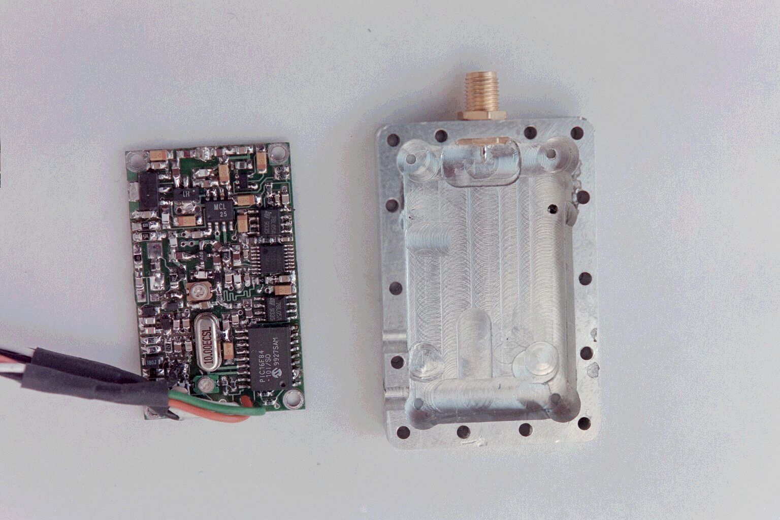
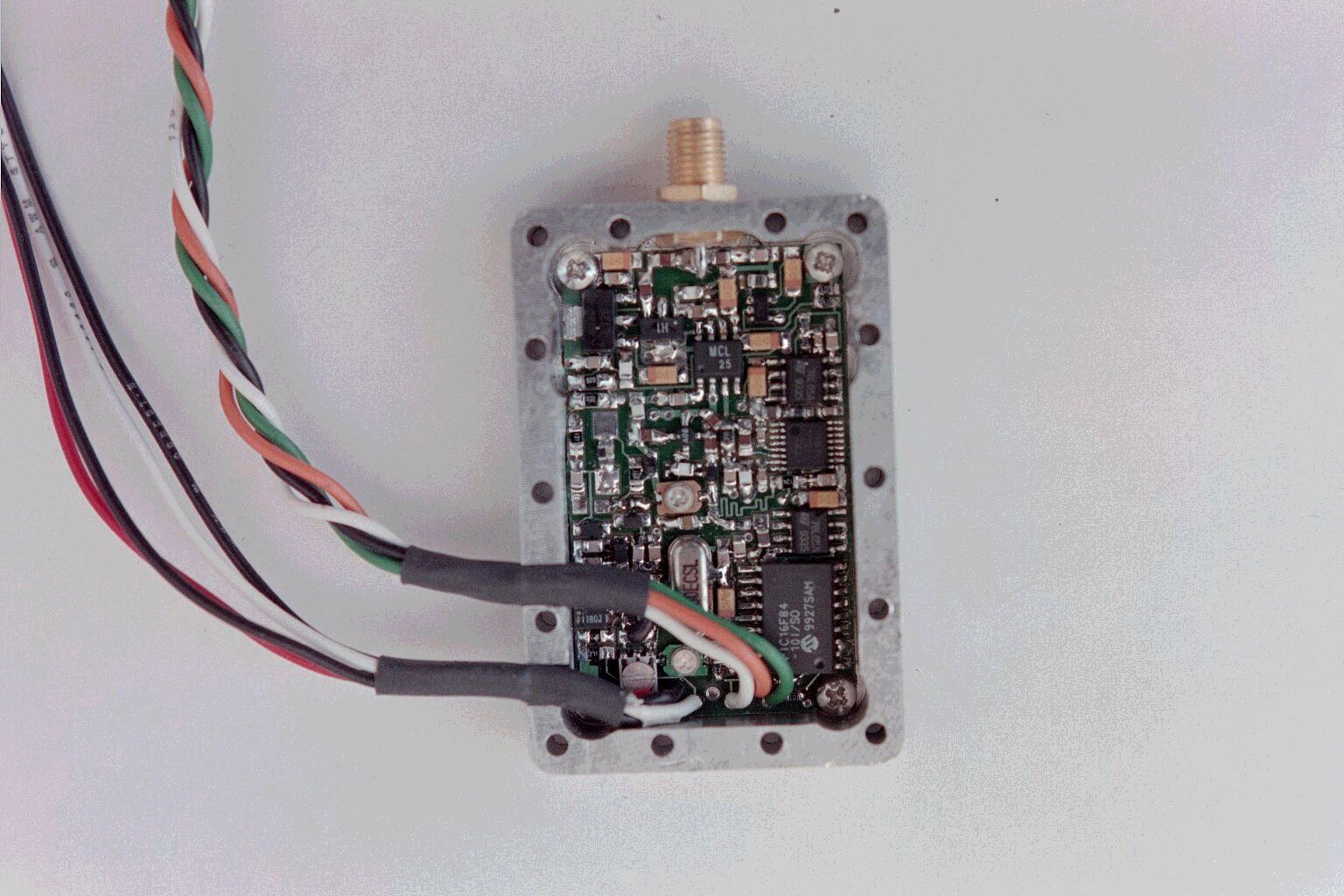
Description of EUT The EUT is a transmitter that allows transmission of Video signals to a remote receiver for viewing. The unit accepts a standard NTSC video input of 1 volt P-P for its modulation input. The unit employs FM modulation (Emission Type 16MOF3F) at either of two user selectable frequencies. Frequencies: 2458 mHz and 2474 mHz. Emission type: 16MOF3F Power Supply: 8.5 – 13.8 Vdc @ <350 Ma. RF Suppression Features: Output Low Pass Filter. Circuit Description The EUT consists of a PLL VCO driving a buffer amplifier and output stage, capable of a maximum power output of +24.5 dBm. The power output is limited by the RF output stage gain and by the previous oscillator stage power saturation level. The RF output passes through a Low Pass filter to reduce spurious output. Frequency stability is achieved by a 50ppm 4 mHz Quart Crystal serving as the PLL reference oscillator. The Voltage Controlled Oscillator (VCO) is divided in frequency and compared to the reference oscillator, an error voltage is produced by the PLL and used to correct the VCO to the proper frequency. The video input passes through a deviation control used to set the proper bandwidth and then through a video Low Pass filter to insure the high frequency noise will not cause over deviation or out of bandwidth operation.
Contact Information
Applicant
Michael L. Henkoski(VP, Engineering)
Test Firm
Compatible ElectronicsScott McCutchan
714-579-0500Fax: 714-579-1850
Technical Specifications
| # | Rule Parts | Frequency Range | Power Output | Emission | Tolerance |
|---|---|---|---|---|---|
| 1 | 90 | 2.46 GHz - 2.47 GHz | 350.00 mW | 16MOF3F | 0.0050000000 % |
Other Applications from Microtek Electronics Inc

JRR24TA-900TIC
Feb 26, 2007Video Transmitter
Equipment Class
TNB - Licensed Non-Broadcast Station Transmitter
JRRWES
Jun 14, 2005MiniLink Wireless Ethernet System
Equipment Class
DTS - Digital Transmission System
JRR-PHIL2-11
Mar 02, 2003Video Transmitter
Equipment Class
TNB - Licensed Non-Broadcast Station Transmitter
JRR-1JOHN4-14
Feb 23, 2003Video Transmitter
Equipment Class
TNB - Licensed Non-Broadcast Station Transmitter
JRR-PHL4-13
Nov 11, 2002Video/Audio Transmitter Module
Equipment Class
DXX - Part 15 Low Power Communication Device Transmitter