K5B-CANBRIDGECANbridge Controller
Matric Limited
Click to zoom
Application Details
- Equipment Class
- DSS - Part 15 Spread Spectrum Transmitter
- Date of Grant
- Apr 29, 2001
- Application Purpose
- Original Equipment
- Date of Application
- Jan 05, 2001
- Equipment Note
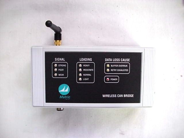
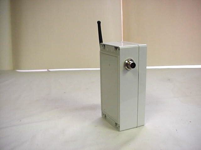
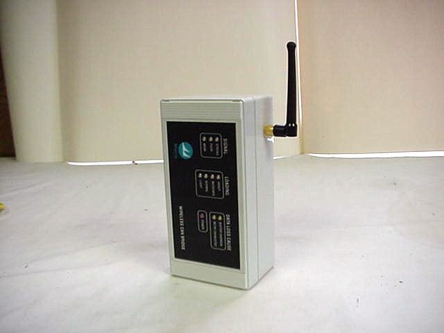
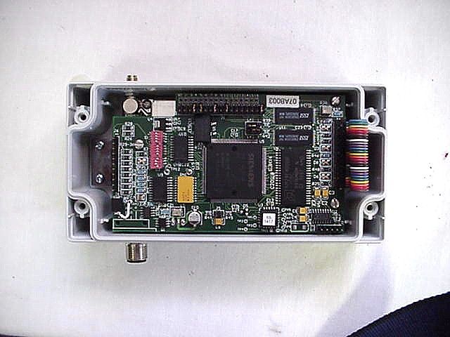
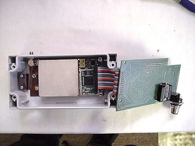
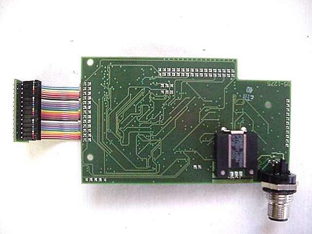
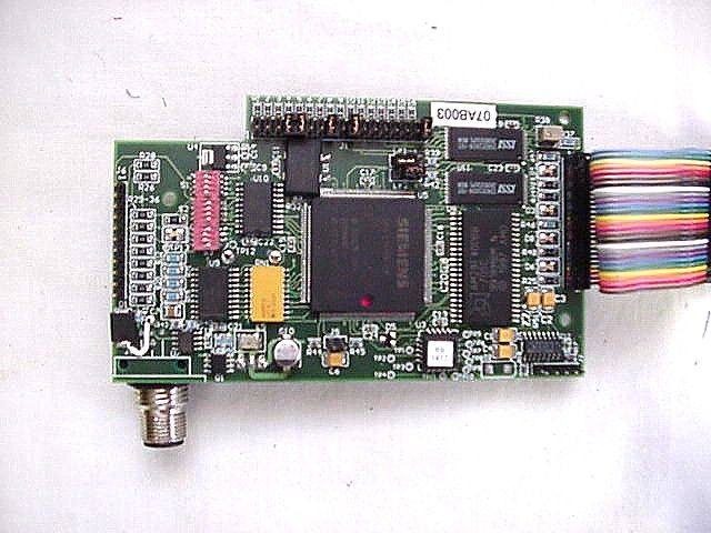
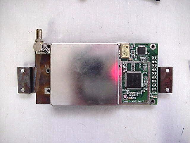
- CANbridge Controller
- Frequency Range
- 2410.50000000 - 2410.50000000
- Company
- Matric Limited
- Country
- United States
Documents & Files
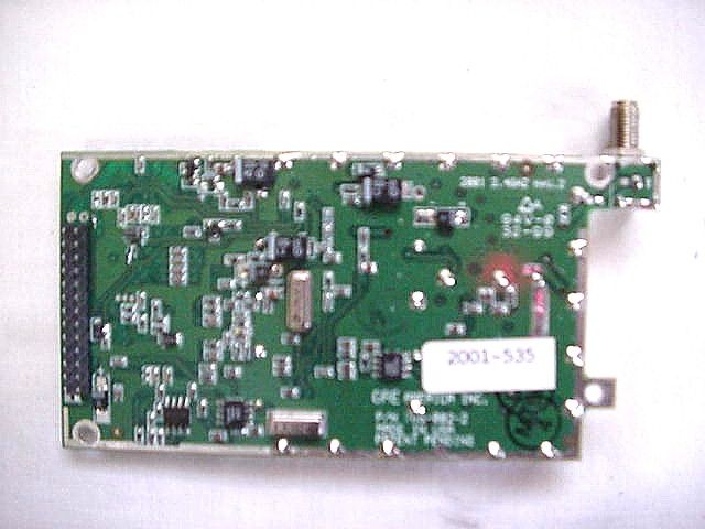
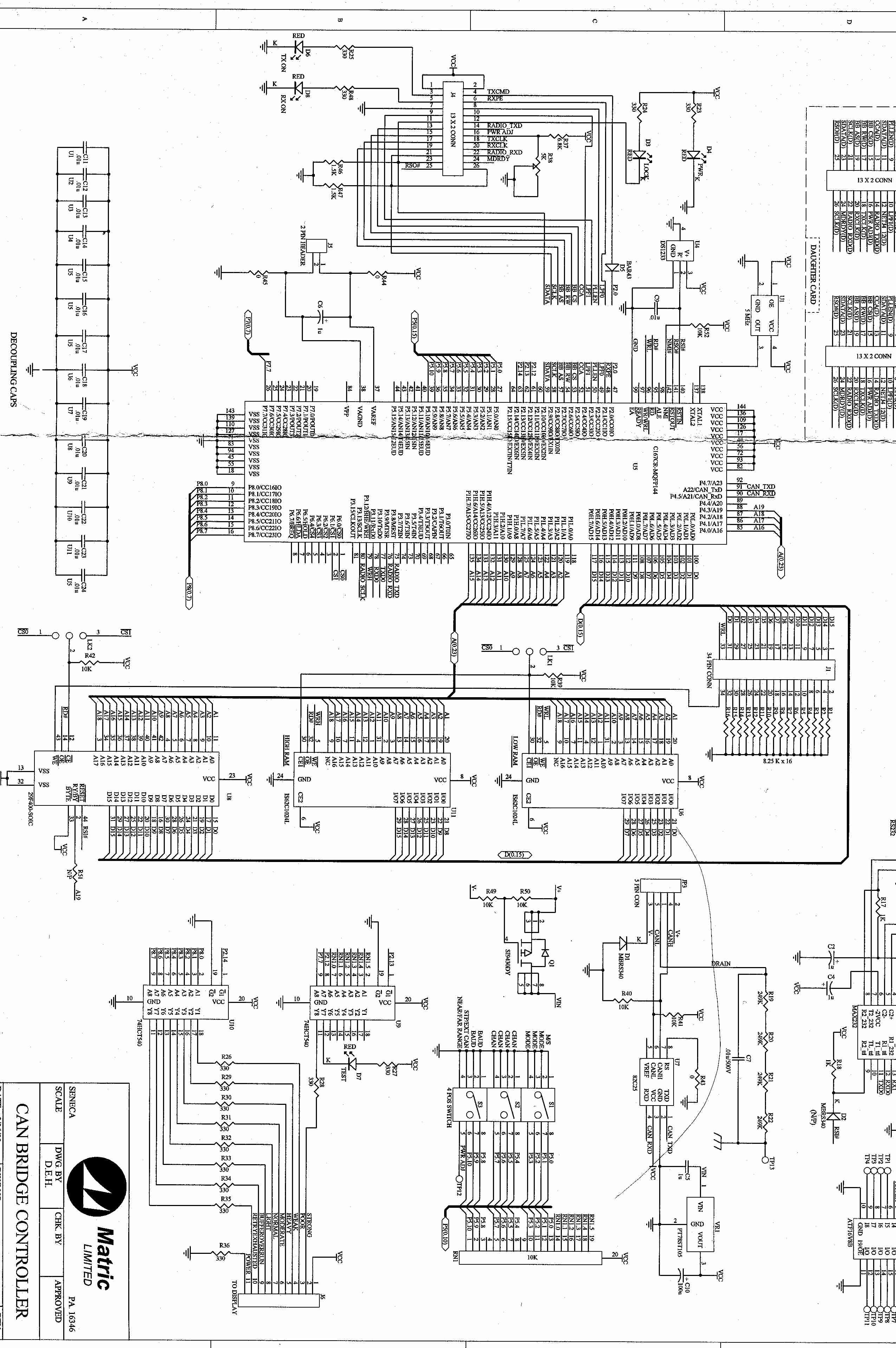
Document Text
Text extracted from the exhibit documents filed with the FCC. Open a document above to read the original.
ID Label/Location Info
FCC ID LABEL FORMAT AND LOCATION BOTTOM VIEW SERIAL NO. XXXXXXXXXXX FCCID: K5B-CANBRIDGE This device complies with Part 15 of the FCC Rules. Operation of this device is subject to the following conditions: (1) This device may not cause harmful interference, and (2) this device must accept any interference received, including interference which may cause undesired operation. MADE IN USA
Test Report
N N N a a a t t t i i i o o o n n n a a a l l l C C C e e e r r r t t t i i i f f f i i i c c c a a a t t t i i i o o o n n n L L L a a a b b b o o o r r r a a a t t t o o o r r r y y y 8370 Court Avenue, Suite B-1 Ellicott City, Maryland 21043 (410) 461-5548 FOR Matric Ltd. Hill City Road R.R. #1, Box 421A Seneca, PA 16346 FCC ID: K5B-CANBRIDGE December 8, 2000 FCC REPORT OF RADIO INTERFERENCE FCC ID #: K5B-CANBRIDGE 1 TABLE OF CONTENTS 1.0Introduction 1.1Summary 2.0Description of Equipment Under Test (EUT) 2.1EMI Countermeasure 3.0Test Program 4.0 Test Configuration 5.0Conducted Emissions Scheme 6.0Radiated Emissions Scheme TABLES Table 1.Support Equipment Table 2.Interface Cables Table 3.Measurement Equipment EXHIBITS Exhibit 1.EUT Photographs Exhibit 2.Schematic Diagram Exhibit 3.User Manual NCL PROJ.# MATRIC-563 FCC ID #: K5B-CANBRIDGE 2 1.0 Introduction: This report has been prepared on behalf of Matric Limited, to support the attached Application for a Certification of a Part 15 Spread Spectrum Transmitter module. The Equipment Under Test (EUT) was the Model: Wireless CAN BridgeTransceiver. Radio-Noise Emissions tests were performed according to FCC Public Notice 54797, titled “Guidance on Measurement for Direct Sequence SST”. The measuring equipment conforms to ANSI C63.2 Specifications for Electromagnetic Noise and Field Strength Instrumentation. Testing was performed at National Certification Laboratory in Ellicott City, MD. Site description and site attenuation data have been placed on file with the FCC’s sampling and Measurements Branch. FCC acceptance was granted on May 26, 1993. 1.1 Summary: The Matric Limited Wireless CAN BridgeTransceiver complies with the FCC limits (15.247) for a Direct Sequence SST. FCC ID #: K5B-CANBRIDGE 3 2.0 Description of Equipment Under Test (EUT): The EUT features: 3.0 Test Program: This report contains measurement charts and data as evidence for the following tests performed: 1.(15.247b) Peak RF output power. 2. (15.247c) Field Strength of harmonics and spurious out-of-band emissions. 3. (15.247c) RF Antenna Conducted of harmonics and spurious out-of-band emissions. 4. (15.247a) 6 dB Emission Bandwidth. 5. (15.207) Power Line Conducted Emissions. 6.(15.247d) Power Spectral Density. Reverse Polarity SMA Antenna Connector per 15.203 +10 dBm Max. RF Output 2410.50 MHz Center Frequency 13.2 MHz 6 dB Emission Bandwidth Single Channel 1 Mbps Max. Data Rate (DBPSK) 4 inch Monopole External Antenna (2.5 dBi) FCC ID #: K5B-CANBRIDGE 4 4.0 Test Configuration: RF antenna output tests such as Bandwidth, Spurious/Harmonics, Power output, were taken with the transmitter antenna connector feeding directly into the spectrum analyzer via external 30 db attenuator, or into the Peak RF Power meter as appropriate. The analyzer’s internal attenuator was adjusted to prevent overloading of the front end. The transmitter is modulated at 1 Mbps which is the highest available data rate. Field strength measurements were taken with the transmitter feeding a 2.5 dBi monopole omni antenna aligned with the measurement horn antenna. No other antennas are provided with the EUT. Testing was performed at maximum RF power output. PEAK POWER TEST RESULTS Limit:1 watt (30 dBm) Condition:Transmitter is set to a single modulated channel at full RF power. Reading from Peak RF Power meter: Channel :2410.50 MHz-(+9.9 dBm) FCC ID #: K5B-CANBRIDGE 5 6 dB EMISSION BANDWIDTH Minimum 6 dB BW:500 kHz RBW Setting on S.A.:100 kHz Condition:Transmitter is set to a single channel modulated at 1 Mbps at full RF power Reading from Spectrum Analyzer: Channel :2410.50 MHz- (13.2 MHz) 6 dB EMISSION BANDWIDTH – (100 kHz RES. BW) FCC ID #: K5B-CANBRIDGE 6 POWER SPECTRAL DENSITY Limit: 8 dBm Resolution Bandwidth: 3 kHz Average Time Interval: 1 second/3 kHz Actual Time Interval used for testing: 1.5 seconds/3 kHz Condition:Transmitter is set to a single channel modulated at 1 Mbps at full RF power. Note: 30 dB front-end attenuator on analyzer Reading from spectrum analyzer: Channel: 2410.50 MHz - -2.2 dBm FCC ID #: K5B-CANBRIDGE 7 RF ANTENNA CONDUCTED SPURIOUS/HARMONICS EMISSIONS Limit below Fc level: 20 dB below Carrier Level Measured with 100 kHz RBW RBW Setting on S.A.: 100 kHz Condition:Transmitter is set to a single modulated channel at full RF power. FCC Part 15.247(c) – Conducted Spurious Emissions Frequency of Carrier = 2410.50 MHz Limit = 20 dBc TEST RESULTS ComponentFrequency (MHz)Result (dB Below Peak) Harmonic4821.00-57.0 Harmonic7231.50-59.0 Harmonic9642.00-64.0 Harmonic12052.50-69.0 Harmonic14463.00-71.0 Harmonic16873.50-74.0 Harmonic19284.00-75.0 Harmonic21694.50-75.0 Harmonic24105.00-75.0 FCC ID #: K5B-CANBRIDGE 8 5.0 Test Configuration for Conducted and Radiated Emissions: The EUT was set up on the center of the test table, in a manner which follows the general guidelines of ANSI C63.4, Section 6 “General Operating Conditions and Configurations”. A 4 inch monopole antenna is attached to the transmitter via reverse polarity SMA connector. The transmitter is turned on and automatically begins transmission at full RF power output, once initialized. 6.0 Conducted Emissions Scheme: The EUT is placed on an 80 cm high X 1.5 m non-conductive table. Power to the RF modem is provided through a Solar Corporation 50 ohm/50 uH Line Impedance Stabilization Network bonded to a 2.2 X 2 meter horizontal ground plane, and a 2.2 X 2 meter vertical ground plane. The LISN has its AC input supplied from a filtered AC power source. A separate LISN provides AC power to the peripheral equipment. I/O cables are moved about to obtain maximum emissions. The 50 ohm output of the LISN is connected to the input of the spectrum analyzer and emissions in the frequency range of 450 kHz to 30 MHz are searched. The detector function is set to Quasi-Peak and the resolution bandwidth is set at 9 kHz, with all post detector filtering no less than 10 times the resolution bandwidth for final measurements. All emissions within 20…
Text truncated - open the document above for the full version.
Contact Information
Applicant
Don Frazier(Manufacturing Engineering Manager)
Technical Contact
National Certification LabBrian Haghtalab
[email protected]410 461 5548
R.R. #1 Box 421A · Ellicott City, Pennsylvania · United States
Non-Technical Contact
Matric Ltd.Stephen R Scheer
[email protected]814 677 0716
Test Firm
National Certification LaboratoryBrian Haghtalab
Technical Specifications
| # | Rule Parts | Frequency Range | Power Output |
|---|---|---|---|
| 1 | 15C | 2.41 GHz - 2.41 GHz | 10.00 mW |
Other Applications from Matric Limited
K5B-CB500LR
Oct 16, 2006Wireless CAN Bridge 500
Equipment Class
DTS - Digital Transmission System
K5B-CB500
Nov 08, 2005Wireless CAN Bridge
Equipment Class
DTS - Digital Transmission System
K5B-TP105
Jun 27, 2001Industrial Remote Control
Equipment Class
DXX - Part 15 Low Power Communication Device Transmitter
K5B-TP100
Apr 16, 2001Low Power Process Control Transmitter
Equipment Class
DXX - Part 15 Low Power Communication Device TransmitterK5B03U2050942
Apr 21, 1996Keyboard
Equipment Class
JBP - Part 15 Class B Computing Device Peripheral