K5B-CB500LRWireless CAN Bridge 500
Matric Limited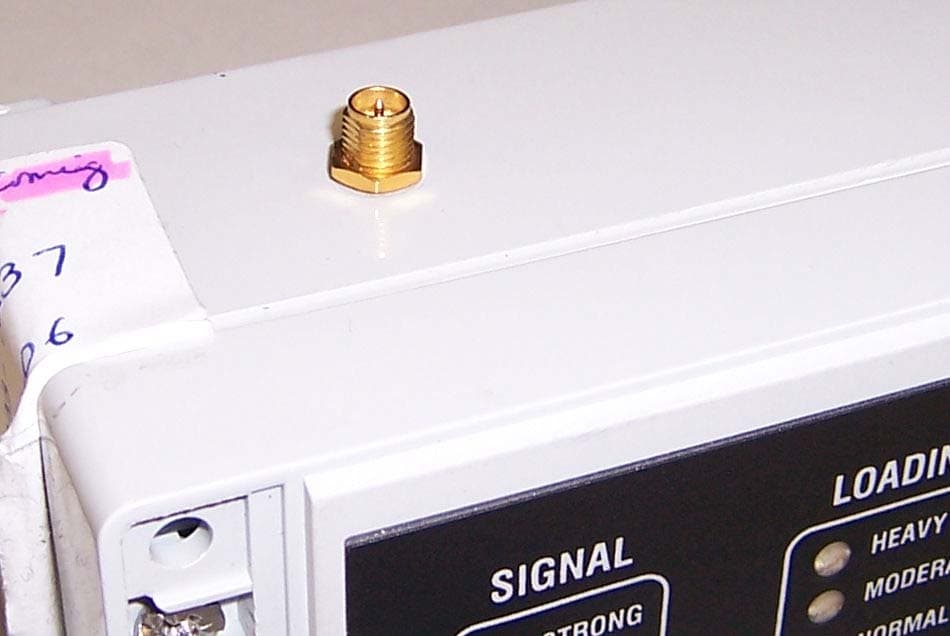
Click to zoom
Application Details
- Equipment Class
- DTS - Digital Transmission System
- Date of Grant
- Oct 16, 2006
- Application Purpose
- Original Equipment
- Date of Application
- Oct 16, 2006
- Equipment Note
- Wireless CAN Bridge 500
- Frequency Range
- 2405.00000000 - 2475.00000000
- Company
- Matric Limited
- Country
- United States
Documents & Files
Document Text
Text extracted from the exhibit documents filed with the FCC. Open a document above to read the original.
Users Manual
Technical Manual Wireless CAN Bridge 500 (CB-500LR) Matric Technical Manual 185-0054, V1 Page 1 of 12 DESCRIPTION: The Wireless CAN Bridge functions as a wireless link that transfers CAN messages. Using the Wireless CAN Bridge, nodes on either side of a wireless link can communicate at a separation of up to 1400 feet. A full 64 node DeviceNet* can be implemented depending on scan rates and frame density. Since actual CAN messages are transferred, the Wireless CAN Bridge supports any type of CAN bus standard including CAN Open and CAN Kingdom. CAN BRIDGE SCANNER NODE MOTOR CONTROL NODE SENSOR NODE Virtual Trunk Line TerminatorTap Trunk Line Trunk Line (extended by CAN Bridge) I/O BLOCK NODE CAN BRIDGE Technical Manual Wireless CAN Bridge 500 (CB-500LR) Matric Technical Manual 185-0054, V1 Page 2 of 12 SPECIFICATIONS: Functional 1200 frames per second transfer rate (max) Supports any CAN Bus or DeviceNet* (Bosch CAN 2.0b) Network baud rate (125K, 250K, 500K) Five pin male micro connector 16 bit CPU CPU watchdog Radio Typical range of 1400 feet with unobstructed line of sight 2.4 – 2.4835 GHz with 15 channels FSK modulation Output power, 3.5 mW Single heterodyne conversion Radio complies with FCC Part 15B, no user license required Configuration Options Configuration via internal dip switches Radio link master or slave Standard versus extended CAN frame formats Frequency agile enable / disable Channel (1-15) Radio retry level Power Source Requires SELV power supply at connector “Network”. See installation section for wiring information. 7-30VDC, 200 mA at 24VDC +/- 5% Status Indicators Signal strength Bus loading Data Loss Cause Power Physical Size: 3 1/8 X 3 X 6 5/16 Inches Weight: 1 Lb DIN rail or panel mount Sealed enclosure Operational temperature 0°C to 70°C Storage temperature -40ºC to 85ºC Technical Manual Wireless CAN Bridge 500 (CB-500LR) Matric Technical Manual 185-0054, V1 Page 3 of 12 APPLICATION: The Wireless CAN Bridge provides a frame transfer rate of 1200 CAN frames per second which is roughly equivalent to a fully loaded 125k baud system. The effectiveness of the CAN Bridge in any particular application depends on network loading. The loading on a CAN based network is affected by a number of factors including: polling rate of the network scanner, node count, change-of-state activity, and device power up behavior. According to ODVA, 30% loading is recommended for DeviceNet systems employing change-of-state devices and 80% loading is recommended for polled DeviceNet systems. Heavily loaded systems increase the probability that CAN messages will be discarded due to RF bandwidth limitations. The transfer rate of 1200 fps is based on a typical scenario of less than 1400 feet separation without significant RF obstacles. The actual transfer rate in any application is dependent upon the quality of the RF link. Structural components such as steel walls or decking, earth tunnels, and metal equipment can affect the quality of the RF link. Also, radiation sources such as other radio systems, high power switching, and magnetic fields can affect the quality of the RF link. A site assessment should be performed at any site where a new RF control is to be installed. The Wireless CAN Bridge provides a point-to-point data transfer in order to achieve the required throughput over the wireless link. A system requiring multiple wireless links can accomplish this using multiple pairs of the Wireless CAN Bridge set to different channels. The rate at which CAN frames are received and transmitted by the Wireless CAN Bridge falls within the timing constraints of Bosch CAN Standard 2.0b. While meeting network requirements for data link and higher levels of communication, the time required for retransmission may still have an effect on the overall timing of a control system. Technical Manual Wireless CAN Bridge 500 (CB-500LR) Matric Technical Manual 185-0054, V1 Page 4 of 12 S1 1 2 3 4 RADIO BOARD LED CONNECTOR 6 5 S2 OFF ON 1 2 3 4 6 5 OFF ON CONFIGURATION: Configuration of the Wireless CAN Bridge is accomplished by manually setting switches inside its enclosure. The CAN Bridge enclosure lid must be removed to access the configuration switches. Users may only perform the configuration described in this manual. Changing other switch or trimmer settings may invalidate agency approvals. To access configuration switches, first, use a flat screwdriver to pry off the two decorative covers at the right and left ends of the lid. Four pry slots are provided as shown below. Then unscrew the four screws that attach the lid to the chassis of the Wireless CAN Bridge using a philips or a flat screwdriver. The Wireless CAN Bridge has 12 configuration switches arranged in 2 banks S1 and S2. Each bank contains 6 switches. These switches allow the user to easily customize the Wireless CAN Bridge to fit the desired application. POWER BUFFER OVERRUN RETRY EXHAUSTED HEAVY MODERATE NORMAL LIGHT LOADINGDATA LOSS CAUSE STRONG POOR WEAK SIGNAL WIRELESS CAN BRIDGE Technical Manual Wireless CAN Bridge 500 (CB-500LR) Matric Technical Manual 185-0054, V1 Page 5 of 12 IMPORTANT: Employ ESD precautions to avoid static discharge when touching the CAN Bridge circuit board. ESD can cause damage leading to catastrophic or intermittent product failure modes. The following paragraphs describe each switch setting in more detail. The format Sb:s, where b is the bank number and s is the switch number within that bank, will be used. The “as shipped” settings are shown with an asterisk “*”. The CB-500LR must be reset (power cycled) before switch settings take effect. Switch S1:1 Selects Node Communication Type for internal radios. A Radio System must consist of only one Server (master) and only one Client (slave) per channel. The Server is the initiator of the radio pair. Before the radios link, the Client will only listen for a Server and the Server will transmit to find a Client. Radio Operation S1:1 Server ON Client OFF* Switch S1:2 Reserv…
Text truncated - open the document above for the full version.
Cover Letter(s)
Response to ATCB Comments FCC ID: KB5-CB500LR 1 Washington Laboratories, Ltd. 7560 LINDBERGH DRIVE GAITHERSBURG, MD 20879 (301) 417 – 0220 FAX # (301) 417 - 9069 October 12, 2006 Mr. Timothy Johnson American Telecommunications Certification Body Inc. 6731 Whittier Ave McLean, VA 22101 RE: Comments of September 26, 2006 APPLICATION: KB5-CB500LR Matric Limited Dear Mr. Johnson: Below are the comments that you have provided regarding the application for certification referenced above. Our responses to those comments are in bold italic. Many responses refer you to additional exhibit(s) which has been uploaded to the application folder at the ATCB website. Thank you for your attention. Please feel free to contact us for any additional information that you may require. Regards, Gregory M. Snyder Chief EMC Engineer, Wireless/Telco Services Manager Brian J. Dettling Documentation Specialist WLL Project: 9233 1) According to recent FCC interpretations, the confidentiality letter must be signed by either the contact given on the FCC site for the applicant, or someone listed in the technical or non-technical portions of the 731 form. Rick Rogers does not appear to be listed on the FCC site as the appropriate contact (FCC site shows Don Frazier). Please help correct the cover letters as necessary. R. A new letter has been provided. Please see “CB500LR Cover Letter - RFC revised”. 2) It is unsure if the device is in compliance to 15.203. Please explain. R. The unit has a reverse SMA connector. Please see “Antenna Connector Photo”. 3) Test photographs appear to show a Whip, MaxRad and PC2415 Antenna. MaxRad appears to be an omnidirectional, but various exhibits mention a yagi antenna. If either one of these is the yagi antenna, it Response to ATCB Comments FCC ID: KB5-CB500LR 2 was not positioned such that maximum lobe of radiation was horizontal. Additionally the test report appear to label the 5 dBi a MaxRad antenna while the photos suggest otherwise. R. The Yagi antenna is a Cushcraft Model PC2415 antenna. The error was discovered and the test was repeated with the antenna correctly positioned. Please see “CB500LR Test Setup Photos – Addendum”. The other two antennas are MaxRad OMNI antennas. One is a MaxRad 5dBi Model MAXC245005 and the other one is a MaxRad MFB24010 (actually a collinear array). 4) Gain of antennas listed in the MPE exhibit exceed maximum gain as given in the users manual. Please review/correct. R. The Users Manual has been updated to the 16dBi maximum gain antenna as was tested with the unit. Please see “Manual, CB-500 Long Range, V1”. Industry Canada: 5) Has information regarding receiver emissions (radiated/conducted) been provided? R. Yes, the emissions data for the receiver have been reported along with the transmitter emissions.
Cover Letter(s)
Response to ATCB Comments FCC ID: KB5-CB500LR 1 Washington Laboratories, Ltd. 7560 LINDBERGH DRIVE GAITHERSBURG, MD 20879 (301) 417 – 0220 FAX # (301) 417 - 9069 October 17, 2006 Mr. Timothy Johnson American Telecommunications Certification Body Inc. 6731 Whittier Ave McLean, VA 22101 RE: Comments of October 17, 2006 APPLICATION: KB5-CB500LR Matric Limited Dear Mr. Johnson: Below are the comments that you have provided regarding the application for certification referenced above. Our responses to those comments are in bold italic. Many responses refer you to additional exhibit(s) which has been uploaded to the application folder at the ATCB website. Thank you for your attention. Please feel free to contact us for any additional information that you may require. Regards, Gregory M. Snyder Chief EMC Engineer, Wireless/Telco Services Manager Brian J. Dettling Documentation Specialist WLL Project: 9233 1) The response mentions the Yagi was retested. However it does not appear a new test report has been provided. It would be expected some results, especially bandedge, may change. Please explain. R. The response is referring to the original testing. The "retesting" of the Yagi antenna in the correct position was performed at the time the incorrect antenna positioning was discovered. No new data was obtained for the response.
External Photos
External Photos ©2006 Washington Laboratories, Ltd External Photos ©2006 Washington Laboratories, Ltd External Photos ©2006 Washington Laboratories, Ltd
ID Label/Location Info
Label & Location ©2006 Washington Laboratories, Ltd Matric Limited MODEL: CB500LR S/N: FCC ID: K5B-CB500LR IC: 3926A-CB500LR This device complies with Part 15 of the FCC Rules. Operation of this device is subject to the following conditions: (1) This device may not cause harmful interference, and (2) this device must accept any interference received, including interference which may cause undesired operation. MADE IN USA
Internal Photos
Internal Photos ©2006 Washington Laboratories, Ltd Internal Photos ©2006 Washington Laboratories, Ltd Internal Photos ©2006 Washington Laboratories, Ltd Internal Photos ©2006 Washington Laboratories, Ltd Internal Photos ©2006 Washington Laboratories, Ltd
RF Exposure Info
Document 9233-MPE FCC ID: K5B-CB500LR IC: 3926A-CB500LR RF Exposure Test Report Washington Laboratories, Ltd September 2006 Maximum Permissible Exposure Evaluation for Matric Limited CAN Bridge CB-500LR FCC ID: K5B-CB500LR IC: 3926A-CB500LR September 5, 2006 WLL PROJECT #: 9233X This report may not be reproduced, except in full, without the prior written consent of Washington Laboratories, Ltd. RF Exposure Evaluation Document 9233-MPE FCC ID: K5B-CB500LR IC: 3926A-CB500LR RF Exposure Test Report Washington Laboratories, Ltd September 2006 1 Maximum Permissible Exposure Evaluation for FCC ID: K5B-CB500LR IC: 3926A-CB500LR 1.0 Introduction This report has been prepared on behalf of Matric Limited Model: CAN Bridge CB-500LR to show compliance with the RF exposure requirements as defined in FCC §1.1307. 1.1 Requirements Three different categories of transmitters are defined by the FCC in OET Bulletin 65. These categories are fixed installation, mobile, and portable and are defined as follows: Fixed Installations: fixed location means that the device, including its antenna, is physically secured at a permanent location and is not able to be easily moved to another location. Additionally, distance to humans from the antenna is maintained to at least 2 meters. Mobile Devices: a mobile device is defined as a transmitting device designed to be used in other than fixed locations and to be generally used in such a way that a separation distance of at least 20 centimeters is normally maintained between the transmitter's radiating structures and the body of the user or nearby persons. Transmitters designed to be used by consumers or workers that can be easily re-located, such as a wireless modem operating in a laptop computer, are considered mobile devices if they meet the 20 centimeter separation requirement. The FCC rules for evaluating mobile devices for RF compliance are found in 47 CFR §2.1091. Portable Devices: a portable device is defined as a transmitting device designed to be used so that the radiating structure(s) of the device is/are within 20 centimeters of the body of the user. Portable device requirements are found in Section 2.1093 of the FCC's Rules (47 CFR§2.1093). For this test report the Matric Limited CAN Bridge CB-500LR will be classified as a “Mobile Device” and the MPE will be evaluated at the 20cm test distance. Document 9233-MPE FCC ID: K5B-CB500LR IC: 3926A-CB500LR RF Exposure Test Report Washington Laboratories, Ltd September 2006 2 The FCC also categorizes the use of the device as based upon the user’s awareness and ability to exercise control over his or her exposure. The two categories defined are Occupational/ Controlled Exposure and General Population/Uncontrolled Exposure. These two categories are defined as follows: Occupational/Controlled Exposure: In general, occupational/controlled exposure limits are applicable to situations in which persons are exposed as a consequence of their employment, who have been made fully aware of the potential for exposure and can exercise control over their exposure. This exposure category is also applicable when the exposure is of a transient nature due to incidental passage through a location where the exposure levels may be higher than the general population/uncontrolled limits, but the exposed person is fully aware of the potential for exposure and can exercise control over his or her exposure by leaving the area or by some other appropriate means. Awareness of the potential for RF exposure in a workplace or similar environment can be provided through specific training as part of a RF safety program. If appropriate, warning signs and labels can also be used to establish such awareness by providing prominent information on the risk of potential exposure and instructions on methods to minimize such exposure risks. General Population/Uncontrolled Exposure: The general population / uncontrolled exposure limits are applicable to situations in which the general public may be exposed or in which persons who are exposed as a consequence of their employment may not be made fully aware of the potential for exposure or cannot exercise control over their exposure. Members of the general public would come under this category when exposure is not employment-related; for example, in the case of a wireless transmitter that exposes persons in its vicinity. Warning labels placed on low-power consumer devices such as cellular telephones are not considered sufficient to allow the device to be considered under the occupational/controlled category, and the general population/uncontrolled exposure limits apply to these devices. Since there are no warnings or training associated with this unit and it can be used by anyone, the Matric Limited CAN Bridge CB-500LR is evaluated to the General Population/Uncontrolled Exposure limits. 1.2 Radio Frequency Radiation Exposure Evaluation The highest RF output power of the unit was measured at 5.5 dBm (3.55mW) at 2475 MHz. According to §1.1310 of the FCC rules, the power density limit for General Population/Uncontrolled Exposure at 2475MHz is 1mW/cm 2 . As this is a mobile device the MPE shall be calculated at 20cm to show compliance with the power density limit. The highest gain antennas being evaluated for this device are: • 1 and 5 dBi whips • 10 dBi collinear array Document 9233-MPE FCC ID: K5B-CB500LR IC: 3926A-CB500LR RF Exposure Test Report Washington Laboratories, Ltd September 2006 3 • 16 dBi Yagi The following formula was used to calculate the minimum safe distance: 2 4R PG S π = Where: S = Power Density P = Output Power at the Antenna Terminals G = Gain of Transmit Antenna (linear gain) R = Distance from Transmitting Antenna For this device, the calculation is as follows: R = 20cm P = Output Power = 3.55 mW G = Worst Case Gain = 16dBi = INVLOG(16/10) = 39.8 Frequency 2475 MHz Limit 1.000 mW/cm^2 Dista nce (cm), R = 20 cm Pow er (dBm), P = 5.5 dBm3.55 mW TX Ant Gain (dB), G = 16 dB Pow er De nsi…
Text truncated - open the document above for the full version.
Test Report
FCC & Industry Canada Certification Test Report For the Matric Limited CAN Bridge CB-500LR FCC ID: K5B-CB500LR IC ID: 3926A-CB500LR WLL JOB# 9233 August 31, 2006 Prepared for: Matric Limited 2099 Hill City Road Seneca, PA 16346 Prepared By: Washington Laboratories, Ltd. 7560 Lindbergh Drive Gaithersburg, Maryland 20879 Matric Limited CAN Bridge CB-500 FCC & IC Certification Test Report August 2006 FCC & Industry Canada Certification Test Report for the Matric Limited CAN Bridge CB-500LR FCC ID: K5B-CB500LR IC ID: 3926A-CB500LR August 31, 2006 WLL JOB# 9233 Prepared by: Brian J. Dettling Documentation Specialist Reviewed by: Gregory M. Snyder Chief EMC Engineer Matric Limited CAN Bridge CB-500 FCC & IC Certification Test Report August 2006 WLL Report #9233-01 - ii - © 2006 Washington Laboratories, Ltd. Abstract This report has been prepared on behalf of Matric Limited to support the attached Application for Equipment Authorization. The test report and application are submitted for a Digital Transmissions System under Part 15.247 of the FCC Rules and Regulations and Spectrum Management and Telecommunications Policy RSS-210 of Industry Canada. This Certification Test Report documents the test configuration and test results for a Matric Limited CAN Bridge CB-500LR. Testing was performed on an Open Area Test Site (OATS) of Washington Laboratories, Ltd, 7560 Lindbergh Drive, Gaithersburg, MD 20879. Site description and site attenuation data have been placed on file with the FCC's Sampling and Measurements Branch at the FCC laboratory in Columbia, MD. The Industry Canada OATS numbers are 3035A-1 and 3035A-2 for Washington Laboratories, Ltd. Site 1 and Site 2, respectively. Washington Laboratories, Ltd. has been accepted by the FCC and approved by NIST NVLAP (NVLAP Lab Code: 200066-0) as an independent FCC test laboratory. The Matric Limited CAN Bridge CB-500LR complies with the limits for a Digital Transmissions System under FCC Part 15.247 and Industry Canada RSS-210. Matric Limited CAN Bridge CB-500 FCC & IC Certification Test Report August 2006 WLL Report #9233-01 - iii - © 2006 Washington Laboratories, Ltd. Table of Contents Abstract ........................................................................................................................................... ii 1 Introduction..........................................................................................................................1 1.1 Compliance Statement .....................................................................................................1 1.2 Test Scope ........................................................................................................................1 1.3 Contract Information........................................................................................................1 1.4 Test Dates ........................................................................................................................1 1.5 Test and Support Personnel .............................................................................................1 2 Equipment Under Test .........................................................................................................2 2.1 EUT Identification & Description ...................................................................................2 2.2 Test Configuration ...........................................................................................................2 2.3 Testing Algorithm............................................................................................................2 2.4 Test Location ...................................................................................................................2 2.5 Measurements ..................................................................................................................3 2.5.1 References....................................................................................................................3 2.6 Measurement Uncertainty................................................................................................3 3 Test Equipment ....................................................................................................................4 4 Test Results ..........................................................................................................................5 4.1 RF Power Output: (FCC Part §2.1046) ...........................................................................5 4.2 Occupied Bandwidth: (FCC Part §2.1049) ......................................................................9 4.3 RF Peak Power Spectral Density (§15.247(e) and RSS-210, Annex 8.2) .....................13 4.4 Conducted Spurious Emissions at Antenna Terminals (FCC Part §15.247(d)) ............17 4.5 Radiated Spurious Emissions: (FCC Part §2.1053).......................................................40 4.5.1 Test Procedure.........................................................................................................40 4.5.2 Test Results...............................................................................................................40 4.6 AC Powerline Conducted Emissions: (FCC Part §15.207 and RSS-GEN)...................45 List of Tables Table 1. Device Summary............................................................................................................... 2 Table 2: Test Equipment List.......................................................................................................... 4 Table 3. RF Power Output .............................................................................................................. 5 Table 4. Occupied Bandwidth Results.......................................................................................... 13 Table 5. RF Power Spectral Density.............................................................................................16 Table 6: Radi…
Text truncated - open the document above for the full version.
Test Setup Photos
Test Setup Photos ©2006 Washington Laboratories, Ltd Test Setup Photos ©2006 Washington Laboratories, Ltd Test Setup Photos ©2006 Washington Laboratories, Ltd Test Setup Photos ©2006 Washington Laboratories, Ltd Test Setup Photos ©2006 Washington Laboratories, Ltd Test Setup Photos ©2006 Washington Laboratories, Ltd
Contact Information
Applicant
Don Frazier(Manufacturing Engineering Manager)
Technical Contact
Washington Laboratories, Ltd.Gregory M. Snyder
[email protected]301-471-0220
7560 Lindbergh Drive · Gaithersburg, Maryland · United States
Non-Technical Contact
Washington Laboratories, Ltd.Brian J. Dettling
[email protected]301-417-0220
Test Firm
Washington Laboratories, Ltd.Michael Violette
Technical Specifications
| # | Rule Parts | Frequency Range | Power Output |
|---|---|---|---|
| 1 | 15C | 2.40 GHz - 2.48 GHz | 3.50 mW |
Other Applications from Matric Limited

K5B-CB500
Nov 08, 2005Wireless CAN Bridge
Equipment Class
DTS - Digital Transmission System
K5B-TP105
Jun 27, 2001Industrial Remote Control
Equipment Class
DXX - Part 15 Low Power Communication Device Transmitter
K5B-CANBRIDGE
Apr 29, 2001CANbridge Controller
Equipment Class
DSS - Part 15 Spread Spectrum Transmitter
K5B-TP100
Apr 16, 2001Low Power Process Control Transmitter
Equipment Class
DXX - Part 15 Low Power Communication Device TransmitterK5B03U2050942
Apr 21, 1996Keyboard
Equipment Class
JBP - Part 15 Class B Computing Device Peripheral