K7G2G4DSS24NS32.4GHz FHSS Cordless Phone
Giant Electronics Ltd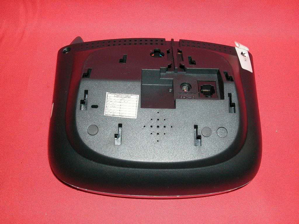
Click to zoom
Application Details
- Equipment Class
- DSS - Part 15 Spread Spectrum Transmitter
- Date of Grant
- Jul 23, 2003
- Application Purpose
- Original Equipment
- Date of Application
- Jul 23, 2003
- Equipment Note
- 2.4GHz FHSS Cordless Phone
- Frequency Range
- 2401.05600000 - 2482.27200000
- Company
- Giant Electronics Ltd
- Country
- Hong Kong
Documents & Files
Document Text
Text extracted from the exhibit documents filed with the FCC. Open a document above to read the original.
Users Manual
OLYMPIA ® OL2410 OWNER’S MANUAL PDF created with FinePrint pdfFactory trial version http://www.fineprint.com 2OLYMPIA OL2410 Owner's Manual Copyright © 2002, Wave Industries Ltd. All Rights Reserved. Reproduction, adaptation, or translation without prior written permission is prohibited, except as allowed under the copyright laws. First Edition: July 2002 Trademark Information Olympia ® is a registered trademark of Olympia International Holdings Ltd. Warranty The information contained in this document is subject to change without notice. Wave Industries makes no warranty of any kind with respect to this information. Wave Industries shall not be liable for any direct, indirect, incidental, consequential, or other damage alleged in connection with the furnishing or use of this information. Printed in China PDF created with FinePrint pdfFactory trial version http://www.fineprint.com OLYMPIA OL2410 Owner's Manual3 TABLE OF CONTENTS IMPORTANT SAFETY INSTRUCTIONS.............................................................5 SAFETY INSTRUCTIONS FOR BATTERIES......................................................7 1Features...........................................................................................................8 2Layout of Keys and Indicators......................................................................10 2.1 Key Functions.........................................................................10 2.2 LCD Display Indications.......................................................12 3Installation and Charging of the Battery Pack..............................................13 4Handset Registration Procedure....................................................................15 5Display Messages & Audio Alert.................................................................16 5.1 Display Message.....................................................................16 5.2 Audible Alerting....................................................................18 6Operation Guide...........................................................................................19 6.1 Making External Calls...........................................................19 6.2 Redialing.................................................................................20 6.3 Receiving Calls......................................................................20 6.4 Flash......................................................................................21 6.5 Page Call................................................................................21 6.6 Making Internal Calls............................................................22 6.7 Call Toggling.........................................................................22 6.8 Call Transfer/Forward...........................................................23 6.9 Call Back...............................................................................24 6.10 Conference...........................................................................24 6.11 Muting the Microphone.......................................................25 6.12 Call Waiting.........................................................................25 7Menu Structure.............................................................................................27 7.1 Call Log.................................................................................28 7.2 Phone Book Operation..........................................................30 7.3 Handset Volume....................................................................34 7.4 Ring Volume.........................................................................34 7.5 Ring Pattern...........................................................................35 7.6 Auto Answer..........................................................................36 7.7 Key Click...............................................................................37 7.8 Key Lock...............................................................................37 7.9 Handset Name.......................................................................39 7.10 Select LANGUAGE............................................................39 7.11 Clear Message Waiting........................................................40 PDF created with FinePrint pdfFactory trial version http://www.fineprint.com 4OLYMPIA OL2410 Owner's Manual 7.12 Dial Method.........................................................................40 8Overview of Telephone Functions................................................................42 9Digital Answering Machine Operation.........................................................47 9.1 DTAM Feature Setup.............................................................47 9.2 About Mailboxes....................................................................54 9.3 About announcement (OGM).................................................57 9.4 DAM Answering...................................................................59 9.5 Volume Control.....................................................................61 9.6 Call screening / intercept........................................................62 9.7 Message Window Display......................................................62 9.8 Remote Control through C/O line..........................................63 10 Consumer Information......................................................................................65 PDF created with FinePrint pdfFactory trial version http://www.fineprint.com OLYMPIA OL2410 Owner's Manual5 IMPORTANT SAFETY INSTRUCTIONS BEFORE USING YOUR TELEPHONE EQUIPMENT, BASIC SAFETY PRECAUTIONS SHOULD ALWAYS BE FOLLOWED TO REDUCE THE RISK OF FIRE, ELECTRIC SHOCK AND INJURY, INCLUDING THE FOLLOWING Read and understand all instructions. Follow all warnings and instructions marked on the product. Unplug this product from the wall outlet before cleaning. Do not use liquid cleaners …
Text truncated - open the document above for the full version.
External Photos
External photos FCC ID: K7G2G4DSS24NS3 External photos FCC ID: K7G2G4DSS24NS3
Internal Photos
Internal photos FCC ID: K7G2G4DSS24NS3 Base assembly (View 1) Base assembly (View 2) Internal photos FCC ID: K7G2G4DSS24NS3 Base assembly (View 3) Base Main PCB comp side Internal photos FCC ID: K7G2G4DSS24NS3 Base Main PCB solder side Base DAM PCB front side Internal photos FCC ID: K7G2G4DSS24NS3 Base DAM PCB rear side Base AC Jack and Telephone Line Jack PCB front side Internal photos FCC ID: K7G2G4DSS24NS3 Base AC Jack and Telephone Line Jack PCB rear side Base Oscillator PCB comp side (View 1) Internal photos FCC ID: K7G2G4DSS24NS3 Base Oscillator PCB comp side (View 2) Base Oscillator PCB comp side (View 3) Internal photos FCC ID: K7G2G4DSS24NS3 Handset assembly Handset Main PCB comp side (View 1) Internal photos FCC ID: K7G2G4DSS24NS3 Handset Main PCB comp side (View 2) Handset Main PCB comp side (View 3) Internal photos FCC ID: K7G2G4DSS24NS3 Handset Main PCB display side Handset Oscillator PCB comp side (View 1) Internal photos FCC ID: K7G2G4DSS24NS3 Handset Oscillator PCB comp side (View 2) Handset Oscillator PCB comp side (View 3) Internal photos FCC ID: K7G2G4DSS24NS3 Handset Oscillator PCB solder side (View 1) Handset Oscillator PCB solder side (View 2) Internal photos FCC ID: K7G2G4DSS24NS3 Handset Oscillator PCB solder side (View 3)
RF Exposure Info
OLYMPIA OL2410 Owner's Manual67 WARNING: Changes or modifications to this unit not expressly approved by the party responsible for compliance could void the user's authority to operate the equipment. CAUTION: To maintain compliance with the FCC's RF exposure guidelines place the base unit at least 20 cm from nearby persons. NOTE: This equipment has been tested and found to comply with the limits for a Class B digital device, pursuant to Part 15 of the FCC Rules. These limits are designed to provide reasonable protection against harmful interference in a residential installation. For body worn operation, this phone has been tested and meets the FCC RF exposure guidelines when used with the belt clip supplied or designated for this product. Use of other accessories may not ensure compliance with FCC RF exposure guidelines. This equipment generates, uses and can radiate radio frequency energy and, if not installed and used in accordance with the instructions, may cause harmful interference to radio communications. However, there is no guarantee that interference will not occur in a particular installation. If this equipment does cause harmful interference to radio or television reception, which can be determined by turning the equipment off and on, the user is encouraged to try to correct the interference by one or more of the following measures: • Reorient or relocate the receiving antenna. • Increase the separation between the equipment and receiver. • Connect the equipment into an outlet on a circuit different from that to which the receiver is needed. • Consult the dealer or an experienced radio TV technician for help. This device complies with part 15 of the FCC rules. Operation is subject to the following two conditions: (1) This device may not cause harmful interference and (2) This device must accept any interference received. Including interference that may cause undesired operation. Privacy of communications may not be ensured when using this phone. PDF created with FinePrint pdfFactory trial version http://www.fineprint.com Intertek Testing Services FCC ID: K7G2G4DSS24NS3 Date: June 18, 2003 For SAR evaluation of the handset, refer to TCB Exclusions List Revised on 17 July 2002. Potable transmitter with output power less than 60/fGHz (d < 2.5cm) can be certified by TCB without the SAR evaluation. In fact, the Output power for portable transmitters is the higher of the conducted or radiated (EIRP) source-based time-averaged output. And the fGHz is mid-band frequency in GHz, and d is the distance to a person’s body, excluding hands, wrists, feet, and ankles. For the tested model of OL2410, the measured peak conducted power was 118.9mW and the source-based time averaged output power was 9.5mW as TX duty cycle of the handset is 8%. The maximum field strength (FS) was 114.7dBμV/m at 2401.056MHz. The distance (D) between the antenna and the equipment under test (EUT) was 3 meters. From these data, the EIRP can be calculated by: EIRP = (FS*D) 2 / 30 = 88.5mW Source-based time averaged output power = (88.5 x 0.08)mW = 7.1mW Based on the above calculation, it is concluded that the handset can be certified by TCB without the SAR evaluation.
Test Report
INTERTEK TESTING SERVICES FCC ID: K7G2G4DSS2NNS3 i LIST OF EXHIBITS INTRODUCTION EXHIBIT 1: Summary of Tests EXHIBIT 2: General Description EXHIBIT 3: System Test Configuration EXHIBIT 4: Measurement Results EXHIBIT 5: Equipment Photographs EXHIBIT 6: Product Labelling EXHIBIT 7: Technical Specifications EXHIBIT 8: Instruction Manual EXHIBIT 9: Security Code Information INTERTEK TESTING SERVICES FCC ID: K7G2G4DSS2NNS3 ii MEASUREMENT/TECHNICAL REPORT Giant Electronics Ltd.- MODEL: OL2410, OL2420, OL2490 FCC ID: K7G2G4DSS24NS3 This report concerns (check one) Original Grant X Class II Change Equipment Type: DSS-Part 15 Spread Spectrum Transmitter Deferred grant requested per 47 CFR 0.457(d)(1)(ii)? Yes No X If yes, defer until : date Company Name agrees to notify the Commission by: date of the intended date of announcement of the product so that the grant can be issued on that date. Transition Rules Request per 15.37? Yes No X If no, assumed Part 15, Subpart C for intentional radiator - the new 47 CFR [08-20-02 Edition] provision. Report prepared by: Tommy Leung Intertek Testing Services 2/F., Garment Centre, 576 Castle Peak Road, Kowloon, Hong Kong. Phone: 852-2173-8538 Fax: 852-2741-1693 INTERTEK TESTING SERVICES FCC ID: K7G2G4DSS2NNS3 iii Table of Contents 1.0 Summary of test results........................................................................................................2 2.0 General Description..................................................................................................................4 2.1 Product Description.................................................................................................................4 2.2 Related Submittal(s) Grants.....................................................................................................5 2.3 Test Methodology...................................................................................................................5 2.4 Test Facility.............................................................................................................................5 3.0 System Test Configuration.......................................................................................................7 3.1 Justification..............................................................................................................................7 3.2 EUT Exercising Software........................................................................................................7 3.3 Support Equipment List and Description..................................................................................8 3.4 Equipment Modification..........................................................................................................9 4.0 Measurement Results.............................................................................................................11 4.1 Maximum Conducted Output Power at Antenna Terminals...................................................11 4.2 Maximum 20 dB RF Bandwidth............................................................................................13 4.3 Minimum Number of Hopping Frequencies..........................................................................15 4.4 Minimum Hopping Channel Carrier Frequency Separation...................................................16 4.5 Average Time of Occupancy.................................................................................................18 4.6 Out of Band Conducted Emissions........................................................................................19 4.7 Out of Band Radiated Emissions...........................................................................................20 4.8 Transmitter Radiated Emissions in Restricted Bands.............................................................21 4.9 Field Strength Calculation.....................................................................................................22 4.10 Radiated Emission Configuration Photograph - Base Unit...................................................23 4.11 Radiated Emission Data - Base Unit....................................................................................24 4.12 Radiated Emission Configuration Photograph - Handset.....................................................28 4.13 Radiated Emission Data - Handset.......................................................................................29 4.14 AC Line Conducted Emission..............................................................................................33 4.15 Line Conducted Configuration Photograph - Base Unit.......................................................34 4.16 Line Conducted Emission Configuration Data.....................................................................35 4.17 Radiated Emission from Digital Section of Transceiver.......................................................36 4.18 Transmitter Duty Cycle Calculation and Measurements....................................................39 5.0 Equipment Photographs.........................................................................................................41 6.0 Product Labelling...................................................................................................................43 7.0 Technical Specifications..........................................................................................................45 8.0 Instruction Manual ................................................................................................................47 9.0 Security Code Information.....................................................................................................49 INTERTEK TESTING SERVICES FCC ID: K7G2G4DSS2NNS3 iv List of attached file Exhibit type File Description filename Test Report Test Report report.pdf Operation Description Technical Description descri.pdf Test Setup Photo Radiated Emission for Base…
Text truncated - open the document above for the full version.
Test Setup Photos
The Worst Case Configuration Photographs FCC ID: K7G2G4DSS24NS3 Radiated Emission – Base Front View Rear View The Worst Case Configuration Photographs FCC ID: K7G2G4DSS24NS3 Radiated Emission – Handset Front View Rear View The Worst Case Configuration Photographs FCC ID: K7G2G4DSS24NS3 Conducted Emission Front View Rear View The Worst Case Configuration Photographs FCC ID: K7G2G4DSS24NS3 Conducted Emission Side View
Contact Information
Applicant
Yumin Zou(A. Manager)
Test Firm
Intertek Testing Services Hong KongBilly Chow
Technical Specifications
| # | Rule Parts | Frequency Range | Power Output |
|---|---|---|---|
| 2 | 15C | 2.40 GHz - 2.48 GHz | 119.00 mW |
Other Applications from Giant Electronics Ltd

K7GMDBJJPR
Jun 24, 2012Two Way Radio - FRS
Equipment Class
FRF - Part 95 Family Radio Face Held Transmitter
K7GMTCEJ
Apr 26, 2012Two Way Radio with GMRS and FRS
Equipment Class
CXX - Communications Rcvr for use w/ licensed Tx and CBs
K7GMDBJJ
Mar 01, 2012Two Way Radio with GMRS and FRS
Equipment Class
FRF - Part 95 Family Radio Face Held Transmitter
K7GMSFGJ
Mar 10, 2011Two Way Radio with Weather Band
Equipment Class
CXX - Communications Rcvr for use w/ licensed Tx and CBs
K7GT2007
Apr 08, 2010Two Way Radio with GMRS and FRS
Equipment Class
FRF - Part 95 Family Radio Face Held Transmitter