K7G2G4DSSL24002.4GHz FH Spread Spectrum Cordless Telephone
Giant Electronics Ltd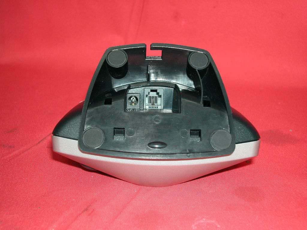
Click to zoom
Application Details
- Equipment Class
- DSS - Part 15 Spread Spectrum Transmitter
- Date of Grant
- Mar 27, 2003
- Application Purpose
- Original Equipment
- Date of Application
- Mar 27, 2003
- Equipment Note
- 2.4GHz FH Spread Spectrum Cordless Telephone
- Frequency Range
- 2401.05600000 - 2482.27200000
- Company
- Giant Electronics Ltd
- Country
- Hong Kong
Documents & Files
Document Text
Text extracted from the exhibit documents filed with the FCC. Open a document above to read the original.
Users Manual
OLYMPIA OL2400 Owner's Manual39 WARNING: Changes or modifications to this unit not expressly approved by the party responsible for compliance could void the user's authority to operate the equipment. CAUTION: To maintain compliance with the FCC's RF exposure guidelines place the base unit at least 20 cm from nearby persons. NOTE: This equipment has been tested and found to comply with the limits for a Class B digital device, pursuant to Part 15 of the FCC Rules. These limits are designed to provide reasonable protection against harmful interference in a residential installation. For body worn operation, this phone has been tested and meets the FCC RF exposure guidelines when used with the belt clip supplied or designated for this product. Use of other accessories may not ensure compliance with FCC RF exposure guidelines. This equipment generates, uses and can radiate radio frequency energy and, if not installed and used in accordance with the instructions, may cause harmful interference to radio communications. However, there is no guarantee that interference will not occur in a particular installation. If this equipment does cause harmful interference to radio or television reception, which can be determined by turning the equipment off and on, the user is encouraged to try to correct the interference by one or more of the following measures: • Reorient or relocate the receiving antenna. • Increase the separation between the equipment and receiver. • Connect the equipment into an outlet on a circuit different from that to which the receiver is needed. • Consult the dealer or an experienced radio TV technician for help. This device complies with part 15 of the FCC rules. Operation is subject to the following two conditions: (1) This device may not cause harmful interference and (2) This device must accept any interference received. Including interference that may cause undesired operation. Privacy of communications may not be ensured when using this phone.
Users Manual
OLYMPIA ® OL2400 OWNER’S MANUAL 2OLYMPIA OL2400 Owner's Manual Copyright © 2002, Wave Industries Ltd. All Rights Reserved. Reproduction, adaptation, or translation without prior written permission is prohibited, except as allowed under the copyright laws. First Edition: July 2002 Trademark Information Olympia ® is a registered trademark of Olympia International Holdings Ltd. Warranty The information contained in this document is subject to change without notice. Wave Industries makes no warranty of any kind with respect to this information. Wave Industries shall not be liable for any direct, indirect, incidental, consequential, or other damage alleged in connection with the furnishing or use of this information. Printed in China OLYMPIA OL2400 Owner's Manual3 TABLE OF CONTENTS IMPORTANT SAFETY INSTRUCTIONS...................................................................................................4 SAFETY INSTRUCTIONS FOR BATTERIES............................................................................................ 5 EQUIPMENT ATTACHMENT LIMITATIONS.......................................................................................... 6 1Features .................................................................................................................................................. 7 2Layout of Keys and Indicators ............................................................................................................... 8 2.1 Key Functions........................................................................................................................................... 8 2.2 LCD Display Indications ......................................................................................................................... 9 3Installation and Charging of the Battery Pack...................................................................................... 10 4Handset Registration Procedure ........................................................................................................... 11 5Display Messages & Audio Alert......................................................................................................... 12 5.1 Display Message..................................................................................................................................... 12 5.2 Audible Alerting.................................................................................................................................... 14 6Operation Guide ................................................................................................................................... 15 6.1 Making External Calls ........................................................................................................................... 15 6.2 Redialing ................................................................................................................................................ 15 6.3 Receiving Calls...................................................................................................................................... 16 6.4 Flash ...................................................................................................................................................... 16 6.5 Page Call................................................................................................................................................ 16 6.6 Making Internal Calls ............................................................................................................................ 17 6.7 Call Toggling......................................................................................................................................... 17 6.8 Call Transfer/Forward ........................................................................................................................... 18 6.9 Call Back ............................................................................................................................................... 19 6.10 Conference........................................................................................................................................... 19 6.11 Muting the Microphone ....................................................................................................................... 19 6.12 Call Waiting ........................................................................................................................................ 19 7Menu Structure ..................................................................................................................................... 21 7.1 Call Log ................................................................................................................................................. 22 7.2 Phone Book Operation .......................................................................................................................... 23 7.3 Handset Volume .................................................................................................................................... 27 7.4 Ring Volume ......................................................................................................................................... 27 7.5 Ring Pattern ........................................................................................................................................... 28 7.6 Auto Answer.......................................................................................................................................... 28 7.7 Key Click............................................................................................................................................... 29 7.8 Key Lock ............................................................................................................................................... 29 7.9 Handset Name ..........…
Text truncated - open the document above for the full version.
Cover Letter(s)
From: [email protected] Sent: Friday, March 28, 2003 1:32 AM To: [email protected] Cc: [email protected] Subject: RE: Giant Electronics Ltd., FCC ID:K7G2G4DSSL2400, AN03T2667 Dear Mike, This mail is in response to your e-mail. 1) The RF exposure statement was already included in the user manual and I have extracted for your review. If it is not OK, please let me know. CAUTION: To maintain compliance with the FCC's RF exposure guidelines place the base unit at least 20 cm from nearby persons. NOTE: This equipment has been tested and found to comply with the limits for a Class B digital device, pursuant to Part 15 of the FCC Rules. These limits are designed to provide reasonable protection against harmful interference in a residential installation. For body worn operation, this phone has been tested and meets the FCC RF exposure guidelines when used with the belt clip supplied or designated for this product. Use of other accessories may not ensure compliance with FCC RF exposure guidelines. operation. 2) The test data of extra charger is attached for your record. 3) Both antennas are transmitting antenna. The picture attached illustrates which antenna is selected when running ant1.bat and ant2.bat respectively in test mode. We used these batch-files and worst case is recorded. When not issuing any batch-file or in normal operation mode, the best one antenna is selected by the handset for each transmit or receive burst based on RSSI level. 4) Please refer to page 7 of the test report for equipment setting. "Analyzer resolution is 100 kHz or greater for frequencies below 1000MHz. The resolution is 1MHz or greater for frequencies above 1000MHz." If you need other information, please feel free to contact me. Best regards, Tommy Leung Supervisor Intertek Testing Services Hong Kong Ltd. ETL SEMKO Tel : 852-2173 8538 Pager : 852-7302 3113 Fax : 852-2741 1693 [email protected] www.etlsemko.com -----Original Message----- From: Mike Kuo [mailto:[email protected]] Sent: Tuesday, March 11, 2003 11:04 AM To: '[email protected]' Cc: Helen Zhao Subject: FW: Giant Electronics Ltd., FCC ID:K7G2G4DSSL2400, AN03T2667 -----Original Message----- From: CERTADM Sent: Monday, March 10, 2003 7:02 PM To: '[email protected]' Subject: Giant Electronics Ltd., FCC ID:K7G2G4DSSL2400, AN03T2667 Notice_content ------------- Question #1: The RF exposure warning statement included in the user manual does not provide enough information to address body worn operation. Please revise the RF exposure statement by considering statement below : "CAUTION: To comply with FCC RF exposure requirements, the base unit should be installed with its antenna located at 20 cm or more from persons and handset should be carried with the specific belt-clip provided for the handset to ensure compliance. Other non-tested belt-clips or similar body-worn accessories may not comply FCC RF exposure requirement, therefore, should be avoided." Question #2: As indicated in the external photo file, there are two types of battery charger. One is equipped with base unit and the other one is for handset use. However, there is one set of AC conducted data was provided but only with one current-carrying measurement. Please provide additional Ac line conducted test data by following ANSI C63.4 section 7 procedures. Question #3: As indicated in the internal photos of handset, it looks like there are two antennas. If there are two antennas in the handset, please indicate which antenna is transmitting antenna or both and indicate the antenna location in the internal photos. Question #4: What is the instrument setting used during above 1GHz and below 1GHz radiated emission measurement ? Best Regards Mike Kuo The items indicated above must be submitted before processing can continue on the above referenced application. Failure to provide the requested information within 60 days of the original e-mail date may result in application dismissal and forfeiture of the filing fee. Also, please note that partial responses increase processing time and should not be submitted. Any questions about the content of this correspondence should be directed to the e-mail address listed below the name of the sender. Your Global Partners in Quality ________________________________________________________________ Confidentiality Notice: All information or opinions expressed in this message and/or any attachments are those of the author and are not necessarily those of Intertek Testing Services or its associated companies. Intertek Testing Services accepts no responsibility for loss or damage arising from its use, including damage from virus. Any personal data contained in this e-mail is treated with the strictest confidence. If you have received this message in error, please notify us immediately and delete it from your system. Our privacy policy can be found at http://www.itslabtest.com/home/privacy.htm Please note that any direct business correspondence contained in this e-mail is subject to our business Terms & Conditions available upon request from the sender.
External Photos
External photos FCC ID: K7G2G4DSSL2400 External photos FCC ID: K7G2G4DSSL2400
Internal Photos
Internal photos FCC ID: K7G2G4DSSL2400 Base assembly (View 1) Base assembly (View 2) Internal photos FCC ID: K7G2G4DSSL2400 Base Main PCB comp side Base Main PCB solder side Internal photos FCC ID: K7G2G4DSSL2400 Base Page key PCB front side Base Page key PCB rear side Internal photos FCC ID: K7G2G4DSSL2400 Base Oscillator PCB comp side Handset assembly Internal photos FCC ID: K7G2G4DSSL2400 Handset Main PCB comp side (View 1) Handset Main PCB comp side (View 2) Internal photos FCC ID: K7G2G4DSSL2400 Handset Main PCB comp side (View 3) Handset Main PCB display side Internal photos FCC ID: K7G2G4DSSL2400 Handset Oscillator PCB comp side (view 1) Handset Oscillator PCB comp side (view 2) Internal photos FCC ID: K7G2G4DSSL2400 Handset Oscillator PCB comp side (view 3) Handset Oscillator PCB solder side (view 1) Internal photos FCC ID: K7G2G4DSSL2400 Handset Oscillator PCB solder side (view 2) Handset Oscillator PCB solder side (view 3)
RF Exposure Info
in accordance with the requirements of FCC Report and Order: ET Docket 93-62, and OET Bulletin 65 Supplement C for 2.4 GHz Frequency Hopping Spread Spectrum Cordless Phone MODEL: OL2400 FCC ID: K7G2G4DSSL2400 February 28, 2003 REPORT NO: 03I1843-1 Prepared for Giant Electronics Ltd 7/F, Elite Industrial Building, 135-137 Hoi Bun Road Kwun Tong, Hong Kong Prepared by COMPLIANCE CERTIFICATION SERVICES 561F MONTEREY ROAD, MORGAN HILL, CA 95037, USA TEL: (408) 463-0885 REPORT NO: 03I1843-1 DATE: February 28, 2003 FCC ID: K7G2G4DSSL2400 COMPLIANCE CERTIFICATION SERVICES Page: 2 of 25 This report shall not be reproduced except in full, without the written approval of CCS. This document may be altered or revised by Compliance Certification Services personnel only, and shall be noted in the revision section of the document. CERTIFICATE OF COMPLIANCE (SAR EVALUATION) DATES OF TEST: February 28, 2003 REPORT NO: 03I1843-1 APPLICANT: Giant Electronics Ltd 7/F, Elite Industrial Building, 135-137 Hoi Bun Road Kwun Tong, Hong Kong MODEL: OL2400 FCC ID: K7G2G4DSSL2400 DEVICE CATEGORY: PORTABLE DEVICES EXPOSURE CATEGORY: GENERAL POPULATION/UNCONTROLLED EXPOSURE Test Sample is a: Production unit Modulation type: Frequency Hopping Spread Spectrum (FHSS) Operating Mode: Maximum continuous output Tx Frequency: 2401 ~ 2482 MHz Max. O/P Power: 22.53 dBm (Conducted) Max. SAR (1g): 0.0239 W/Kg (at 2401 MHz, Right Head - touched position) 0.0917 W/Kg (at 2401 MHz, Body worn) Application Type: Certification FCC Rule Part(s): 15.247 This wireless portable device has been shown to be capable of compliance for localized specific absorption rate (SAR) for uncontrolled environment/general population exposure limits specified in ANSI/IEEE Std. C95.1-1992 and had been tested in accordance with the measurement procedures specified in FCC OET 65 Supplement C (released on 6/29/2001 see Test Report). I attest to the accuracy of data. All measurements reported herein were performed by me or were made under my supervision and are correct to the best of my knowledge and belief. I assume full responsibility for the completeness of these measurements and vouch for the qualifications of all persons taking them. Steve Cheng EMC Engineering Manager REPORT NO: 03I1843-1 DATE: February 28, 2003 FCC ID: K7G2G4DSSL2400 COMPLIANCE CERTIFICATION SERVICES Page: 3 of 25 This report shall not be reproduced except in full, without the written approval of CCS. This document may be altered or revised by Compliance Certification Services personnel only, and shall be noted in the revision section of the document. TABLE OF CONTENT 1. EUT DESCRIPTION................................................................................................................4 2. REQUIREMENTS FOR COMPLIANCE TESTING DEFINED BY THE FCC........................5 3. DOSIMETRIC ASSESSMENT SETUP...................................................................................5 3.1. MEASUREMENT SYSTEM DIAGRAM....................................................................................................................6 3.2. SYSTEM COMPONENTS...........................................................................................................................................7 4. EVALUATION PROCEDURE.................................................................................................9 5. MEASUREMENT UNCERTAINTY.......................................................................................12 6. EXPOSURE LIMIT................................................................................................................13 7. EUT ARRANGEMENT..........................................................................................................14 8. MEASUREMENT RESULTS................................................................................................15 8.1. SYSTEM VALIDATION..............................................................................................................................................15 8.2. TEST LIQUID CONFIRMATION..............................................................................................................................16 8.3. EUT TUNE-UP PROCEDURE.................................................................................................................................17 8.4. EUT SETUP PHOTOS..............................................................................................................................................18 8.5. SAR MEASUREMENT RESULTS...........................................................................................................................21 9. EUT PHOTOS........................................................................................................................22 10. EQUIPMENTS LIST & CALIBRATION INFORMATION.....................................................23 11. REFERENCES......................................................................................................................24 12. ATTACHMANTS...................................................................................................................25 REPORT NO: 03I1843-1 DATE: February 28, 2003 FCC ID: K7G2G4DSSL2400 COMPLIANCE CERTIFICATION SERVICES Page: 4 of 25 This report shall not be reproduced except in full, without the written approval of CCS. This document may be altered or revised by Compliance Certification Services personnel only, and shall be noted in the revision section of the document. 1. EUT DESCRIPTION APPLICANT: Giant Electronics Ltd 7/F, Elite Industrial Building, 135-137 Hoi Bun Road Kwun Tong, Hong Kong MODEL: OL2400 FCC ID: K7G2G4DSSL2400 DEVICE CATEGORY: PORTABLE DEVICES EXPOSURE CATEGORY: GENERAL POPULATION/UNCONTROLLED EXPOSURE Test Sample is a: Production unit Modulation type: Frequency Hopping Spread Spectrum (FHSS) Operating Mode: Maximum continuous output Tx Frequency: 2401 ~ 2482 MHz Max. O/P Power: 22.53 dBm (Conducte…
Text truncated - open the document above for the full version.
RF Exposure Info
Date/Time: 02/28/03 10:57:54 Test Laboratory: Compliance Certification Services File Name: D2450V2 SN 1577_12.6mW.da4 DUT: Dipole Type & Serial Number: D2450V2 SN 706 Program: System Validation - ET3V6 SN 1577; Input Power 250mW Communication System: CW - 2450 MHz; Frequency: 2450 MHz; Duty Cycle: 1:1 Medium: Head 2450 MHz ( σ = 1.8618 mho/m, ε = 39.45, ρ = 1000 kg/m3) Phantom section: FlatSection DASY4 Configuration: - Probe: ET3DV6 - SN1577; ConvF(5.1, 5.1, 5.1); Calibrated: 2/7/2003 - Sensor-Surface: 4mm (Mechanical Surface Detection) - Electronics: DAE3 Sn427; Calibrated: 2/4/2003 - Phantom: SAM 2 - TP:1050 - Software: DASY4, V4.0 Build 51 Zoom Scan (5x5x7)/Cube 0: Measurement grid: dx=7.5mm, dy=7.5mm Reference Value = 92.2 V/m Peak SAR = 27.5 mW/g SAR(1 g) = 12.6 mW/g; SAR(10 g) = 5.57 mW/g Power Drift = -0.006 dB Area Scan (9x9x1): Measurement grid: dx=10mm, dy=10mm SAR in dB -23 -20.7 -18.4 -16.1 -13.8 -11.5 -9.2 -6.9 -4.6 -2.3 0
RF Exposure Info
Date/Time: 02/28/03 13:50:16 Test Laboratory: Compliance Certification Services File Name: 1L-CH_0.018mW.da4 EUT Setup Configuration 1 ( Left Head ) SAR in dB -21.2 -19.1 -17 -14.8 -12.7 -10.6 -8.48 -6.36 -4.24 -2.12 0 Date/Time: 02/28/03 13:50:16 Test Laboratory: Compliance Certification Services File Name: 1L-CH_0.018mW.da4 DUT: Giant Type & Serial Number: OL2400 Program: Left Touched; Low channel (2401 MHz) Communication System: FHSS - Giant; Frequency: 2401 MHz; Duty Cycle: 1:12.5 Medium: Head 2450 MHz ( σ = 1.8618 mho/m, ε = 39.45, ρ = 1000 kg/m3) Phantom section: LeftSection DASY4 Configuration: - Probe: ET3DV6 - SN1577; ConvF(5.1, 5.1, 5.1); Calibrated: 2/7/2003 - Sensor-Surface: 4mm (Mechanical Surface Detection) - Electronics: DAE3 Sn427; Calibrated: 2/4/2003 - Phantom: SAM 2 - TP:1050 - Software: DASY4, V4.0 Build 51 Zoom Scan (5x5x7)/Cube 0: Measurement grid: dx=7.5mm, dy=7.5mm Reference Value = 3.26 V/m Peak SAR = 0.0377 mW/g SAR(1 g) = 0.018 mW/g; SAR(10 g) = 0.00848 mW/g Power Drift = -0.12 dB Area Scan (15x11x1): Measurement grid: dx=10mm, dy=10mm SAR in dB -21.2 -19.1 -17 -14.8 -12.7 -10.6 -8.48 -6.36 -4.24 -2.12 0 Date/Time: 02/28/03 14:23:34 Test Laboratory: Compliance Certification Services File Name: 2M-CH_0.0162mW.da4 DUT: Giant Type & Serial Number: OL2400 Program: Left Touched; Middle channel (2442MHz) Communication System: FHSS - Giant; Frequency: 2442 MHz; Duty Cycle: 1:12.5 Medium: Head 2450 MHz ( σ = 1.8618 mho/m, ε = 39.45, ρ = 1000 kg/m3) Phantom section: LeftSection DASY4 Configuration: - Probe: ET3DV6 - SN1577; ConvF(5.1, 5.1, 5.1); Calibrated: 2/7/2003 - Sensor-Surface: 4mm (Mechanical Surface Detection) - Electronics: DAE3 Sn427; Calibrated: 2/4/2003 - Phantom: SAM 2 - TP:1050 - Software: DASY4, V4.0 Build 51 Zoom Scan (5x5x7)/Cube 0: Measurement grid: dx=7.5mm, dy=7.5mm Reference Value = 2.86 V/m Peak SAR = 0.0339 mW/g SAR(1 g) = 0.0162 mW/g; SAR(10 g) = 0.00754 mW/g Power Drift = -0.12 dB Area Scan (15x11x1): Measurement grid: dx=10mm, dy=10mm SAR in dB -24.2 -21.8 -19.3 -16.9 -14.5 -12.1 -9.67 -7.25 -4.84 -2.42 0 Date/Time: 02/28/03 16:06:32 Test Laboratory: Compliance Certification Services File Name: 3H-CH_0.0134mW.da4 DUT: Giant Type & Serial Number: OL2400 Program: Left Touched; High channel (2482MHz) Communication System: FHSS - Giant; Frequency: 2482 MHz; Duty Cycle: 1:12.5 Medium: Head 2450 MHz ( σ = 1.8618 mho/m, ε = 39.45, ρ = 1000 kg/m3) Phantom section: LeftSection DASY4 Configuration: - Probe: ET3DV6 - SN1577; ConvF(5.1, 5.1, 5.1); Calibrated: 2/7/2003 - Sensor-Surface: 4mm (Mechanical Surface Detection) - Electronics: DAE3 Sn427; Calibrated: 2/4/2003 - Phantom: SAM 2 - TP:1050 - Software: DASY4, V4.0 Build 51 Zoom Scan (5x5x7)/Cube 0: Measurement grid: dx=7.5mm, dy=7.5mm Reference Value = 2.75 V/m Peak SAR = 0.0279 mW/g SAR(1 g) = 0.0134 mW/g; SAR(10 g) = 0.00624 mW/g Power Drift = -0.02 dB Area Scan (15x11x1): Measurement grid: dx=10mm, dy=10mm SAR in dB -50 -45 -40 -35 -30 -25 -20 -15 -10 -5 0 Date/Time: 02/28/03 16:43:28 Test Laboratory: Compliance Certification Services File Name: 1L-CH_0.0137mW.da4 DUT: Giant Type & Serial Number: OL2400 Program: Left Touched; Low channel (2401MHz) Communication System: FHSS - Giant; Frequency: 2401 MHz; Duty Cycle: 1:12.5 Medium: Head 2450 MHz ( σ = 1.8618 mho/m, ε = 39.45, ρ = 1000 kg/m3) Phantom section: LeftSection DASY4 Configuration: - Probe: ET3DV6 - SN1577; ConvF(5.1, 5.1, 5.1); Calibrated: 2/7/2003 - Sensor-Surface: 4mm (Mechanical Surface Detection) - Electronics: DAE3 Sn427; Calibrated: 2/4/2003 - Phantom: SAM 2 - TP:1050 - Software: DASY4, V4.0 Build 51 Zoom Scan (5x5x7)/Cube 0: Measurement grid: dx=7.5mm, dy=7.5mm Reference Value = 2.56 V/m Peak SAR = 0.0288 mW/g SAR(1 g) = 0.0137 mW/g; SAR(10 g) = 0.00647 mW/g Power Drift = -0.08 dB Area Scan (14x10x1): Measurement grid: dx=10mm, dy=10mm SAR in dB -20.1 -18.1 -16.1 -14.1 -12 -10 -8.03 -6.02 -4.02 -2.01 0 Date/Time: 02/28/03 17:15:28 Test Laboratory: Compliance Certification Services File Name: 2M-CH_0.0123mW.da4 DUT: Giant Type & Serial Number: OL2400 Program: Left Touched; Middle channel (2442MHz) Communication System: FHSS - Giant; Frequency: 2442 MHz; Duty Cycle: 1:12.5 Medium: Head 2450 MHz ( σ = 1.8618 mho/m, ε = 39.45, ρ = 1000 kg/m3) Phantom section: LeftSection DASY4 Configuration: - Probe: ET3DV6 - SN1577; ConvF(5.1, 5.1, 5.1); Calibrated: 2/7/2003 - Sensor-Surface: 4mm (Mechanical Surface Detection) - Electronics: DAE3 Sn427; Calibrated: 2/4/2003 - Phantom: SAM 2 - TP:1050 - Software: DASY4, V4.0 Build 51 Zoom Scan (5x5x7)/Cube 0: Measurement grid: dx=7.5mm, dy=7.5mm Reference Value = 2.42 V/m Peak SAR = 0.0285 mW/g SAR(1 g) = 0.0123 mW/g; SAR(10 g) = 0.00564 mW/g Power Drift = -0.12 dB Area Scan (14x10x1): Measurement grid: dx=10mm, dy=10mm SAR in dB -50 -45 -40 -35 -30 -25 -20 -15 -10 -5 0 Date/Time: 02/28/03 17:57:56 Test Laboratory: Compliance Certification Services File Name: 3H-CH_0.0116mW.da4 DUT: Giant Type & Serial Number: OL2400 Program: Left Tilt; High channel (2482MHz) Communication System: FHSS - Giant; Frequency: 2482 MHz; Duty Cycle: 1:12.5 Medium: Head 2450 MHz ( σ = 1.8618 mho/m, ε = 39.45, ρ = 1000 kg/m3) Phantom section: LeftSection DASY4 Configuration: - Probe: ET3DV6 - SN1577; ConvF(5.1, 5.1, 5.1); Calibrated: 2/7/2003 - Sensor-Surface: 4mm (Mechanical Surface Detection) - Electronics: DAE3 Sn427; Calibrated: 2/4/2003 - Phantom: SAM 2 - TP:1050 - Software: DASY4, V4.0 Build 51 Zoom Scan (5x5x7)/Cube 0: Measurement grid: dx=7.5mm, dy=7.5mm Reference Value = 2.45 V/m Peak SAR = 0.0245 mW/g SAR(1 g) = 0.0116 mW/g; SAR(10 g) = 0.00543 mW/g Power Drift = -0.1 dB Area Scan (14x10x1): Measurement grid: dx=10mm, dy=10mm SAR in dB -50 -45 -40 -35 -30 -25 -20 -15 -10 -5 0 Date/Time: 02/28/03 18:36:26 Test Laboratory: Compliance Certification Services File Name: 1L-CH_0.0239mW.da4 EUT Setup Configuration 2 ( Right Head ) SAR in dB -23 -20.7 -18.4 -16.1 -13.8 -11.5 -9.21 -6.91 -4.6 -2.3 0 Date/Time: 02/28/03 18:36:26 T…
Text truncated - open the document above for the full version.
RF Exposure Info
Spectrum plots to demonstrate the duty cycle that was used during the tests Duty Cycle: 100 (0.8/0.988) = 8.09 %
Test Report
• The test results reported in this report shall refer only to the sample actually tested and shall not refer or be deemed to refer to bulk from which such a sample may be said to have been obtained. • This report shall not be reproduced except in full without prior authorization form Giant Electronics Limited Limited FCC ID: K7G2G4DSSL2400 Intertek Testing Services Hong Kong Ltd. 2/F., Garment Centre, 576 Castle Peak Road, Kowloon, Hong Kong. Tel: (852) 2173 8888 Fax: (852) 2741 1693 Giant Electronics Limited Application For Certification 2.4GHz Frequency Hopping Spread Spectrum Cordless Phone with Caller ID (FCC ID: K7G2G4DSSL2400) WO# 03014781 TL/Ann Choy February 26, 2003 INTERTEK TESTING SERVICES FCC ID: K7G2G4DSSL2400 i LIST OF EXHIBITS INTRODUCTION EXHIBIT 1: Summary of Tests EXHIBIT 2: General Description EXHIBIT 3: System Test Configuration EXHIBIT 4: Measurement Results EXHIBIT 5: Equipment Photographs EXHIBIT 6: Product Labelling EXHIBIT 7: Technical Specifications EXHIBIT 8: Instruction Manual EXHIBIT 9: Security Code Information INTERTEK TESTING SERVICES FCC ID: K7G2G4DSSL2400 ii MEASUREMENT/TECHNICAL REPORT Giant Electronics Limited- MODEL: OL2400 FCC ID: K7G2G4DSSL2400 This report concerns (check one) Original Grant X Class II Change Equipment Type: DSS-Part 15 Spread Spectrum Transmitter Deferred grant requested per 47 CFR 0.457(d)(1)(ii)? Yes No X If yes, defer until : date Company Name agrees to notify the Commission by: date of the intended date of announcement of the product so that the grant can be issued on that date. Transition Rules Request per 15.37? Yes No X If no, assumed Part 15, Subpart C for intentional radiator - the new 47 CFR [08-20-02 Edition] provision. Report prepared by: Tommy Leung Intertek Testing Services 2/F., Garment Centre, 576 Castle Peak Road, Kowloon, Hong Kong. Phone: 852-2173-8538 Fax: 852-2741-1693 INTERTEK TESTING SERVICES FCC ID: K7G2G4DSSL2400 iii Table of Contents 1.0 Summary of test results ...................................................................................................... 2 2.0 General Description..................................................................................................................4 2.1 Product Description .................................................................................................................4 2.2 Related Submittal(s) Grants .....................................................................................................5 2.3 Test Methodology....................................................................................................................5 2.4 Test Facility.............................................................................................................................5 3.0 System Test Configuration ................................................…
Text truncated - open the document above for the full version.
Contact Information
Applicant
Yumin Zou(A. Manager)
Test Firm
Intertek Testing Services Hong KongBilly Chow
Technical Specifications
| # | Rule Parts | Frequency Range | Power Output |
|---|---|---|---|
| 2 | 15C | 2.40 GHz - 2.48 GHz | 119.00 mW |
Other Applications from Giant Electronics Ltd

K7GMDBJJPR
Jun 24, 2012Two Way Radio - FRS
Equipment Class
FRF - Part 95 Family Radio Face Held Transmitter
K7GMTCEJ
Apr 26, 2012Two Way Radio with GMRS and FRS
Equipment Class
CXX - Communications Rcvr for use w/ licensed Tx and CBs
K7GMDBJJ
Mar 01, 2012Two Way Radio with GMRS and FRS
Equipment Class
FRF - Part 95 Family Radio Face Held Transmitter
K7GMSFGJ
Mar 10, 2011Two Way Radio with Weather Band
Equipment Class
CXX - Communications Rcvr for use w/ licensed Tx and CBs
K7GT2007
Apr 08, 2010Two Way Radio with GMRS and FRS
Equipment Class
FRF - Part 95 Family Radio Face Held Transmitter