K7GFV200FRS+GMRS
Giant Electronics Ltd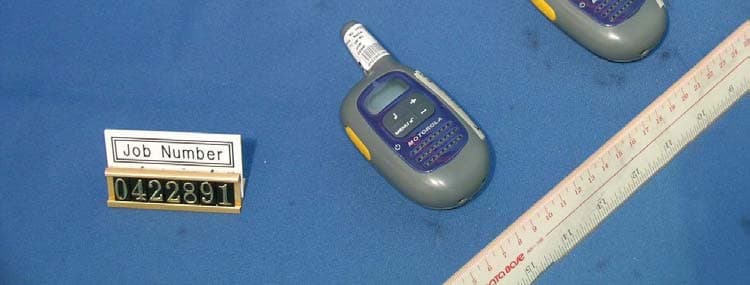
Click to zoom
Application Details
- Equipment Class
- FRF - Part 95 Family Radio Face Held Transmitter
- Date of Grant
- Feb 03, 2005
- Application Purpose
- Original Equipment
- Date of Application
- Feb 03, 2005
- Equipment Note
- FRS+GMRS
- Frequency Range
- 467.56250000 - 467.71250000
- Company
- Giant Electronics Ltd
- Country
- Hong Kong
Documents & Files
Document Text
Text extracted from the exhibit documents filed with the FCC. Open a document above to read the original.
Users Manual
Two-Way Radio User’s Guide Model FV200 Safety and General InformationFCC Licensing Information Control Buttons KEM-PK15558 Important Information on Safe and Efficient Operation Read This Information Before Using Your Radio. The information provided in this document supersedes the general safety information in user guides published prior to December 1, 2002. Transmit and Receive Procedure Your two-way radio contains a transmitter and a receiver. To control your exposure and ensure compliance with the general population/uncontrolled environment exposure limits, always adhere to the following procedure: • Transmit no more than 50% of the time. • To receive calls, release the PTT button. • To transmit (talk), press the Push to Talk (PTT) button. Transmitting 50% of the time, or less, is important because the radio generates measurable RF energy exposure only when transmitting (in terms of measuring standards compliance). Exposure to Radio Frequency Energy Your Motorola two-way radio complies with the following RF energy exposure standards and guidelines: • United States Federal communications Commission, Code of Federal Regulations; 47CFR part 2 sub-part J • American National Standards Institute (ANSI)/Institute of Electrical and Electronic Engineers (IEEE) C95. 1-1992 • Institute of Electrical and Electronics Engineers (IEEE) C95.1-1999 Edition • International Commission on Non-Ionizing Radiation Protection (ICNIRP) 1998 Getting Started Display Screen Guide Installing the Batteries: Your radio uses three AAA Alkaline batteries and beeps when the batteries are low. 1. Turn the radio off. 2. With the back of the radio facing you, use the belt clip or a coin to wedge the battery cover open. 3. Insert three AAA Alkaline batteries as shown on the inside of the battery compartment. 4. Reposition the battery cover and press down to secure. NOTE:The FV200 model radio can use a NiMh rechargeable battery instead of three AAA batteries. A rechargeable battery upgrade kit is available with the rechargeable version. Installing the NiMh Battery Pack: 1. Turn the radio off. 2. Follow step 2 above to remove the battery cover. 3. Remove the battery pack from the clear plastic bag. Do not disassemble or unwrap the battery pack. 4. Insert the NiMh battery pack so the “This Side Up” is showing. 5. Reposition the battery cover and press down to secure. Battery Meter The battery icon shows the battery charge level, from full [icon] to empty [icon]. When the battery is empty, the radio chirps periodically after releasing PTT. The radio powers off when the voltage drops below a predetermined level to protect the rechargeable battery. Note:Remove the batteries before storing your radio for extended periods of time. Batteries corrode over time and may cause permanent damage to your radio. Talking and Listening 1. To talk, press and hold PTT. 2. When you are finished talking, release PTT. For maximum clarity, hold the radio two to three inches away from your mouth and speak directly into the microphone. Do not cover the microphone while talking. Talk Range Your radio is designed to maximize performance and improve transmission range. Do not use the radios closer than five feet apart Push to Talk Timeout Timer To prevent accidental transmissions and save battery life, the radio emits a continuous warning tone and stops transmitting if you press PTT for 60 continuous seconds. Low Battery Alert In addition to your battery meter showing how much battery power you have, your radio will beep to alert you to the fact that your batteries are low. Recharging NiMh Battery Pack (optional accessory) 1. Follow steps 1-5 for installing the NiMh battery pack. 2. Plug the AC power adapter into the AC adapter plug on the side of the radio. 3. Plug the AC power adapter into the wall Notes: • The light on AC power adapter will glow continuously when radio/battery is connected. • When moving between hot and cold temperatures, do not charge the battery until the battery temperature acclimates (usually about 20 minutes). • For optimal battery life, unplug the radio from the AC power adapter within 16 hours. • When your radio is plugged into the AC power adapter, your radio will not work. Turning Your Radio On and Off To turn on,press and hold MENU until a channel number appears and the radio beeps. To turn off,press and hold MENU until the radio beeps and the display goes blank. Adjusting the Volume Press + to increase or – to decrease the volume. The volume level flashes and VOL displays. Attaching and Removing the Belt Clip Hook the belt clip into the notch at the top of the radio and slide down until it clicks into place. To remove, press locking tab back and lift up. Initial Setup Selecting the Channel The channel is the frequency your radio uses to transmit. Your radio has 22 channels. 1. Briefly press and release MENU. The channel number flashes. 2. Press + or – to select a channel. 3. Press PTT to confirm or MENU to continue set up. Manufactured, distributed or sold by Giant International Ltd., official licensee for this product. Motorola, the Motorola logo trademarks and the Motorola trade dress are owned by Motorola, Inc. and are used under license from Motorola, Inc. Please contact Giant International Ltd. at 800-638-5119 for questions/comments, warranty, support, or service related to this product. MOTOROLA and the Stylized M Logo are registered in the U.S. Patent & Trademark Office. All other product or service names are the property of their respective owners. © Motorola, Inc. 2004. Patent and Copyright Information For More Information For further information, you may call Motorola at 1-800-638-5119 (U.S. and Canada) or visit us on the Internet at http://www.motorola.com. Setting and Transmitting Call Tones Your radio has 10 different call tones that you can transmit to other radios in your group to alert them that you want to talk. To set a call tone: 1. With the radio on, short press MENU until the _ appears. The current ca…
Text truncated - open the document above for the full version.
Cover Letter(s)
The content of this document is Giant Electronics Ltd.'s intellectual property and is the property of Giant. It is to be treated as strictly confidential and is not to Re: FCC ID: K7GFV200 Pursuant to 47 CFR 0.459, Giant Electronics Ltd. request confidential protection of the following documents submitted electronically in furtherance of the above-reference application as containing propriety information listed below: ■ Schematic ■ Block Diagram ■ Operational Description This information represents intellectual property of Giant Electronics Ltd. and it is subject to competition. This information should not be made routinely available for public inspection, and Giant Electronics Ltd. reserves the right to discern which parties can obtain access to this information. Dated this 13th day of January 2005 By : YK Ling . Signature Printed Title : Electronic Engineer Confidentiality Request Letter be disclosed, reproduced, or used except as authorized in writing by Giant Electronics Ltd. In connection with the manufacture, maintenance and use of the Giant equipment to which it pertains. Copyright @Giant Electronics Ltd. All rights reserved.
External Photos
Test Setup FCC ID : K7GFV200 External Photo - front External Photo - rear
ID Label/Location Info
Label Location FCC ID : K7GFV200 The label content and size will follow the specification of page1 in this file.
Internal Photos
Test Setup FCC ID : K7GFV200 Internal Photo - 1 Internal Photo - 2 Test Setup FCC ID : K7GFV200 Internal Photo - 3 Internal - Photo 4 Test Setup FCC ID : K7GFV200 Internal - Photo 5
Parts List/Tune Up Info
Giant Electronics Ltd. Parent FV200XXXUSGY04 FRS RADIO GRAY TG EA 1 FV200BAXUSGYXA BASE UNIT GRAY SA 2 EA 0.2 FV200BCXUSGYXA BASE CASING GRAY SA 1 EA ..3 FV200BCXXX BASE CASING COMMON SA 1 EA...4 KEJW-SA30BK STRAND WIRE UL1007 #30 BLACK EN 0.035 M JW201...4 KEJW-SA30RD STRAND WIRE UL1007 #30 RED EN 0.03 M JW202...4 KEM-M15501 CONTACT A MA 1 EA...4 KEM-M15502 CONTACT B MA 1 EA...4 KEM-M15503 CONTACT C MA 1 EA...4 KEM-M15504 CONTACT D MA 1 EA...4 KEM-M15505 LCD BRACKET MA 1 EA...4 KEM-M15506 ANTENNA WIRE MA 1 EA...4 KEM-M9752 SHIELD CAN MA 1 EA E507...4 KEM-OT15501 KEYPAD MC 1 EA...4 KEM-OT15502 PTT BUTTON MC 1 EA...4 KEM-OT15503 SCREW COVER (COOL GRAY 8U) MC 1 EA...4 KEM-OT15504 METAL DOME MC 1 EA...4 KEM-OT15505 ZEBRA MC 1 EA...4 KEM-OT15506 PROTECTIVE FILM MC 1 EA E503...4 KEM-OT7357 SPEAKER SPONGE MC 1 EA...4 KEM-OT7358 SPONGE CUSHION MC 1 EA...4 KEM-OT9753 PTT METAL DOME MC 1 EA...4 KEM-OT9755 SPEAKER NET MC 1 EA E504...4 KEM-OT9757 TAPE FOR METAL DOME MC 1 EA...4 KEM-OT9758 PVC SHEET MC 1 EA E503...4 KEM-OT9760 CUSHION FOR FILTER MC 1 EA...4 KEM-OT9761 PVC SHEET FOR PTT PCB MC 1 EA...4 KEM-OT9763 CUSHION IN ANTENNA MC 1 EA E503...4 KEM-P15506A LCD HOLDER MD 1 EA E503...4 KEM-TS2306X4B TAPTITE SCREW X/HD T2.3X6 ML 5 EA E503...4 KESP-122-1 SPEAKER 32 OHM 0.5W 3632A505 EV 1 EA SPK1...4 KESP-172 MIC DB MIC C9745 42dB EV 1 EA MIC1..3 FV200BC1USSV BASE CASING US SILVER SA 1 EA...4 KEM-P15504A-02 FACE PLATE WITH PRINTING SA 1 EA....5 KEM-P15504A FACE PLATE WITHOUT PRINTING MD 1 EA....5 KEM-P15504A-02Z PRINTING FOR FACE PLATE MD 1 EA..3 FV200BC4GY BASE CASING GRAY SA 1 EA...4 KEM-P15501A FRONT CABINET ME 1 EA E503...4 KEM-P15502A REAR CABINET ME 1 EA E503...4 KEM-P15503A BATTERY DOOR MD 1 EA E503...4 KEM-P15505A BELT CLIP MD 1 EA E504 0.2 FV200B1XUSXXXX BASE RF & MAIN PCB US SA 1 EA ..3 FV2CCB1XXXC BASE RF & MAIN COMMON PART SA 1 EA...4 FV2CCB1SC BASE RF & MAIN COMMON SMT PART SA 1 EA....5 KCC-TR003-A CAP.CHIP TR1 10P ECRJA010A11 PANASONIC EA 1 EA C53....5 KCC-100FDNPOMUG CAP.CER.CHIP 50V D% 10PF NPO MURATA EA 2 EA C21,C17....5 KCC-101FJCOGGNG CAP CER CHIP 50V COG +/-5% 100PF EYANG EA 22 EA C1,C40,C44,C45,C57,C58,C7,C98,C114,C121,C96,C127 C128,C129,C140,C141,C151,C75,C5,C69,C88,C9 ....5 KCC-101FJNPOMUG CAP.CER.CHIP 50V CH J% 100PF MURATA EA 0 EA C1,C40,C44,C45,C57,C58,C7,C98,C114,C121,C96,C127 FV200 BOM.xls...FV200XXXUSGY04 BOM 2005-1-11 1 of 5 Giant Electronics Ltd. C128,C129,C140,C141,C151,C75,C5,C69,C88,C9 ....5 KCC-101FJNPOMUG CAP.CER.CHIP 50V CH J% 100PF MURATA EA 3 EA C92,C37,C18....5 KCC-101FRJU2JE CAP. CER. CHIP 50V U2J J% 100PF EA 1 EA C74....5 KCC-102FKBMUG CAP.CER.CHIP 50V B K% 0.001UF MURATA EA 5 EA C12,C87,C131,C115,C52....5 KCC-103DKBMUG CAP. CER. CHIP 16V X7R K 0.01UF EA 2 EA C77,C97....5 KCC-104DRKBE CAP. CER. CHIP 16V B K% 0.1UF EA 1 EA C42....5 KCC-104DZFEYG CAP CER CHIP 16V Y5V Z 0.1uF EYANG EA 15 EA C11,C28,C61,C63,C66,C112,C117,C139,C82,C89,C119 C49,C93,C142,C43 ....5 KCC-104DZFMUG CAP.CER.CHIP 16V F Z% 0.1UF MURATA EA 0 EA C11,C28,C61,C63,C66,C112,C117,C139,C82,C89,C119 C49,C93,C142 ....5 KCC-105DRZFB CAP. CER. CHIP 16V F Z% 1UF EA 1 EA C106....5 KCC-105DRZFM CAP. CER. CHIP 16V F Z% 1UF EA 2 EA C68,C94....5 KCC-106BRZFF CAP CER CHIP 10V F Z 10UF EA 3 EA C73,C122,C27....5 KCC-109FBCOGMUG CAP. CHIP 50V COG +/-0.1P 1PF 0402 EA 1 EA C31....5 KCC-120FJNPOMUG CAP.CER.CHIP 50V CH J% 12PF MURATA EA 3.25 EA C4,C14,C23,C70 FOR MATCH YELLOW CRYSTAL....5 KCC-129FBCOGMUG CAP. CHIP 50V COG +/-0.1P 1.2PF 0402 EA 1 EA C30....5 KCC-150FJNPOMUG CAP.CER.CHIP 50V CH J% 15PF MURATA EA 1 EA C3....5 KCC-152FKBMUG CAP CER CHIP 50V X7R K 0.0015UF MURATA EA 1 EA C55....5 KCC-180FJNPOMUG CAP.CER.CHIP 50V CH J% 18PF MURATA EA 2 EA C51,C22....5 KCC-200FJNPOTDG CAP. CER. CHIP 50V J 20PF TDK C1005COG1H EA 0.25 EA C72 FOR MATCH YELLOW CRYSTAL....5 KCC-209FCNPOMUG CAP.CER.CHIP 50V CH C% 2PF MURATA EA 1 EA C25....5 KCC-222ERKX7RE CAP CER CHIP 25V X7R K 2200PF 28295-17 GRM39X7R2 2 EA 1 EA C102 ....5 KCC-222FKBMUG CAP.CER.CHIP 50V B K% 0.0022UF MURATA EA 2 EA C54,C95....5 KCC-223DKBMUG CAP.CER.CHIP 16V B K% 22NF MURATA EA 3 EA C41,C133,C101....5 KCC-240FJNPOMUG CAP.CER.CHIP 50V CH J% 24PF MURATA EA 1 EA C8....5 KCC-270FJNPOMUG CAP. CER. CHIP 50V NPO J 27P 0402 EA 1 EA C62....5 KCC-309FBNPOMUG CAP CER CHIP 50V B NPO 3P EA 2 EA C26,C32....5 KCC-309FCNPOMUG CAP.CER.CHIP 50V CH C% 3PF MURATA EA 1 EA C15....5 KCC-330FJNPOMUG CAP.CER.CHIP 50V CH J% 33PF MURATA EA 0.25 EA C72 FOR MATCH GREEN CRYSTAL....5 KCC-333BRKBG CAP. CER. CHIP 10V B K% 0.033UF EA 2 EA C125,C64....5 KCC-334DRKBM CAP. CER. CHIP 16V B K% 0.33UF EA 2 EA C83,C48....5 KCC-390FJNPOMUG CAP CER CHIP 50V NPO J% 39PF MURATA EA 2 EA C13,C90....5 KCC-391FRJNPOE CAP CER CHIP 50V NPO J 390PF EA 1 EA C91....5 KCC-393BKBMUG CAP. CER. CHIP 10V K X7R 0.039UF 0402 EA 1 EA C60....5 KCC-409FCNPOMUG CAP.CER.CHIP 50V CH C% 4PF MURATA EA 2 EA C24,C34....5 KCC-471FJCOGEYB CAP CER CHIP 50V COG +/-5% 470PF EYANG EA 1 EA C6....5 KCC-471FRJNPOE CAP. CER. CHIP 50V CH J% 470PF EA 0 EA C6....5 KCC-471FJNPOMUG CAP.CER.CHIP 50V CH J% 470PF MURATA EA 1 EA C76....5 KCC-562FRKBB CAP. CER. CHIP 50V B K% 0.0056UF EA 1 EA C81....5 KCC-680FJNPOMUG CAP.CER. CHIP 50V NPO J% 68pF EA 1 EA C130....5 KCC-681FRJNPOE CAP. CER. CHIP 50V CH J% 680PF EA 1 EA C118....5 KCC-683BKBMUG CAP. CER. CHIP 50V X7R K 0.068UF EA 3 EA C116,C47,C149....5 KCC-689FCCOGMUG CAP CER CHIP 50V COG C 6.8PF 45768-11 GRM36COG6 R EA 1 EA C33 ....5 KCC-809FCNPOMUG CAP. CER. CHIP 50V CH C% 8PF MURATA EA 1.25 EA C20,C71 FOR MATCH GREEN CRYSTAL....5 KCC-821FJNPOMUG CAP.CER. CHIP 50V NPO J% 820pF EA 1 EA C134....5 KCC-821FRKBB CAP. CER. CHIP 50V B K% 820PF EA 2 EA C78,C79....5 KCC-909FDNPOMUG CAP. CER. CHIP 50V CH D 9PF MURATA 0402 EA 1.25 EA C71 FOR MATCH YELLOW CRYSTAL,C29....5 KCD-ZTZMC5V6 DIODE ZENER TZMC 5V6 0.5W EB 1 EA D8....5 KCD-1SS314 DIODE PIN 1SS314 EB 4 EA D1,D2,D4,D5 FV200 BOM.xls...FV200XXXUSGY04 BOM 2005-1-11 2 of 5 Giant Electronics Ltd. ....5 KCD-214 DIODE VARACTOR 1SV214 EB 1 EA D3....5 KCL-101MU-1 INDU…
Text truncated - open the document above for the full version.
Parts List/Tune Up Info
GIANT ELECTRONICS LTD. Title: Alignment Procedure Model: FV200 Rev. A. PCB LEVEL (Test Condition: under CH1) NO ITEM ALIGNMENT METHOD REMARK 1. LCD display (Should enter test mode) 1. Turn on the radio power until a good key chirp is heard, finally, the LCD should be display ‘1’. 2. Press ‘DOWN’ key, then all LCD segments should be Anti clockwise displayed. 3. Finally, all the LCD segments should be shown for about 500ms as follows: 2. Standby current 1. Set A-METER, and RX mode. 2. Check the standby current <45mA DC. 3. Talk on current 1. Set A-METER, and TX mode @50ohm load. 2. Check the talk on current <500mA DC. 4. VCO 1. Set test mode 2. Check TP3 to provide0.8 ~ 2.3VDC. 3. Adjust L11 to provide 2.0 ± 0.1VDC at TP103 if VCO level are more than 2.4VDC on TX modeCH20. 5. TX Power 1. Set TX mode 2. Check transmit power to provide Ch 4: 0.14W ERP, Ch11: 0.13WERP. Test Voltage: DC 4.5 V 6. TX Frequency Adjust C53 to provide 462.5625MHz ± 50Hz. 7. TX Modulation & distortion 1.Set AF level 25mv, 1KHz,Adjust VR1 to provide Max TX deviation 2.25KHz to 2.35KHz. 2.Check input Mic level in 0.5~10 mV to provide normal Deviation 1.5KHz. 3.Check the demodulation distortion <= 5%. 1. Audio Frequency Response. a) Input a 2.0mV 1KHz audio frequency to TP33 and press ‘PTT’ switch. b) Check the response compare to 1KHz tone. i) 500Hz: -5.0 dB to –11.0 dB. ii) 2.5KHz: +3.0 dB to +9.0 dB. Filter set: 1.HPF 50Hz 2.LPF 15KHz 3. PK + All input at TP33 Page 1 of 4 THE CONTENT OF THIS DOCUMENT IS GIANT ELCT.LTD. INTELLECTUAL PROPERTY AND IS THE PROPERTY OF GIANT, IT IS TO BE TREATED AS STRICTLY AND IS NOT BE DISCLOSED, REPRODUCED, OR USED EXCEPT AS AUTHORIZED IN WRITING BY GIANT ELECTRONIC LTD. IN CONNECTION WITH THE MANUFACTURE, MAINTENANCE AND USE OF THE GIANT EQUIPMENT WHICH IT PERTAINS. COPYRIGHT @GIANT ELECT. LTD, ALL RIGHTS RESERVED. Page 2 of 4 THE CONTENT OF THIS DOCUMENT IS GIANT ELCT.LTD. INTELLECTUAL PROPERTY AND IS THE PROPERTY OF GIANT, IT IS TO BE TREATED AS STRICTLY AND IS NOT BE DISCLOSED, REPRODUCED, OR USED EXCEPT AS AUTHORIZED IN WRITING BY GIANT ELECTRONIC LTD. IN CONNECTION WITH THE MANUFACTURE, MAINTENANCE AND USE OF THE GIANT EQUIPMENT WHICH IT PERTAINS. COPYRIGHT @GIANT ELECT. LTD, ALL RIGHTS RESERVED. GIANT ELECTRONICS LTD. Title: Alignment Procedure Model: FV200 Rev. A. PCB LEVEL (Test Condition: under CH1) NO ITEM ALIGNMENT METHOD REMARK 8. Rx Audio test 1. Set RX mode CH10. 2. Set SG RF level to –50dBm with 1.5KHz deviation 1KHz modulation Signal. 3. Adjust L13 to provide minimum distortion & max output level at TP37. 4. Press the volume “+” key until display show 15, which give a Max audio output at TP37. 5. Check Max audio output level >1350mV. 6. Check Rx current <150mA. 7. Press the volume “-“ key until display show 13. 8. Check the 1KHz distortion <= 5%. 9. Set SG RF level to –119dBm with 1.5kHz deviation at 1KHz audio frequency. a). Check SINAD sensitivity <= -119dBm. @12dB SINAD at TP37. 10. Audio frequency response. a) Set SG RF level to –50dBm with 1.5kHz deviation at 1KHz audio frequency. b) Press the volume “-“key until display show 9. c) Vary the audio frequency from 300Hz to 3KHz. d) Check the RX response compare to 1KHz tone. i) 500Hz: +3.0 dB to +7.0 dB. ii) 2.5KHz: -6.0 dB to -11.0 dB. 11. Maximum and Minimum Audio Output Power. a) Set SG RF level to –50dBm with 1.5kHz deviation at 1KHz audio frequency. b) Press the volume “+”. Key until display show 15,which give a maximum output. c) Check the voltage at TP37 >/=1350mV. d) Set maximum audio output to 0dB, Press the volume “-“ key until display show 1, which give a minimum output. e) Check the minimum voltage -13dB to -30dB at T37 32 OHM 9. Noise- Detector 1. Set SG to –120dBm with 1.5KHz deviation. 1KHz AF on CH10. 2. Adjust VR102 for transient state @ 10dB SINAD. 3. Check high state @7 to 15dB SINAD. 10. Normal Batter level detect 1. Battery level: 3.85+/-0.15V level 1, 2.88+/-0.15V level 2, 11. Battery charging current 1. Switch to charger unit, check charger battery / walk talk charging current @3.6V battery:( coordinate 68 Ohm load.) 2. Adaptor input voltage 120V: 60±10mA. (For charger) 12. SCAN 1. Set SG RF level to –50dBm with 500hz deviation, 100 Hz modulation signal. 2. Press “Mon” key 1. Unit will shows channels number. Page 3 of 4 THE CONTENT OF THIS DOCUMENT IS GIANT ELCT.LTD. INTELLECTUAL PROPERTY AND IS THE PROPERTY OF GIANT, IT IS TO BE TREATED AS STRICTLY AND IS NOT BE DISCLOSED, REPRODUCED, OR USED EXCEPT AS AUTHORIZED IN WRITING BY GIANT ELECTRONIC LTD. IN CONNECTION WITH THE MANUFACTURE, MAINTENANCE AND USE OF THE GIANT EQUIPMENT WHICH IT PERTAINS. COPYRIGHT @GIANT ELECT. LTD, ALL RIGHTS RESERVED. GIANT ELECTRONICS LTD. Title: Alignment Procedure Model: FV200 Rev. B. CASING LEVEL NO ITEM ALIGNMENT METHOD REMARK 1. Current Consumption 1. Set A-METER. With volume switch OFF, check the OFF current <10μA. 2. With volume switch ON, check the standby current <50mA. Press 'PTT' switches and check the TX current <500mA. 2. TX Frequency 1. Check CH1=462.5625Mhz -/+500Hz. 2. Check CH22 =467.7125MHz+ /-500Hz. 3. Noise- Detector 1. Set the distance between antennas of SG and checked unit to 0.3M ~ 0.5M. 2. The antennas of SG and checked unit should be parallel to make the electromagnetic field of SG. 3. Radiate equably to the antenna of checked unit. 4. Set SG to -90dBm with 1.5KHz deviation, 1KHz tone on CH10. 5. Adjust VR102 for HIGH state: 7 ~ 15dB SINAD. When adjusting Noise-Det Should reduce any interference from other Instruments and body. 4. Audio RX Path CH10 1. Set SG RF level to -50dBm with 1.5kHz Dev.; 1kHz AF , Rotate the volume switch to the position, which give an Max output. 2. Check speaker O/P level >85dBspL(30cm distance). 3. Set SG RF level to -60dBm with 1.5kHz Dev.; 1kHz AF. 4. Plug the dummy speaker and dummy microphone into audio jet. 5. Rotate the volume switch to the position, which give an output 900+/-50mv. 6. Set SG RF level to -90dBm with 1.5kHz Dev.; 1kHz AF. 7. Check the radiate…
Text truncated - open the document above for the full version.
Test Report
Audio Low Pass Filter Response -70.0-60.0-50.0-40.0-30.0-20.0-10.0 0.0 10.0 1 10 100 Frequency (kHz) dB relative to 1 kHz LPF ResponseTIA/EIA-603A Audio Input Strength = 7mVrms FCC ID: K7GFV200
Test Report
Modulation Frequency Response 0.000.501.001.502.00 200 700 1200 1700 2200 2700 3200 3700 4200 4700 Modulation Frequency (Hz) Frequency Deviation (kHz) FCC ID: K7GFV200 Modulation Frequency Response 0.000.501.001.50 300 800 1300 1800 2300 2800 3300 3800 4300 4800 Modulation Frequency (Hz) Modulation Index (%) FCC ID: K7GFV200
Test Report
Modulation Limiting Characteristic 0.000.501.001.502.002.50 47 57 67 77 87 97 107 117 127 137 Modulation Input (dBSPL) Frequency Deviation (kHz) 500Hz1000Hz2500Hz3125Hz FCC ID: K7GFV200
Test Setup Photos
The Worst Case Configuration Photographs FCC ID: K7GFV200 Radiated Emission Front View Rear View
Contact Information
Applicant
Yumin Zou(A. Manager)
Technical Contact
Intertek Testing Services Hong Kong Ltd.Tommy Leung
[email protected]852-2173-8538
2/F., Garment Centre, · Kowloon · Hong Kong
Non-Technical Contact
Intertek Testing Services Hong Kong Ltd.Tommy Leung
[email protected]852-2173-8538
Test Firm
Intertek Testing Services Hong KongBilly Chow
Technical Specifications
| # | Rule Parts | Frequency Range | Power Output | Emission | Tolerance |
|---|---|---|---|---|---|
| 2 | 95B | 467.5625 MHz - 467.7125 MHz | 130.00 mW | 5K80F3E | 1.39 ppm |
Other Applications from Giant Electronics Ltd

K7GMDBJJPR
Jun 24, 2012Two Way Radio - FRS
Equipment Class
FRF - Part 95 Family Radio Face Held Transmitter
K7GMTCEJ
Apr 26, 2012Two Way Radio with GMRS and FRS
Equipment Class
CXX - Communications Rcvr for use w/ licensed Tx and CBs
K7GMDBJJ
Mar 01, 2012Two Way Radio with GMRS and FRS
Equipment Class
FRF - Part 95 Family Radio Face Held Transmitter
K7GMSFGJ
Mar 10, 2011Two Way Radio with Weather Band
Equipment Class
CXX - Communications Rcvr for use w/ licensed Tx and CBs
K7GT2007
Apr 08, 2010Two Way Radio with GMRS and FRS
Equipment Class
FRF - Part 95 Family Radio Face Held Transmitter