K7GFV300Two Way Radio with GMRS and FRS
Giant Electronics Ltd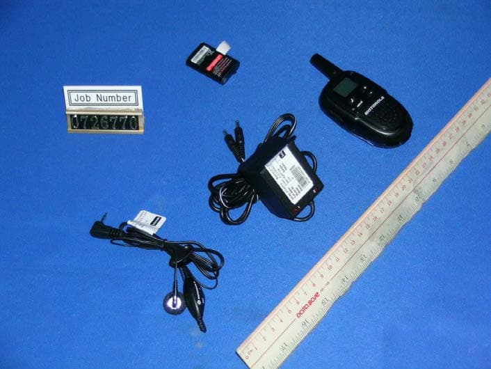
Click to zoom
Application Details
- Equipment Class
- FRF - Part 95 Family Radio Face Held Transmitter
- Date of Grant
- Jan 23, 2008
- Application Purpose
- Original Equipment
- Date of Application
- Jan 23, 2008
- Equipment Note
- Two Way Radio with GMRS and FRS
- Frequency Range
- 467.56250000 - 467.71250000
- Company
- Giant Electronics Ltd
- Country
- Hong Kong
Documents & Files
Document Text
Text extracted from the exhibit documents filed with the FCC. Open a document above to read the original.
Users Manual
Two-WayRadio User’s Guide F V30 0 Seri es Sa fety and Gen er al Information FC C LicensingInform at io n C on tro l Buttons KEM-PK14190-65 Im po rt ant Info rm ati on on Safe and Eff icient Operation ReadThisInformationBeforeUsingYourRadio. The inform ation providedin this doc umentsupersedesthe general saf et y informationin user gui des publi shed pr ior to December1, 2002 . Tran sm it and Recei ve Procedure Your tw o- way radio cont ains a transmitter and a receiver.To contr ol your exposureand ensurecompliance wit h the gener al populati on/ uncontrolled environmentex posurelimits,alway s adher e to the follow ing procedure: • Transmit no more than 50% of the tim e. • To recei ve calls, releasethe PTT but ton. • To tr ansmit(talk ), pressthe Push to Talk (PTT) butt on. Trans mi tting 50% of the ti me, or less, is importantbecause the radio gener ates meas urabl e RF energyexposureonly whentr ansmitting (in ter ms of measuring standardscompl iance). Ex po sur e to Rad io FrequencyEnerg y Your Motorolatwo-w ay radi o com pli es with the fol lowi ng RF energyexposurestandards and guidelines: • Uni te d States Fe deral com muni cati ons Commission, Code of Feder al Regul ations;47CF R par t 2 sub-part J • Am er ica n Nat ional St andardsIns ti tu te (ANSI)/Institute of Elec trica l and Elec tr on ic Engi nee rs (IEE E) C95. 1-1992 • Instit ute of Electricaland Electronics Engineers (IEEE)C95.1- 199 9 Editi on • Int ernati onal Comm issionon Non- IonizingRadiationPr otection (IC NIRP) 199 8 Gett in g St art ed DisplayScreenGuide Insta lling the Batte rie s Each radi o us es 1 Ni MH rechargeable batterypack or 3 AAA al kal ine batteries and beepswhen the batteries ar e low. Insta lling NiMH Recha rg eable Ba tte ry Pa ck (Optional Acce ssory ) 1. Turn the radi o off. 2. Wi th the back of the radio faci ng you, us e the bel t cl ip or a coi n to wedge the batterycoveropen. 3. Rem ove the batterypack from the cl ear pl as ti c bag (Do not disass em bl e or unw rap the batterypack). 4. Inser t the NiMH batterypack with the di agramfaci ng you. 5. Reposi ti on the batter y coverand pres s dow n to secure. Insta lling the Thre eAAAAlka line Batte rie s 1. Turn the radi o off. 2. Wi th the back of the radio faci ng you, us e the bel t cl ip or a coi n to wedge the batterycoveropen. 3. Inser t the thr ee AAA al kal ine batter ies with + and - polar ity as show n insi de. 4. Reposi ti on the batter y coverand pres s dow n to secure. Talkingand Listening To com muni cate, al l radi os in your gr oup mus t be set to the same channeland Inter fer ence El iminator Code. 1. To tal k, pr es s and hol d . 2. When you ar e fi nis hed tal king, rel eas e . For max imum cl ar ity, hol d the radi o tw o to thr ee inchesaway from your mouth and speak di rectl y into the micr ophone.Do not coverthe micr ophonewhi le tal king. Ta lk Rang e Yo ur radi o is des igned to max imize per for manceand improve trans mission range.Do not us e the radi os cl os er than five feet apart. Push to Talk Tim eout Tim er To pr ev ent acci dentaltr ans mi ss ions and sav e batterylife, the radio emits a conti nuouswar ni ng tone and stops tr ansmittingif you press for 60 conti nuousseconds. N otes : • The light wi ll remai n red after the batter y pack is fully charged. • When mov ing betw een hot and col d tem per atures,do not chargethe batter y unti l the batter y temperatur e accl imat es (usuallyabout20 minutes ). • For opti mal batter y life, unpl ug the char ging adapterwithin16 hours. Do not stor e the radi o whil e connectedto the charger. • When you r rad io is plug ged int o the AC pow er adapter, your radio will aut omat ical ly po we r of f. L ow Batte ry Ale rt In addi tion to your batter y meter show ing how muchbatterypoweryou have, your radi o will beep to aler t you to the fac t that your batteries are low. Attachingand Removing the Belt Clip 1. Attachbel t cl ip to pock et or bel t str ap. 2. Al ign the bel t cli p pos t with the hol e in the ba ck of the radio. 3. Gentl y pus h unti l the cl ip cli cks in pl ace. To Rem ov e 1. Pus h downon the rel eas e tab at the top of th e belt clip to release the catch. 2. Pull the belt cl ip aw ay fr om the back of the radio. TurningYour Radio On and Off To tur n on,pr es s and holdMENUunti l a channelnumberappears and the radi o beeps .To tur n off,pr es s and hol dMENUuntil the radio beepsand the dis play goes blank . Setting the Volum e Pr es s +to incr eas e or–to decr eas e the volume.The volumelevel flas hes and VOLdi spl ay s. Menu Options S electingthe Channel Your radio has 22 channels.The channelis the frequencyyour radio u ses to transmit. 1 . Brieflypressand releaseMENU. The channelnumberflashes. 2 . Press +o r –t o selecta channel. 3 . Pressto confirmorMENUto continueset up. For Mo re Info rm at io n Fo r furtherinformati on, you may cal l Moto rola at 1-80 0-6 38- 5119 (U.S. and Can ada), or e-m ail us at gi anti ntl @callcenter.comor visit us on the In terne t at www .mo torol a.com. S ettingand TransmittingCall Tones Your radio can transmitdifferentcall tonesto other radiosin your group so you can alert them that you want to talk. You have 10 call tonesfrom which to choose. To set a call tone: 1. With the radio on, short pressMENUuntil theappears.The currentcall tone settingflashes. 2 . Press +o r –t o changeand hear the call tone. 3 . Pressto set the new call tone orMENUto continueset up. To transmityour call tone to other radiosset to the same channelas your radio,press. Note:Settingthe call to 0 disablesthe call tone feature. KeypadTones You may enableor disablethe speakerkey tones.You will hear the key tone each time a buttonis pushed. 1. PressMENUuntilappears.The currentsettingOn/Offwill flash. 2. Presseither +or–to turn On or Off. 3. Pressto confirmorMENUto continueset up. Note:Whenthe Key Tone Featureis off, the followingare not disabled: • Transmittimeoutalert tone; • Power-downalert tone; • Low batteryalert tone; or • The transmittedTCT tone. Tr…
Text truncated - open the document above for the full version.
Cover Letter(s)
LETER OF AGENCY “I, am officer of Giant Electronics Ltd. do hereby authorize Intertek Testing Services(Mr. Ken Sit/Mr. Tommy Leung) to act on our behalf in front of the Federal Communications Commission with Respect to all matters relating to certification of equipment under part 15 and Part 95 of the FCC Rules until further notice.” I further certify that no party (as defined in 1.2002(b) of CFR 47, 1992) to this application, including myself, is subject to a denial of federal benefits, that includes FCC benefits, that includes FCC benefits, pursuant to Section 5301 of the Anti-Drug Abuse Act of 1988, 21 U.S.C., 853(a). EQUIPMENT: 1) 462MHz Two Way Radio w/GMRS&FRS (10 Call tone, 22 RF Channel Scan, ) FV300 Dated this 20th day of November 2007 By YK Ling Signature Printed Title: Electronic Engineer The content of this document is Giant Electronics Ltd.'s intellectual property and is the property of Giant. It is to be treated as strictly confidential and is not to be disclosed, reproduced, or used except as authorized in writing by Giant Electronics Ltd. In connection with the manufacture, maintenance and use of the Giant equipment to which it pertains. Copyright @Giant Electronics Ltd. All rights reserved. Letter of Agency
Cover Letter(s)
Re: FCC ID: K7GFV300 Pursuant to 47 CFR 0.459, Giant Electronics Ltd. request confidential protection of the following documents submitted electronically in furtherance of the above-reference application as containing propriety information listed below: ■ Schematic ■ Block Diagram ■ Operational Description ■ Tune Up Procedures ■ Detailed Operatonal/Functional Description This information represents intellectual property of Giant Electronics Ltd. and it is subject to competition. This information should not be made routinely available for public inspection, and Giant Electronics Ltd. reserves the right to discern which parties can obtain access to this information. Dated this 20th day of November 2007 By : YK Ling . Signature Printed Title : Electronic Engineer The content of this document is Giant Electronics Ltd.'s intellectual property and is the property of Giant. It is to be treated as strictly confidential and is not to be disclosed, reproduced, or used except as authorized in writing by Giant Electronics Ltd. In connection with the manufacture, maintenance and use of the Giant equipment to which it pertains. Copyright @Giant Electronics Ltd. All rights reserved. Confidentiality Request Letter
External Photos
INTERTEK TESTING SERVICES External Photos FCC ID: K7GFV300 external photos - 1 of 1 External Photo - Front External Photo - Rear
Internal Photos
INTERTEK TESTING SERVICES Internal photos FCC ID: K7GFV300 internal photos - 1 of 3 Internal Photo - 1 Internal Photo - 2 INTERTEK TESTING SERVICES Internal photos FCC ID: K7GFV300 internal photos - 2 of 3 Internal Photo - 3 Internal Photo - 4 INTERTEK TESTING SERVICES Internal photos FCC ID: K7GFV300 internal photos - 3 of 3 Internal Photo - 5
Test Report
- The evaluation data of the report will be kept for 3 years from the date of issuance. - This report is for the exclusive use of Intertek's Client and is provided pursuant to the agreement between Intertek and its Client. Intertek's responsibility and liability are limited to the terms and conditions of the agreement. Intertek assumes no liability to any party, other than to the Client in accordance with the agreement, for any loss, expense or damage occasioned by the use of this report. Only the Client is authorized to permit copying or distribution of this report and then only in its entirety. Any use of the Intertek name or one of its marks for the sale or advertisement of the tested material, product or service must first be approved in writing by Intertek. The observations and test results in this report are relevant only to the sample tested. This report by itself does not imply that the material, product, or service is or has ever been under an Intertek certification program. Intertek Testing Services Hong Kong Ltd. 2/F., Garment Centre, 576 Castle Peak Road, Kowloon, Hong Kong. Tel: (852) 2173 8888 Fax: (852) 2785 5487 Website: www.hk.intertek-etlsemko.com Giant Electronics Ltd. Application For Certification Two Way Radio with GMRS and FRS (FCC ID: K7GFV300) 07267701 TL/ ac December 28, 2007 INTERTEK TESTING SERVICES FCC ID: K7GFV300 i SUMMARY OF CONTENTS LIST OF EXHIBITS EXHIBIT 1: General Description EXHIBIT 2: System Test Configuration EXHIBIT 3: RF Power Output EXHIBIT 4: Modulation Characteristics EXHIBIT 5: Occupied Bandwidth EXHIBIT 6: Spurious Emission EXHIBIT 7: Frequency Stability EXHIBIT 8: Technical Specifications EXHIBIT 9: Product Labelling EXHIBIT 10: Photographs EXHIBIT 11: Instruction Manual EXHIBIT 12: Tune Up Procedure EXHIBIT 13: Part List EXHIBIT 14: Input Current EXHIBIT 15: RF Exposure Info EXHIBIT 16: Letter of Agency EXHIBIT 17: Confidentiality Request INTERTEK TESTING SERVICES FCC ID: K7GFV300 ii MEASUREMENT/TECHNICAL REPORT Application : Giant Electronics Ltd. Trade Name/Model No : Motorola FV300 Date : December 28, 2007 This report concerns (check one:)Original Grant X Class II Change Equipment Type: FRF – Part 95 Family Radio Face Held Transmitter Deferred grant requested per 47 CFR 0.457(d)(1)(ii)? Yes No X If yes, defer until: date Company Name agrees to notify the Commission by: date of the intended date of announcement of the product so that the grant can be issued on that date. Report prepared by: Leung Wai Leung, Tommy Intertek Testing Services Hong Kong Ltd. 2/F., Garment Centre, 576 Castle Peak Road, Kowloon, Hong Kong. Phone: 852-2173-8538 Fax: 852-2741-1693 INTERTEK TESTING SERVICES FCC ID: K7GFV300 iii Table of Contents 1.0 General Description............................................................................................................... 2 1.1 Product Description .............................................................................................................. 2 1.2 Related Submittal(s) Grants .................................................................................................. 3 1.3 Test Methodology ................................................................................................................. 3 1.4 Test Facility.......................................................................................................................... 3 2.0 System Test Configuration.................................................................................................... 5 2.1 Justification........................................................................................................................... 5 2.2 EUT Exercising Software ...................................................................................................... 6 2.3 Special Accessories.............................................................................................................. 6 2.4 Measurement Uncertainty .....................................................................................................6 2.5 Equipment Modification......................................................................................................... 6 3.0 RF Power Output (Section 95.639(d)).................................................................................. 8 4.0 Modulation Characteristics (Section 95.637(a)).................................................................. 12 4.1 Modulation Frequency Response ...................................................................................... 13 4.2 Modulation Limiting Characteristics ................................................................................... 15 4.3 Audio Low Pass Filter Response....................................................................................... 17 5.0 Occupied Bandwidth (Section 95.633(c))......................................................................... 19 6.0 Spurious Emission (Section 95.635(b)).............................................................................. 21 6.1 Field Strength of Spurious Radiation ................................................................................. 22 7.0 Frequency Stability (Section 95.627).................................................................................. 28 7.1 Frequency Tolerance......................................................................................................... 29 7.2 Temperature Extreme Condition........................................................................................ 31 7.3 Voltage Extreme Condition ................................................................................................ 34 8.0 Technical Specifications..................................................................................................... 37 9.0 Product Labelling................................................................................................................ 41 10.0 Equipment Ph…
Text truncated - open the document above for the full version.
Test Report
INTERTEK TESTING SERVICES Occupied Bandwidth Plots FCC ID: K7GFV300 bw - 1 of 1 Plot CH4 Plot CH11
Test Report
INTERTEK TESTING SERVICES A udio Low Pass Filter Response -70.0-60.0-50.0-40.0-30.0-20.0-10.0 0.0 10.0 1 10 100 Frequency (kHz) dB relative to 1 kHz LPF ResponseTIA/EIA-603B Audio Input Strength = 300 mVrms FCC ID: K7GFV300 lpf - 1 of 1 60 log (F/3)
Test Report
INTERTEK TESTING SERVICES Modulation Frequency Response 0.0000.5001.0001.5002.0002.500 100 600 1100 1600 2100 2600 3100 3600 4100 4600 Modulation Frequency (Hz) Frequency Deviation (kHz) FCC ID: K7GFV300 mfr - 1 of 2 INTERTEK TESTING SERVICES Modulation Frequency Response 0.000.501.001.502.002.503.003.504.004.505.005.506.00 100 600 1100 1600 2100 2600 3100 3600 4100 4600 Modulation Frequency (Hz) Modulation Index (%) FCC ID: K7GFV300 mfr - 2 of 2
Test Report
INTERTEK TESTING SERVICES Modulation Limiting Characteristic 0.0000.5001.0001.5002.0002.500 47 57 67 77 87 97 107 117 127 137 Modulation Input (dBSPL) Frequency Deviation (kHz) 500Hz1000Hz2500Hz3125Hz FCC ID: K7GFV300 mlc - 1 of 1
Test Report
INTERTEK TESTING SERVICES Spurious Emission Plots FCC ID:K7GFV300 spurious - 1 of 1 Plot CH4 Plot CH11
Test Setup Photos
INTERTEK TESTING SERVICES The Worst Case Configuration Photographs FCC ID: K7GFV300 config photos (radiated emission) - 1 of 1 Radiated Emission Front View Rear View
Contact Information
Applicant
Yumin Zou(A. Manager)
Technical Contact
Intertek Testing Services Hong Kong Ltd.Tommy Leung
[email protected](852)2173-8538
Flat D, 5/F., Garment Centre · Kowloon · China
Technical Specifications
| # | Rule Parts | Frequency Range | Power Output | Emission | Tolerance |
|---|---|---|---|---|---|
| 2 | 95B | 467.5625 MHz - 467.7125 MHz | 120.00 mW | 5K64F3E | 2.35 ppm |
Other Applications from Giant Electronics Ltd

K7GMDBJJPR
Jun 24, 2012Two Way Radio - FRS
Equipment Class
FRF - Part 95 Family Radio Face Held Transmitter
K7GMTCEJ
Apr 26, 2012Two Way Radio with GMRS and FRS
Equipment Class
CXX - Communications Rcvr for use w/ licensed Tx and CBs
K7GMDBJJ
Mar 01, 2012Two Way Radio with GMRS and FRS
Equipment Class
FRF - Part 95 Family Radio Face Held Transmitter
K7GMSFGJ
Mar 10, 2011Two Way Radio with Weather Band
Equipment Class
CXX - Communications Rcvr for use w/ licensed Tx and CBs
K7GT2007
Apr 08, 2010Two Way Radio with GMRS and FRS
Equipment Class
FRF - Part 95 Family Radio Face Held Transmitter