K7GR1010Two Way Radio with FRS and GMRS
Giant Electronics Ltd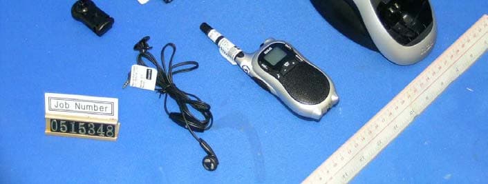
Click to zoom
Application Details
- Equipment Class
- FRF - Part 95 Family Radio Face Held Transmitter
- Date of Grant
- Nov 29, 2005
- Application Purpose
- Original Equipment
- Date of Application
- Nov 29, 2005
- Equipment Note
- Two Way Radio with FRS and GMRS
- Frequency Range
- 467.56250000 - 467.71250000
- Company
- Giant Electronics Ltd
- Country
- Hong Kong
Documents & Files
Document Text
Text extracted from the exhibit documents filed with the FCC. Open a document above to read the original.
Users Manual
(29-09) R1010 IB 1_0B 050928.doc (29-09) R1010 IB 1_0B 050928.doc SAFETY AND GENERAL INFORMATION Important Information for Safe and Efficient Operation Please read this information before using your radio. Safety and General 1. Do not transmit more than 50% of time. It is important as the radio generates measurable RF energy exposure only when transmitting. 2. Do not open the radio. Any unauthorized modification may violate FCC rules and invalidate the guarantee. 3. Radio frequency signals transmitted may cause interference to hearing aids. 4. Turn off the radio when near medical equipment. 5. This product should not be used by people with pacemakers. 6. Do not use the radio when driving a vehicle or operating machinery. 7. Do not use the radio when on board aircraft. 8. Do not hold the antenna when transmitting. 9. Do not use the radio when the antenna has damaged. 10. Turn off the radio and remove the batteries if you are not going to use it for a long time. 11. Do not attempt to charge alkaline batteries. 12. Only use the power adapter charger supplied. Using an unauthorized charger will invalidate the guarantee and may damage the product. 13. Only use the approved headsets with the radio. (29-09) R1010 IB 1_0B 050928.doc Two-way Radio Operation The device was tested for typical body-worn operations using the supplied belt-clip. To maintain compliance with FCC RF exposure requirements, body-worn operations are restricted to the supplied belt-clip. For hand-held operation, the radio should be held at least 1 inch (2.5cm) from the user’s face. The use of accessories that do not satisfy these requirements may not comply with FCC RF exposure requirements and should be avoided. For more information about RF exposure, please visit the FCC web site at www.fcc.gov. Approved Accessories For a list of approved RCA accessories, visit our Web site at www.RCA.com. OPERATIONAL CAUTIONS 1. Never dispose of batteries in a fire. There is a serious risk of explosion and /or the release of highly toxic chemicals. 2. Do not expose your product to direct sunlight, extreme cold or place it near heating appliances. 3. Do not submerge any part of your product in water and do not use it in damp, humid or wet conditions. 4. Do not expose your product to fire, explosive or other hazardous conditions. For example, at petrol stations or areas where explosive products are used. (29-09) R1010 IB 1_0B 050928.doc FCC LICENSING INFORMATION This two-way radio operates on GMRS (General Mobile Radio Service) frequencies which require an FCC (Federal Communications Commission) license. A user must be licensed prior to operating on any GMRS channels. Serious penalties could result for unlicensed use of GMRS channels, in violation of FCC rules, as stipulated in the Communications Act’s Sections 501 and 502 (amended). Licensed users will be issued a call sign by the FCC, which should be used for station identification when operating this radio. GMRS users should also cooperate by engaging in permissible transmissions only, avoiding channel interference with other GMRS users, and being prudent with the length of their transmission time. Application for a GMRS system license can be made on FCC Form 605. You can call the FCC Forms Hotline 1-800-418-FORM (3676). If You Have Questions about the FCC License: Call the FCC 1-888-CALL-FCC (225-5322). You may also visit the FCC’s Web site at http://www.fcc.gov or http://wireless.fcc.gov/services/personal/generalmobile/ concerning GMRS. Note: Use of this radio outside the country where it was intended to be distributed is subject to government regulations and may be prohibited. (29-09) R1010 IB 1_0B 050928.doc Warning: Any adjustment to this equipment is recommended to be performed by or under the immediate supervision and responsibility of a person certified as technically qualified to perform transmitter maintenance and repair duties in the private land mobile services and fixed services by an organization or committee representative of users of those services. Warning: Replacement of any transmitter component (crystal, semiconductor, etc.) for this equipment could result in violation of FCC rules. Use only the supplied antenna. Unauthorized antennas, modifications, or attachments could damage the transmitter and may violate FCC regulations. (29-09) R1010 IB 1_0B 050928.doc FCC STATEMENTS: This device complies with Part 15 of the FCC Rules. Operation is subject to the following two conditions: (1) this device may not cause harmful interference, and (2) this device must accept any interference received, including interference that may cause undesired operation. NOTE: This equipment has been tested and found to comply with the limits for a Class B digital device, pursuant to Part 15 of the FCC Rules. These limits are designed to provide reasonable protection against harmful interference in a residential installation. This equipment generates, uses and can radiate radio frequency energy and, if not installed and used in accordance with the instructions, may cause harmful interference to radio communications. However, there is no guarantee that interference will not occur in a particular installation. If this equipment does cause harmful interference to radio or television reception, which can be determined by turning the equipment off and on, the user is encouraged to try to correct the interference by one or more of the following measures: Reorient or relocate the receiving antenna. Increase the separation between the equipment and receiver. Connect the equipment into an outlet on a circuit different from that to which the receiver is connected. Consult the dealer or an experienced radio/TV technician for help. CONTROL BUTTONS AND DISPLAY ICONS– MODEL R1010 SERIES 1. Antenna 2. LED - The red light stays on when transmitting 3. ‘VOL-’Volume decrease 4. Start transmitting and transmits with low power on all channels 5. Transmit your call tone to other radios set to the same channel…
Text truncated - open the document above for the full version.
Cover Letter(s)
The content of this document is Giant Electronics Ltd.'s intellectual property and is the property of Giant. It is to be treated as strictly confidential and is not to be disclosed, reproduced, or used except as authorized in writing by Giant Electronics Ltd. In connection with the manufacture, maintenance and use of the Giant equipment to which it pertains. Copyright @Giant Electronics Ltd. All rights reserved. Re: FCC ID: K7GR1010 Pursuant to 47 CFR 0.459, Giant Electronics Ltd. request confidential protection of the following documents submitted electronically in furtherance of the above-reference application as containing propriety information listed below: ■ Schematic ■ Block Diagram ■ Operational Description This information represents intellectual property of Giant Electronics Ltd. and it is subject to competition. This information should not be made routinely available for public inspection, and Giant Electronics Ltd. reserves the right to discern which parties can obtain access to this information. Dated this 19 th day of July 2005 By: YK Ling . Signature Printed Title : Electronic Engineer Confidentiality Request Letter
Cover Letter(s)
From: Kenneth CC Lam ES-HKG Sent: Monday, November 21, 2005 1:20 AM To: Roland Gubisch ES-Box Cc: Tommy Leung ES-HKG Subject: RE: Review of TCB application Giant FCC ID: K7GR1010 Dear Roland Thanks for your questions! After we have consulted with ITS-Taiwan SAR Lab, we would like to answer your questions as follows: SAR REPORT (1) Probe linearity and dynamic range specifications cannot be found. Please indicate where this information is located, or provide. Ans 1: Pls refer to page 66 of attached revised SAR report for the probe linearity and dynamic range specifications (2) FCC requirement for probe spherical isotropy is < 0.5 dB. Probe used has a spherical isotropy of 0.56 dB. Please explain. (3) Measurement uncertainty calculations are based on probe spherical isotropy of 0.45 dB; actual specification is 0.56 dB; please explain. Ans 2 and 3: pls refer to page 68, The correct of spherical isotropy is 0.38. This reading 0.56dB is a typing error that is revised in the attached report. If you have any query, please feel free to contact me. Best Regards, Kenneth C.C. Lam Senior Lead Engineer Intertek ETL SEMKO Division Phone Number: (852) 2173 8474 Fax Number: (852) 2741 1693 [email protected] www.hongkong.etlsemko.com -----Original Message----- From: Tommy Leung ES-HKG Sent: Saturday, October 29, 2005 11:41 AM To: Kenneth CC Lam ES-HKG Subject: FW: Review of TCB application Giant FCC ID: K7GR1010 Dear Kenneth, Please follow. If you need other information, please feel free to contact me. Thanks and best regards, Tommy Leung Assistant Manager Intertek Hong Kong ETL SEMKO Division Pager Number: (852) 7302 3113 Phone Number: (852) 2173 8538 Fax Number: (852) 2741 1693 [email protected] www.hongkong.etlsemko.com Please visit our website for latest market and standards news: <http://www.hongkong.intertek-etlsemko.com/en/news.asp> -----Original Message----- From: Roland Gubisch ES-Box Sent: Saturday, October 29, 2005 05:04 AM To: Kathy Chan ES-HKG Cc: Tommy Leung ES-HKG; Terre Wolak ES-Atl Subject: RE: Review of TCB application Giant FCC ID: K7GR1010 Dear Kathy, Review of this application is complete and the following points are noted: ADMINISTRATIVE - none EMC REPORT - none SAR REPORT (1) Probe linearity and dynamic range specifications cannot be found. Please indicate where this information is located, or provide. (2) FCC requirement for probe spherical isotropy is < 0.5 dB. Probe used has a spherical isotropy of 0.56 dB. Please explain. (3) Measurement uncertainty calculations are based on probe spherical isotropy of 0.45 dB; actual specification is 0.56 dB; please explain. Certification can proceed when these points have been addressed. Thank you, Roland
External Photos
INTERTEK TESTING SERVICES External Photos FCC ID: K7GR1010 external photos - 1 of 1 External Photo - Front External Photo - Rear
Internal Photos
INTERTEK TESTING SERVICES Internal photos FCC ID: K7GR1010 internal photos - 1 of 3 Internal Photo - 1 Internal Photo - 2 INTERTEK TESTING SERVICES Internal photos FCC ID: K7GR1010 internal photos - 2 of 3 Internal Photo - 3 Internal Photo - 4 INTERTEK TESTING SERVICES Internal photos FCC ID: K7GR1010 internal photos - 3 of 3 Internal Photo - 5 Internal Photo -6
Parts List/Tune Up Info
Giant Electronics Ltd. Level Item Description Qty U/M Schema ----- ---- ----------- - --- - --- ------ Parent R1010ARCUSSVA4 FRS RADIO USA RCA SILVER W/CHARGER EA1 CH100ARCUSSV09 FRS CHARGER FOR R1010 AMERICA(RCA) SILVER 1 EA0.2 CH100BA1USSVXX BASE ASSY AMERICA(RCA) SILVER 1 EA..3 CH100BC4USSVXX BASE CASING AMERICA (RCA) SILVER 1 EA...4 CH100BCXXX BASE CASING COMMON 1 EA....5 KEM-M19501 R1010 CHARGER CONTACT PLATE 4 EA....5 KEM-OT19501 RUBBER CAP 4 EA....5 KEM-OT8361 RUBBER FOOT 4 EA....5 KEM-TS2305X4B TAPTITE SCREW X/HD T2.3X5 4 EA....5 KEM-TS2310X4B TAPTITE SCREW X/HD T2.3X10 4 EA...4 CH100BC4SV BASE CASING AMERICA SILVER 1 EA....5 KEM-P19501 R1010 CHARGER FRONT HOUSING 1 EA....5 KEM-P19502 CHARGER BACK HOUSING 1 EA....5 KEM-P19503 CHARGER BACK COVER 1 EA..3 CH100B1 CHARGER PCB 700mA BATTERY FOR R1010(ALL) 1 EA...4 CH100B1XXX CHANGER PCB MAIN PART 1 EA....5 KEJ-225 JACK DC-290-002-00 SUN RISE 2 EA J1,J2....5 KEM-M10896 CONTACT PCB 4 EA B1,B2,B3,B4....5 KEPC-961-A PCB CHARGE 79.1X79.1X1.6mm SS 94V0 1 EA....5 KER-MX180EBB RES.METAL-OXIDE 1W 5% S 18 OHM 2 EA R4,R11 R1010BAXRCSVXX BASE UNIT RCA SILVER 2 EA0.2 R1010BCXRCSVXX BASE CASING RCA SILVER 1 EA..3 R1010BCXXX BASE CASING COMMON 1 EA...4 KEM-M12755-01 BATTERY CONTACT COMPOSITE 2 EA...4 KEM-M17501 SPEAKER STEEL NET 1 EA...4 KEM-M17502 ANTENNA WIRE 1 EA...4 KEM-M17503 LCD BRACKET 1 EA...4 KEM-M17504-02 SHIELD CAN COVER 1 EA...4 KEM-M17505 CHARGER PLATE 2 EA...4 KEM-M17601 POSITIVE NEGATIVE PLATE 1 EA...4 KEM-M17602 POSITIVE PLATE 1 EA...4 KEM-M17603 NEGATIVE PLATE 1 EA...4 KEM-OT12957 PVC COVER 1 EA...4 KEM-OT17501 KEYPAD A 1 EA...4 KEM-OT17502 KEYPAD B 1 EA...4 KEM-OT17503 PTT BUTTON 1 EA...4 KEM-OT17504 METAL DOME 1 EA...4 KEM-OT17505 DIFFUSE PAPER 1 EA...4 KEM-OT17506 REFLECTED PAPER A 1 EA...4 KEM-OT17507 REFLECTED PAPER B 1 EA...4 KEM-OT17508-01 REFLECTED PAPER C1 2 EA...4 KEM-OT17508-02 REFLECTED PAPER C2 2 EA...4 KEM-OT17509 NYLON NET 1 EA...4 KEM-OT17510 TAPE FOR PTT METAL DOME 1 EA...4 KEM-OT17607 LENS PROTECT FILM 1 EA...4 KEM-OT5963 MIC CUSHION COVER 1 EA...4 KEM-OT7186 SPEAKER CUSHION 1 EA R1010.xls..R1010 Print:2005-8-23 Page 1 of 7 Giant Electronics Ltd. Level Item Description Qty U/M Schema ----- ---- ----------- - --- - --- ------ ...4 KEM-OT7357 SPEAKER SPONGE 1 EA...4 KEM-OT9753 PTT METAL DOME 1 EA...4 KEM-OT9763 CUSHION IN ANTENNA 1 EA...4 KEM-P11558 BELT CLIP COVER BLACK 1 EA...4 KEM-P17501-01 FRONT HOUSING (SILVER) 1 EA...4 KEM-P17502 REAR HOUSING BLACK 1 EA...4 KEM-P17503 BACK LIGHT BOARD 1 EA...4 KEM-P17504-01 LCD LENS W/PRINTING 1 EA....5 KEM-P17504 LCD LENS 1 EA....5 KEM-P17504-01Z PRINTING FOR LCD LENS 1 EA...4 KEM-P17505 LED LENS 1 EA...4 KEM-P17506 ANTENNA CAP 1 EA...4 KEM-P17507 ANTENNA INSERT 1 EA...4 KEM-P17508 BATTERY DOOR 1 EA...4 KEM-P17509 DUST CAP 1 EA...4 KEM-P17510-01 FACE PLATE(SILVER) 1 EA...4 KEM-TS2308X4B TAPTITE SCREW X/HD T2.3X8 4 EA0.2 R1010B1XUSXXXX BASE RF & MAIN PCB US 1 EA..3 R1010B1 BASE RF & MAIN PCB (ALL) 1 EA...4 R1010B1XXXU BASE RF & MAIN UNIQUE PART 1 EA....5 R1010B1SU BASE RF & MAIN SMT UNIQUE PART 1 EA.....6 R1010B1SBU BASE RF & MAIN SMT BOTTOM UNIQUE PART 1 EA.....6 R1010B1STU BASE RF & MAIN SMT TOP UNIQUE PART 1 EA...4 R11CCBCXXXC BASE CASING COMMON PARTS 1 EA....5 KEJW-SA28BK STRAND WIRE UL1007 #28 BLACK 0.04 M SP-....5 KEJW-SA28RD STRAND WIRE UL1007 #28 RED 0.04 M SP+....5 KESP-122-3 SPERKER 32 OHM 0.5W ASAHI-EP LEAD-FREE 1 EA SPK101....5 KESP-172 MIC DB C9745 DD422LF-Q050 42dB 1 EA MIC101....5 KESP-172-B MIC KISS-JIA ECM KSJ9745P 0 EA MIC101...4 R11CCB1XXXC BASE RF & MAIN COMMON PART 1 EA....5 KEC-E107CRMKA CAP. ELECT. 6.3V M% 100UF 2 EA C5,C111....5 KEC-E227DRMKA CAP. ELECT. 10V M% 220UF 1 EA C108....5 KECF-0126-C SAW FILTER F-11 465MHZ FTF465B FRONTER 1 EA BPF501....5 KECF-0159-B FILTER 450KHZ LTM450HTW FRONTER 1 EA BPF503....5 KECF-0163-A2 CRYSTAL FILTER FT21M07A 21.4M FRONTER 1 EA BPF502....5 KED-LC101 LCD 24X21.5X2.0mm SHANTOU 1 EA LCD101....5 KED-L104O LED LTIFA3-A2-UBC1-S9 ORANGE 1 EA D1....5 KEJ-225 JACK DC-290-002-00 SUN RISE 1 EA J1....5 KEJ-465-A JACK EARPHONE/MIC ST-155 KWAN TAT 1 EA J101....5 KEJW-FC182 HEAT SEAL H=12MM P=1.4MM L=18MM 12PINS 1 EA FOR PCB-LCD....5 KEOE-OT482 JTB 450KHZ CERAMIC DISCRIMINATOR 1 EA L517....5 KEX-C074-1 CERAMIC RESONATOR 4MHZ +/-0.2% 1 EA X101....5 R11CCB1SC BASE RF & MAIN PCB SMT COMMON PARTS 1 EA.....6 KEPC-958-A PCB FR4 91MMX46MMX1.2MM 1 EA PCB.....6 KEX-0412 CRYSTAL UNIT 1 EA X501.....6 KEX-0394-C CRYSTAL 0 EA X501.....6 KEX-0394-C1 CRYSTAL 20.95MHZ BLACK UM-1 CL=15PF 0 EA X501 R1010.xls..R1010 Print:2005-8-23 Page 2 of 7 Giant Electronics Ltd. Level Item Description Qty U/M Schema ----- ---- ----------- - --- - --- ------ .....6 KEX-0394-C3 CRYSTAL 20.95MHZ YELLOW UM-1 CL=15PF 0 EA X501.....6 KEX-0394-C4 CRYSTAL 20.95MHZ GREEN UM-1 CL=15PF 0 EA X501.....6 KEX-0412-2 CRYSTAL 20M95HZ B CL=15PF UM-1 CMT WHITE 0 EA X501.....6 KEX-0412-3 CRYSTAL 20M95HZ C CL=15PF UM-1 CMT YELLOW 0 EA X501.....6 KEX-0412-4 CRYSTAL 20M95HZ D CL=15PF UM-1 CMT GREEN 0 EA X501.....6 R11CCB1SBC BASE RF & MAIN PCB SMT BOTTOM COMMON PART 1 EA......7 KCC-101FJCOGEYG CAP CER CHIP 50V COG J 100PF 9 EA C109,C600,C106,C603,C608,C560,C552,C9,C11......7 KCC-101FJNPOMUG CAP.CER.CHIP 50V CH J% 100PF MURATA 0 EA C109,C600,C106,C603,C608,C560,C552,C9,C11......7 KCC-103BKBEYG CAP CER 0.01U 10% 10V X7R 0402 3 EA C551,C557,C510......7 KCC-103BKBMUG CAP. CER. CHIP 10V X7R K 0.01UF 0 EA C551,C557,C510......7 KCC-104DKBEYG CAP CER 16V X7R K 100NF 0402 5 EA C562,C563,C574,C558,C573......7 KCC-104BKBMUG CAP. CER. CHIP 10V X7R K 0.1UF 0 EA C562,C563,C574,C558,C573......7 KCC-105BZY5VPAB CAP CER CHIP 10V Y5V 1uF Z PANASONIC 1 2 EA C559,C528......7 KCC-105BRZFB CAP. CER. CHIP 10V Y5V Z% 1UF 0 EA C559,C528......7 KCC-105CZY5VMUG CAP CER CHIP 6.3V Y5V 1uF Z 0402 MURATA 0 EA C193,C604......7 KCC-105CZY5VPAG CAP CER CHIP 6.3V Y5V 1uF Z PANASONIC 0 2 EA C604,C193......7 KCC-106BZBPAM-1 CAP CER CHIP 10V Y5V 10uF Z PANASONIC M 2 EA C704,C561......7 KCC-106BRZFM-1 CAP. CER. CHIP 10V F Z% …
Text truncated - open the document above for the full version.
Parts List/Tune Up Info
GIANT ELECTRONICS LTD. Title: Alignment Procedure Revision No.: A Model: R1010 Date: JUNE 27, 2005 THE CONTENT OF THIS DOCUMENT IS GIANT ELCT.LTD. INTELLECTUAL PROPERTY AND IS THE PROPERTY OF GIANT, IT IS TO BE TREATED AS STRICTLY AND IS NOT BE DISCLOSED, REPRODUCED, OR USED EXCEPT AS AUTHORIZED IN WRITING BY GIANT ELECTRONIC LTD. IN CONNECTION WITH THE MANUFACTURE, MAINTENANCE AND USE OF THE GIANT EQUIPMENT WHICH IT PERTAINS. COPYRIGHT @GIANT ELECT. LTD, ALL RIGHTS RESERVED. _R1010 alignment.doc Page: 1 / 5 A. PCB LEVEL (Test Condition: under CH15, Supply=5.2Vdc) NO ITEM ALIGNMENT METHOD REMARK 1. LCD display (Should enter test mode) 1. Press and hold the ‘+’ key and ‘Menu’ key together. 2. Turn on the radio power until a good key chirp is heard, and the backlight is on for about 500ms, finally, the LCD should be display ‘ 1 CH ’. 3. Press ‘-’ key , then all LCD segments should be anticlockwise displayed. 4. Finally, all the LCD segments should be shown for about 500ms as follows: 218 88. . 2. Standby current 1. Set A-METER, and RX mode. 2. Check the standby current <50mA DC. 3. VCO 1. Set RX or TX mode 2. Check TP503 to provide 0.7~2.3V DC . 3. Adjust L509 to provide 2.2 ± 0.1VDC at TP503 if VCO level are more than 2.3VDC on CH14. 4. TX Power&TX current 1. Set TX mode CH15, Check the transmit to 0.63 W ERP, the talk on current <1000mA. 2. Set TX mode CH14, adjust VR503 to 0.12 W ERP, Check the talk on current <500mA. Test Voltage 6.0Vdc 5. TX Frequency 1. Set TX mode CH8; 2. Adjust VC501 to provide 467.5625MHz ± 50Hz. 6. CTCSS Tone Frequency 1. Set CH8/CODE1 and Tx mode. 2. Check CTCSS tone frequency to be within 66.8Hz to 67.2Hz. 7. TX Modulation & distortion 1. Set AF level at 50mv;1KHz,Adjust VR101 to provide Max TX deviation 2.1KHz to 2.3KHz. 2.Check input Mic level in 5~15 mV to provide normal deviation 1.5KHz. 3.Check the demodulation distortion <= 5%. 4.Audio Frequency Response. a) Input a 3.0mV 1KHz audio frequency to TP116 and press ‘PTT’ switch. b) Check the response compare to 1KHz tone. i) 500Hz : -12.5 dB to –6.5 dB. ii) 2.5KHz : +5.0 dB to +11 dB . ITEM1, 4 FILTER SET: I. HPF 50Hz II. LPF 15KHz ITEM2, 3 FILTER SET: I. HPF 300Hz II. LPF 3KHz 8. CTCSS Tone Dev. 1. Set CH8/CODE1、AF input level to off, check DEV to be 350Hz~ 650Hz. 2. Set CH8/CODE38、AF input level to off, check DEV to be 350Hz~ 650Hz. 3. Set CH8/CODE19 、 AF input level to off, check DEV to be 350Hz~ 650Hz. FILTER SET: 1. <20HZ~300HZ 2. 750μs De-emp ON 1. PK+ 2. FM DEV. AVG ON GIANT ELECTRONICS LTD. Title: Alignment Procedure Revision No.: A Model: R1010 Date: JUNE 27, 2005 THE CONTENT OF THIS DOCUMENT IS GIANT ELCT.LTD. INTELLECTUAL PROPERTY AND IS THE PROPERTY OF GIANT, IT IS TO BE TREATED AS STRICTLY AND IS NOT BE DISCLOSED, REPRODUCED, OR USED EXCEPT AS AUTHORIZED IN WRITING BY GIANT ELECTRONIC LTD. IN CONNECTION WITH THE MANUFACTURE, MAINTENANCE AND USE OF THE GIANT EQUIPMENT WHICH IT PERTAINS. COPYRIGHT @GIANT ELECT. LTD, ALL RIGHTS RESERVED. _R1010 alignment.doc Page: 2 / 5 A. PCB LEVEL (Test Condition: under CH15) NO ITEM ALIGNMENT METHOD REMARK 9. VOX Detector 1. Set VOX level at 1. 2. Set AF level at 12.5 +/- 1.5 mV,1KHz at TP116. 3. Unit start to transmit. 4. Set AF level at 10.5 +/- 1.5mV,1KHz at TP116. 5. Unit stop transmit. 6. Set VOX level at 2. 7. Set AF level at 8 +/-1.5mV,1KHz at TP116. 8. Unit start to transmit. 9. Set AF level at 7.0+/- 1.5mV,1KHz at TP116 . 10. Unit stop transmit. 11. Set VOX level at 3 12. Set AF level at 4.5 +/- 1mV,1KHz at TP116 . 13. Unit start to transmit. 14. Set AF level at 3.5+/- 1mV,1KHz at TP116. 15. Unit stop transmit. 10. IVOX Detector As same as item 11 11. Rx Audio test 1. Set RX mode CH7. 2. Set SG RF level to –50dBm with 1.5KHz deviation 1KHz modulation Signal. 3. Adjust the volume key to give a Max audio output at TP117. 4. Check Max audio output level >1450mV. 5. Check Rx current <150mA. 6. Check the 1KHz distortion <= 5%. 7. Set SG RF level to –118dBm with 1.5kHz deviation at 1KHz audio frequency. a). Check SINAD sensitivity <= -119dBm. @12dB SINAD at TP117 . 8. Audio frequency response. a) Set SG RF level to –50dBm with 1.5kHz deviation at 1KHz audio frequency. b) Adjust the volume key to give an output 700mV± 100mV at TP117. c) Vary the audio frequency from 300Hz to 3KHz. d) Check the RX response compare to 1KHz tone. i) 500Hz : -13 to –7.0 dB. ii) 2.5KHz : -15 to –9.0 dB 9. Maximum and Minimum Audio Output Power. a) Set SG RF level to –50dBm with 1.5kHz deviation at 1KHz audio frequency. b) Adjust the volume key to give a maximum output . c) Check the voltage at TP117 ≥1450mV. d) Set maximum audio output to 0dB, Adjust the volume keyto give a minimum output. e) Check the minimum voltage -20 to -12dB at TP117 GIANT ELECTRONICS LTD. Title: Alignment Procedure Revision No.: A Model: R1010 Date: JUNE 27, 2005 THE CONTENT OF THIS DOCUMENT IS GIANT ELCT.LTD. INTELLECTUAL PROPERTY AND IS THE PROPERTY OF GIANT, IT IS TO BE TREATED AS STRICTLY AND IS NOT BE DISCLOSED, REPRODUCED, OR USED EXCEPT AS AUTHORIZED IN WRITING BY GIANT ELECTRONIC LTD. IN CONNECTION WITH THE MANUFACTURE, MAINTENANCE AND USE OF THE GIANT EQUIPMENT WHICH IT PERTAINS. COPYRIGHT @GIANT ELECT. LTD, ALL RIGHTS RESERVED. _R1010 alignment.doc Page: 3 / 5 A. PCB LEVEL (Test Condition: under CH15) NO ITEM ALIGNMENT METHOD REMARK 12. Noise- Detector 1. Set SG to –120dBm with 1.5KHz deviation., 1KHz AF on CH7. 2. Press ”Mon” key and Adjust VR502 for transient state @ 10dB SINAD. 3. Check high state @8 to 12dB SINAD. 13. CTCSS Tone Detect 1. Set CH15/CODE1 and SG to –60dBm with 67Hz tone frequency, 400Hz deviation. 2. Check TP4, it have square-wave, and low for RF modulation off. 3. Repeat item 1 and 2 for code38 (250.3Hz). 4. Repeat item 1 ~ 3 for CH14. 14. Quiet Noise Detect 1. Set unit to quiet noise mode 2. Set CH15/CODE1and SG to –60dBm with 67Hz tone frequency, 400Hz deviation and 55 Hz audio frequency, 1K deviation. 3. 55 Hz tone Frequency appear on TP117. 15. Normal Batter level Detect 1. I…
Text truncated - open the document above for the full version.
RF Exposure Info
FCC ID. : K7GR1010 Report No.: EME-050967 Page 1 of 79 0597 ILAC MRA Specific Absorption Rate (SAR) Test Report for Giant Electronics Ltd. on the Two Way Radio With GMRS and FRS Model Number: R1010 Test Report: EME-050967 Issue date: Sep. 14, 2005 Total No of Pages Contained in this Report: 79 Tested by: Kevin Chen Reviewed by: Jerry Liu Review Date: Sep. 14, 2005 All services undertaken are subject to the following general policy: Reports are submitted for exclusive use of the client to whom they are addressed. Their significance is subject to the adequacy and representative character of the samples and to the comprehensiveness of the tests, examinations or surveys made. This report shall not be reproduced except in full, without written consent of Intertek Testing Services, Taiwan Ltd. FCC ID. : K7GR1010 Report No.: EME-050967 Page 2 of 79 Table of Contents 1.0 General information .................................................................................................... 3 1.1 Client Information....................................................................................................... 3 1.2 Equipment under test (EUT) ....................................................................................... 4 1.3 Test plan reference ...................................................................................................... 4 1.4 Test configuration ....................................................................................................... 5 1.4.1 Support equipment & EUT antenna position ....................................................... 5 1.4.2 Test Condition ...................................................................................................... 6 1.5 Modifications required for compliance....................................................................... 6 2.0 SAR Evaluation........................................................................................................... 7 2.1 SAR Limits .................................................................................................................7 2.2 Configuration Photographs ......................................................................................... 8 2.3 SAR measurement system ........................................................................................ 13 2.4 SAR measurement system validation ....................................................................... 14 2.4.1 System Validation result ..................................................................................... 15 2.4.2 System Performance Check result...................................................................... 17 2.5 Test Result................................................................................................................. 19 3.0 Test Equipment ......................................................................................................... 21 3.1 Equipment List .......................................................................................................... 21 3.2 Tissue Simulating Liquid .......................................................................................... 22 3.2.1 Body Tissue Simulating Liquid for evaluation test ............................................ 22 3.2.2 Head Tissue Simulating Liquid for System performance Check and evaluation test 22 3.2.3 Body Liquid results ............................................................................................ 23 3.2.4 Head Liquid results ............................................................................................ 24 3.3 E-Field Probe and 450 Balanced Dipole Antenna Calibration ................................. 25 4.0 Measurement Uncertainty ......................................................................................... 26 5.0 Warning Label Information - USA ........................................................................... 28 6.0 References .................................................................................................................29 7.0 Document History ..................................................................................................... 30 APPENDIX A - SAR Evaluation Data ........................................................................... 31 APPENDIX B - Photographs .......................................................................................... 48 APPENDIX C - E-Field Probe and 450MHz Balanced Dipole Antenna Calibration Data56 FCC ID. : K7GR1010 Report No.: EME-050967 Page 3 of 79 1.0 General information The Giant sample device, model # R1010 was evaluated in accordance with the requirements for compliance testing defined in FCC OET Bulletin 65, Supplement C (Edition 01-01). Testing was performed at the Intertek Testing Services facility in Hsinchu, Taiwan. The maximum output power declared by the Giant. The EUT was evaluated in a face-held configuration with the front of the radio placed parallel to the outer surface of the planar. A 2.5cm separation distance was maintained between the front side of the EUT and the outer surface of the planar phantom for the duration of the test. The EUT was tested in a body-worn configuration with the rear of the radio placed parallel to outer surface of the planar phantom. The attached plastic belt-clip was touching the planar phantom. The EUT was evaluated for body-worn SAR with the microphone accessory. For the evaluation, the dosimetric assessment system INDEXSAR SARA2 was used. The phantom employed was the box phantom of 6 mm thick in one wall. The total uncertainty for the evaluation of the spatial peak SAR values averaged over a cube of 1g tissue mass had been assessed for this system to be ±20.6%. The device was tested in unmodulated continuous transmit operation (Continuous Wave at 100% duty cycle) with the transmit key constantly depressed. For a push-to-talk device, the 50% duty cycle compensation reported…
Text truncated - open the document above for the full version.
Test Report
• The test results reported in this report shall refer only to the sample actually tested and shall not refer or be deemed a refer to bulk from which such a sample may be said to have been obtained. • This report shall not be reproduced except in full without prior authorization from Intertek Testing Services Hong Kong Limited • For Terms And Conditions of the services, it can be provided upon request. • The evaluation data of the report will be kept for 3 years from the date of issuance. Intertek Testing Services Hong Kong Ltd. 2/F., Garment Centre, 576 Castle Peak Road, Kowloon, Hong Kong. Tel: (852) 2173 8888 Fax: (852) 2371 0521 Website: www.hk.intertek-etlsemko.com Giant Electronics Limited Application For Certification Two Way Radio with GMRS and FRS (FCC ID: K7GR1010) 0515348 TL/ Ann Choy September 21, 2005 INTERTEK TESTING SERVICES FCC ID: K7GR1010 i SUMMARY OF CONTENTS LIST OF EXHIBITS EXHIBIT 1: General Description EXHIBIT 2 : System Test Configuration EXHIBIT 3: RF Power Output EXHIBIT 4: Modulation Characteristics EXHIBIT 5: Occupied Bandwidth EXHIBIT 6: Spurious Emission EXHIBIT 7: Frequency Stability EXHIBIT 8: Technical Specifications EXHIBIT 9: Product Labelling EXHIBIT 10: Photographs EXHIBIT 11: Instruction Manual EXHIBIT 12: Tune Up Procedure EXHIBIT 13: Part List EXHIBIT 14: Input Current EXHIBIT 15: RF Exposure Info EXHIBIT 16: Confidentiality Request INTERTEK TESTING SERVICES FCC ID: K7GR1010 ii MEASUREMENT/TECHNICAL REPORT Application : Giant Electronics Limited Trade Name/Model No : RCA/ R1010 Date : September 21, 2005 This report concerns (check one:)Original Grant X Class II Change Equipment T…
Text truncated - open the document above for the full version.
Contact Information
Applicant
Yumin Zou(A. Manager)
Technical Contact
Intertek Testing Services Hong Kong Ltd.Tommy Leung
[email protected]852-2173-8538
2/F., Garment Centre · Kowloon · Hong Kong
Non-Technical Contact
Intertek Testing Services Hong Kong Ltd.Tommy Leung
[email protected]852-2173-8538
Test Firm
Intertek Testing Services Hong KongBilly Chow
Technical Specifications
| # | Rule Parts | Frequency Range | Power Output | Emission | Tolerance |
|---|---|---|---|---|---|
| 2 | 95B | 467.5625 MHz - 467.7125 MHz | 120.00 mW | 5K80F3E | 1.52 ppm |
Other Applications from Giant Electronics Ltd

K7GMDBJJPR
Jun 24, 2012Two Way Radio - FRS
Equipment Class
FRF - Part 95 Family Radio Face Held Transmitter
K7GMTCEJ
Apr 26, 2012Two Way Radio with GMRS and FRS
Equipment Class
CXX - Communications Rcvr for use w/ licensed Tx and CBs
K7GMDBJJ
Mar 01, 2012Two Way Radio with GMRS and FRS
Equipment Class
FRF - Part 95 Family Radio Face Held Transmitter
K7GMSFGJ
Mar 10, 2011Two Way Radio with Weather Band
Equipment Class
CXX - Communications Rcvr for use w/ licensed Tx and CBs
K7GT2007
Apr 08, 2010Two Way Radio with GMRS and FRS
Equipment Class
FRF - Part 95 Family Radio Face Held Transmitter