K7GR1080Transmitter Portion of Two Way Radio w/ FRS & GMI
Giant Electronics Ltd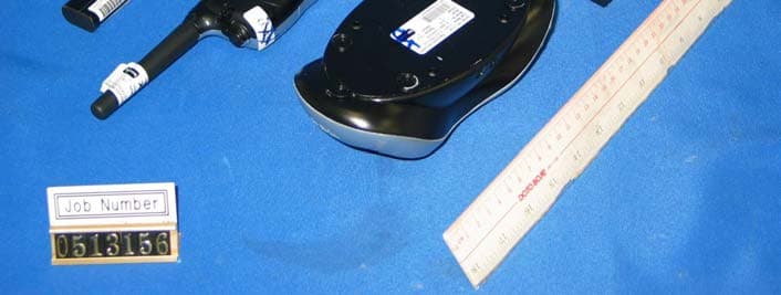
Click to zoom
Application Details
- Equipment Class
- FRF - Part 95 Family Radio Face Held Transmitter
- Date of Grant
- Dec 15, 2005
- Application Purpose
- Original Equipment
- Date of Application
- Sep 19, 2005
- Equipment Note
- Transmitter Portion of Two Way Radio w/ FRS & GMI
- Frequency Range
- 467.56250000 - 467.71250000
- Company
- Giant Electronics Ltd
- Country
- Hong Kong
Documents & Files
Document Text
Text extracted from the exhibit documents filed with the FCC. Open a document above to read the original.
Cover Letter(s)
The content of this document is Giant Electronics Ltd.'s intellectual property and is the property of Giant. It is to be treated as strictly confidential and is not to be disclosed, reproduced, or used except as authorized in writing by Giant Electronics Ltd. In connection with the manufacture, maintenance and use of the Giant equipment to which it pertains. Copyright @Giant Electronics Ltd. All rights reserved. Re: FCC ID: K7GR1080 Pursuant to 47 CFR 0.459, Giant Electronics Ltd. request confidential protection of the following documents submitted electronically in furtherance of the above-reference application as containing propriety information listed below: ■ Schematic ■ Block Diagram ■ Operational Description This information represents intellectual property of Giant Electronics Ltd. and it is subject to competition. This information should not be made routinely available for public inspection, and Giant Electronics Ltd. reserves the right to discern which parties can obtain access to this information. Dated this 7 th day of July, 2005 By: YK Ling. Signature Printed Title : Electronic Engineer Confidentiality Request Letter
External Photos
INTERTEK TESTING SERVICES External Photos FCC ID: K7GR1080 external photos - 1 of 1 External Photo - Front External Photo - Rear
Internal Photos
INTERTEK TESTING SERVICES Internal photos FCC ID: K7GR1080 internal photos - 1 of 6 Internal Photo - 1 Internal Photo - 2 INTERTEK TESTING SERVICES Internal photos FCC ID: K7GR1080 internal photos - 2 of 6 Internal Photo - 3 Internal Photo - 4 INTERTEK TESTING SERVICES Internal photos FCC ID: K7GR1080 internal photos - 3 of 6 Internal Photo - 5 Internal Photo - 6 INTERTEK TESTING SERVICES Internal photos FCC ID: K7GR1080 internal photos - 4 of 6 Internal Photo - 7 Internal Photo - 8 INTERTEK TESTING SERVICES Internal photos FCC ID: K7GR1080 internal photos - 5 of 6 Internal Photo - 9 Internal Photo - 10 INTERTEK TESTING SERVICES Internal photos FCC ID: K7GR1080 internal photos - 6 of 6 Internal Photo - 11
Parts List/Tune Up Info
GIANT ELECTRONICS LTD. Title: Alignment Procedure Revision No.: 02 Model: R1070/R1080 Date: May06, 2005 Page: 1 / 5 A. PCB LEVEL (Test Condition: under CH15, Supply=5.2Vdc) NO ITEM ALIGNMENT METHOD REMARK 1. LCD display (Should enter test mode) 1. Press and hold the ‘+’ key and ‘Menu’ key together. 2. Turn on the radio power until a good key chirp is heard, and the backlight is on for about 500 ms . finally, the LCD should be display ‘ 1 CH ’. 3. Press ‘-’ key , then all LCD segments should be anticlockwise displayed. 4. Finally, all the LCD segments should be shown for about 500ms as follows: 218 88. . 2. Standby current 1. Set A-METER, and RX mode. 2. Check the standby current <80mA DC. 3. Talk on current (Power supply 5.2V DC) 1. Set A-METER, and TX mode @50ohm load. 2. Set channel to 15, Check the talk on current <1800mA. 3. Set channel to 14, Check the talk on current <800mA. 4. VCO 1. Set RX or TX mode 2. Check TP503 to provide 0.7~2.3 VDC. 3. Adjust L509 to provide 2.2 ± 0.1VDC at TP503 if VCO level are more than 2.4VDC on CH14. 5. TX Power (Power supply 5.2V DC) 1. Set TX mode CH15, Check the transmit Hi-power to provide < 3.49W ERP. 2. Set CH15 Low power mode, Adjust VR503 to transmit Low-power to provide <0.44W ERP. 3. Set TX mode CH14, Check the transmit power to provide <0.44W ERP. Test Voltage is 6.0V 6. TX Frequency 1. Set TX mode 2. Adjust VC501 to provide 462.5500MHz ± 50Hz. 7. CTCSS Tone Frequency 1. Set CH15/CODE1 and Tx mode. 2. Check CTCSS tone frequency to be within 66.8 Hz to 67.2Hz. 1. Set AF level at 50mv;1KHz,Adjust VR101 to provide Max TX deviation 2.05KHz to 2.15KHz. 1. FILTER SET: 1.1.HPF 50Hz 1.2.LPF 15KHz 1.3. PK + 8. TX Modulation & distortion 2. Check input Mic level in 3~15 mV to provide normal deviation 1.5KHz. 3. Check the demodulation distortion <= 6%. 4. Audio Frequency Response. a) Input a 2.0mV 1KHz audio frequency to TP116 and press ‘PTT’ switch. b) Check the response compare to 1KHz tone. i) 500Hz : -6.0 dB to –12.0 dB. ii) 2.5KHz : +1.0 dB to +7.0 dB FILTER SET: 1.HPF 300Hz 2.LPF 3KHz 3. PK + 9. CDCSS Frequency 1. Set TX mode 2. Set CH15/CODE39, check Octal Code to be 023 FILTER SET: 1.Input Level: 0.9KHz 10. CTCSS Tone Dev. 5. Set CH15/CODE1 、 AF input level to off, check DEV to be 300Hz~ 650Hz. 6. Set CH14/CODE38 、 AF input level to off, check DEV to be 300Hz~ 650Hz. FILTER SET: 1. <20HZ~300HZ 2.750μs De-emp ON 7. PK+ 8. FM DEV. AVG ON GIANT ELECTRONICS LTD. Title: Alignment Procedure Revision No.: 02 Model: R1070/R1080 Date: May06, 2005 Page: 2 / 5 A. PCB LEVEL (Test Condition: under CH15) NO ITEM ALIGNMENT METHOD REMARK 11. VOX Detector 1. Set VOX level at 1. 2. Set AF level at 11 +/- 1 mV,1KHz at TP116. 3. Unit start to transmit. 4. Set AF level at 10 +/- 1mV,1KHz at TP116. 5. Unit stop transmit. 6. Set VOX level at 2. 7. Set AF level at 8.0 +/-1mV,1KHz at TP116. 8. Unit start to transmit. 9. Set AF level at 7 .0+/- 1mV,1KHz at TP116 . 10. Unit stop transmit. 11. Set VOX level at 3 12. Set AF level at 5.0 +/- 1mV,1KHz at TP116 . 13. Unit start to transmit. 14. Set AF level at 4.0+/- 1mV,1KHz at TP116. 15. Unit stop transmit. 12. IVOX Detector As same as item 11 13. Rx Audio test 1. Set RX mode CH7. 2. Set SG RF level to –50dBm with 1.5KHz deviation 1KHz modulation Signal. 3. Adjust L517 to provide minimum distortion & max output level at TP117. 4. Rotate the volume switch to the position, which give a Max audio output at TP117. 5. Check Max audio output level >1400mV. 6. Check Rx current <150mA. 7. Check the 1KHz distortion <= 5%. 8. Set SG RF level to –118dBm with 1.5kHz deviation at 1KHz audio frequency. a). Check SINAD sensitivity <= -118dBm. @12dB SINAD at TP117. 9. Audio frequency response. a) Set SG RF level to –50dBm with 1.5kHz deviation at 1KHz audio frequency. b) Rotate the volume switch to the position, which give an output 100mV±5mV at TP117. c) Vary the audio frequency from 300Hz to 3KHz. d) Check the RX response compare to 1KHz tone. i) 500Hz : -5.0 dB to -11.0 dB. ii) 2.5KHz : -10.0 dB to –20.0dB. 10. Maximum and Minimum Audio Output Power. a) Set SG RF level to –50dBm with 1.5kHz deviation at 1KHz audio frequency. b) Rotate the volume switch to the position, which give a maximum output . c) Check the voltage at TP117 >1400mV. d) Set maximum audio output to 0dB, rotate the volume switch to the position, which give a minimum output. e) Check the minimum voltage -23dB to -40dB at TP117 GIANT ELECTRONICS LTD. Title: Alignment Procedure Revision No.: 02 Model: R1070/R1080 Date: May06, 2005 Page: 3 / 5 A. PCB LEVEL (Test Condition: under CH15) NO ITEM ALIGNMENT METHOD REMARK 14. Noise- Detector 1. Set SG to –120dBm with 1.5KHz deviation., 1KHz AF on CH7. 2. Press ”Mon” key and Adjust the RF level of SG to make the radio output to 8dB SINAD, then adjust the VR502 to the radio for transient state @ 8dB SINAD. 3. Check high state @ 6 to 13dB SINAD. 15. CTCSS Tone Detect 1. Set CH15/CODE1 and SG to –60dBm with 67Hz tone frequency, 400Hz deviation. 2. Check the Pin22 of IC101 to have square-wave, and low for RF modulation off. 3. Repeat item 1 and 2 for code38 (250.3Hz). 4. Repeat item 1 ~ 3 for CH14. 16. Quiet Noise Detect 1. Set unit to quiet noise mode 2. Set CH15/CODE1and SG to –60dBm with 67Hz tone frequency, 400Hz deviation and 55 Hz audio frequency, 1K deviation.. 3. 55 Hz tone frequency appear on TP117 . 17. Normal Batter level Detect 1. If the battery voltage level less than 4.25V, the battery icon should be displayed as . 2. If the battery voltage level more than 5.4V, the battery icon should be displayed as . 3. If the battery voltage level less than 4.05V, the radio should be closed 18. SCAN 1. Set SG RF level to –50dBm with 500Hz deviation, 100Hz modulation. 2. Press "Mon" key. 3. Unit shows channels 9 and code 13. GIANT ELECTRONICS LTD. Title: Alignment Procedure Revision No.: 02 Model: R1070/R1080 Date: May06, 2005 Page: 4 / 5 B. CASING LEVEL NO ITEM ALIGNMENT METHOD REMARK 1. Current Consumption 1. Set A-METER. With volu…
Text truncated - open the document above for the full version.
Parts List/Tune Up Info
Giant Electronics Ltd. Level Item Description Qty U/M Schema----- ---- ----------- - ------ - --- ------ Paren R1080 FRS RADIO USA MASTER SILVER EA1 R1080B BASE UNIT (ALL) 1 EA0.2 R1080BC BASE CASING (ALL) 1 EA..3 R1080BCXXX BASE CASING COMMON 1 EA..3 R1080BC4SV BASE CASING SILVER 1 EA0.2 R1080B1 BASE RF & MAIN PCB (ALL) 1 EA..3 R1080B1XXXU BASE RF & MAIN UNIQUE PART 1 EA...4 R1080B1SU BASE RF & MAIN SMT UNIQUE PART 1 EA....5 R1080B1SBU BASE RF & MAIN SMT BOTTOM UNIQUE PART 1 EA....5 R1080B1STU BASE RF & MAIN SMT TOP UNIQUE PART 1 EA...4 KEJW-SA28BK STRAND WIRE UL1007 #28 BLACK 0.04 M SP-...4 KEJW-SA28RD STRAND WIRE UL1007 #28 RED 0.04 M SP+...4 KESP-122-3 SPERKER 32 OHM 0.5W ASAHI-EP LEAD-FREE 1 EA SPK101...4 KESP-172 MIC DB C9745 DD422LF-Q050 42dB 1 EA MIC101...4 KESP-172-B MIC KISS-JIA ECM KSJ9745P 0 EA MIC101...4 KEC-E107CRMKA CAP. ELECT. 6.3V M% 100UF 1 EA C812...4 KEC-E107KRM0505 CAP. ELECT 4V M 100UF 5X5MM 2 EA C200,C704...4 KEC-E227CRM0605 CAP. ELECT 6.3V M 220UF 6X5MM 1 EA C509...4 KEC-E227DRMKA CAP. ELECT. 10V M% 220UF 2 EA C108,C111...4 KECF-0163-A2 CRYSTAL FILTER FT21M07A 21.4M FRONTER 1 EA BPF502...4 KECF-0166-A-1 CERAMIC FILTER CFT450HT-1 HUATAO 1 EA BPF503...4 KED-LC102 LCD 38.0X28.0X2.0mm SHANTOU 1 EA LCD101...4 KEJ-225 JACK DC-290-002-00 SUN RISE 1 EA J101...4 KEJ-308 DIA 2.5mm EARPHONE JACK ST-101 1 EA...4 KEJ-469 CONNECTOR 4PINS 1 EA J103...4 KEJW-FC182 HEAT SEAL H=12MM P=1.4MM L=18MM 12PINS 1 EA FOR PCB-LCD...4 KEOE-OT482 JTB 450KHZ CERAMIC DISCRIMINATOR 1 EA L517...4 KEOE-OT493 RED BACK-LIGHT BOARD 1 EA...4 KEPC-949 PCB FR4 30mmX15mm 1.2mm PTT BOARD 1 EA...4 KEX-C074-1 CERAMIC RESONATOR 4MHZ +/-0.2% 1 EA X101....5 KEPC-948-1 PCB RF 123.20X46.75X1.2mm 4LAYER FR4 1 EA..... KCD-KPT2012EC LED CHIP KPT-2012EC RED 1 EA D101..... KCC-TR003-A CAP.CHIP TR1 10P ECRJA010A11 PANASONIC 1 EA VC501..... KCC-TR003 CAP. CHIP TR1MMER 10PF TZBX4100AA110 0 EA VC501..... KCC-100FBCOGEYB CAP.CER.CHIP 50V COG B 10PF 1 EA C503..... KCC-100FCNPOMUG CAP.CER. CHIP 50V NPO C% 10pF 1 EA C809..... KCC-101FJCOGGNG CAP CER CHIP 50V COG +/-5% 100PF EYANG 31 EA C123,C106,C152,C155,C166,C178,C505,C546,C547,C552 C571,C572,C575,C576,C580,C582,C600,C603,C608,C560C611,C119,C114,C149,C109,C802,C805,C581,C180,C604C4 ..... KCC-101FJNPOMUG CAP.CER.CHIP 50V CH J% 100PF MURATA 0 EA C123,C106,C152,C155,C166,C178,C505,C546,C547,C552 C571,C572,C575,C576,C580,C582,C600,C603,C608,C560C611,C119,C114,C149,C109,C802,C805,C581,C180,C604C4 ..... KCC-102FKBGNG CAP CER CHIP 50V X7R +/-10% 0.001u EYANG 4 EA C135,C174,C565,C117..... KCC-102FKBMUG CAP.CER.CHIP 50V B K% 0.001UF MURATA 0 EA C135,C174,C565,C117..... KCC-102FRJNPOB CAP. CER CHIP 50V CH J 0.001UF 1 EA C534 R1080 BOM.xls....BOMX32O373745 Print 2005-7-7 Page 1 of 6 Giant Electronics Ltd. Level Item Description Qty U/M Schema----- ---- ----------- - ------ - --- ------ ..... KCC-103BKBMUG CAP. CER. CHIP 10V X7R K 0.01UF 16 EA C127,C175,C622,C551,C705,C105,C629,C513,C514,C517 R125,C169,C121,C10,C557,C1 ..... KCC-103FRKBB CAP. CER. CHIP 50V B K% 0.01UF 2 EA C510,C511..... KCC-104BKBMUG CAP. CER. CHIP 10V X7R K 0.1UF 12 EA C129,C141,C156,C562,C563,C568,C574,C186,C118,C803 C804,C115 ..... KCC-104DZFEYG CAP CER CHIP 16V Y5V Z 0.1uF EYANG 4 EA C165,C558,C189,C573..... KCC-104DZFMUG CAP.CER.CHIP 16V F Z% 0.1UF MURATA 0 EA C165,C558,C189,C573,C544..... KCC-105BZY5VPAB CAP CER CHIP 10V Y5V 1uF Z PANASONIC 1 6 EA C197,C124,C113,C120,C528,C7..... KCC-105BRZFB CAP. CER. CHIP 10V Y5V Z% 1UF 0 EA C197,C124,C113,C120,C528..... KCC-105CZY5VPAG CAP CER CHIP 6.3V Y5V 1uF Z PANASONIC 0 5 EA C177,C559,C193,C191,C606..... KCC-105CZY5VMUG CAP CER CHIP 6.3V Y5V 1uF Z 0402 MURATA 0 EA C177,C559,C193,C191,C606..... KCC-106BZBPAM-1 CAP CER CHIP 10V Y5V 10uF Z PANASONIC M 4 EA C801,C806,C561,C148..... KCC-106BRZFM-1 CAP. CER. CHIP 10V F Z% 10UF 0 EA C801,C806,C561,C148..... KCC-106BZY5VPAM CAP CER CHIP 10V Y5V 10uF Z PANASONIC 2 2 EA C545,C812..... KCC-106BRZFF CAP CER CHIP 10V F Z 10UF 0 EA C545,C812..... KCC-109FCNPOMUG CAP.CER.CHIP 50V CH C% 1PF MURATA 0.6 EA C586 FOR MATCH C1/C4/-2/-4 CRYSTAL..... KCC-120FJNPOMUG CAP.CER.CHIP 50V CH J% 12PF MURATA 2 EA C522,C531..... KCC-120FRJNPOE CAP. CER. CHIP 50V CH J% 12PF 1 EA C506..... KCC-150FJNPOMUG CAP.CER.CHIP 50V CH J% 15PF MURATA 1.5 EA C588 FOR MATCH C3/-3 CRYSTAL,C578 C587 FOR C3/-3 CRYSTAL ..... KCC-150FRJNPOE CAP. CER. CHIP 50V CH J% 15PF 1 EA L523..... KCC-153DKBGNG CAP CER CHIP 16V X7R +/-10% 0.015u EYANG 1 EA C170..... KCC-153DKBMUG CAP. CER. CHIP 16V B K 0.015UF MURATA 0 EA C170..... KCC-159FRCNPOE CAP. CER. CHIP 50V CH C% 1.5PF 1 EA C621..... KCC-180FJNPOMUG CAP.CER.CHIP 50V CH J% 18PF MURATA 0.6 EA C587 FOR MATCH C4/-4 CRYSTAL C588 FOR MATCH C4/-4 CRYSTAL ..... KCC-200FRJNPOE CAP. CER. CHIP 50V CH J% 20PF 1 EA C2..... KCC-209FBCOGMUG CAP. CHIP 50V COG +/-0.1P 2PF 0402 1 EA C554..... KCC-221FJCOGGNG CAP CER CHIP 50V COG +/-5% 220PF EYANG 3 EA C521,C512,C516..... KCC-221FJNPOMUG CAP.CER. CHIP 50V NPO J% 220pF 0 EA C521,C512,C516..... KCC-222BKBMUG CAP. CER. CHIP 10V X7R K 0.0022UF 3 EA C566,C567,C171..... KCC-223DKBEYG CAP CER CHIP 16V B K 22NF 5 EA C6,C136,C138,C167,C530..... KCC-223DKBMUG CAP.CER.CHIP 16V B K% 22NF MURATA 0 EA C6,C136,C138,C167,C530..... KCC-240FJNPOMUG CAP.CER.CHIP 50V CH J% 24PF MURATA 1.3 EA C564,C587 FOR MATCH C1/-2 CRYSTAL..... KCC-270FJNPOMUG CAP. CER. CHIP 50V NPO J 27P 0402 1 EA C179..... KCC-271FJNPOMUG CAP.CER.CHIP 50V CH J% 270PF MURATA 1 EA C163..... KCC-273DKBEYG CAP CER CHIP 16V X7R K 0.027UF EYANG 1 EA C116..... KCC-309FCNPOMUG CAP.CER.CHIP 50V CH C% 3PF MURATA 0.3 EA C589 FOR C3/-3 CRYSTAL..... KCC-309FRCNPOE CAP. CER. CHIP 50V CH C% 3PF 1 EA C507..... KCC-330FRJNPOE CAP. CER. CHIP 50V CH J% 33PF 2 EA C504,C515..... KCC-333BKBEYG CAP CER CHIP 10V X7R K 0.033UF EYANG 2 EA C122,C196..... KCC-333BKBMUG CAP. CER. CHIP 10V X7R K 0.033UF 0 EA C122,C196..... KCC-334DRZFB CAP. CER. CHIP 16V F Z% 0.33UF 1 EA C570..... KCC-339FBCOGEYG CAP CER CHIP 50V COG B 3.3PF 1 EA C525..... KCC-369FBCOGMUG CAP CER CHIP 3.6P…
Text truncated - open the document above for the full version.
RF Exposure Info
FCC ID. : K7GR1080 Report No.: EME-050759 Page 1 of 75 0597 ILAC MRA Specific Absorption Rate (SAR) Test Report for Giant Electronics Ltd. on the Two Way Radio With GMRS and FRS Model Number: R1080, R1070 Test Report: EME-050759 Issue date: July 29, 2005 Total No of Pages Contained in this Report: 75 Tested by: Kevin Chen Reviewed by: Jerry Liu Review Date: July 29, 2005 All services undertaken are subject to the following general policy: Reports are submitted for exclusive use of the client to whom they are addressed. Their significance is subject to the adequacy and representative character of the samples and to the comprehensiveness of the tests, examinations or surveys made. This report shall not be reproduced except in full, without written consent of Intertek Testing Services, Taiwan Ltd. FCC ID. : K7GR1080 Report No.: EME-050759 Page 2 of 75 Table of Contents 1.0 General information .................................................................................................... 3 1.1 Client Information....................................................................................................... 3 1.2 Equipment under test (EUT) ....................................................................................... 4 1.3 Test plan reference ...................................................................................................... 4 1.4 Test configuration ....................................................................................................... 5 1.4.1 Support equipment & EUT antenna position ....................................................... 5 1.4.2 Test Condition ...................................................................................................... 6 1.5 Modifications required for compliance....................................................................... 6 2.0 SAR Evaluation........................................................................................................... 7 2.1 SAR Limits .................................................................................................................7 2.2 Configuration Photographs ......................................................................................... 8 2.3 SAR measurement system ........................................................................................ 11 2.4 SAR measurement system validation ....................................................................... 12 2.4.1 System Validation result ..................................................................................... 13 2.4.2 System Performance Check result...................................................................... 15 2.5 Test Result................................................................................................................. 17 3.0 Test Equipment ......................................................................................................... 19 3.1 Equipment List .......................................................................................................... 19 3.2 Tissue Simulating Liquid .......................................................................................... 20 3.2.1 Body Tissue Simulating Liquid for evaluation test ............................................ 20 3.2.2 Head Tissue Simulating Liquid for System performance Check and evaluation test 20 3.2.3 Body Liquid results ............................................................................................ 21 3.2.4 Head Liquid results ............................................................................................ 22 3.3 E-Field Probe and 450 Balanced Dipole Antenna Calibration ................................. 23 4.0 Measurement Uncertainty ......................................................................................... 24 5.0 Warning Label Information - USA ........................................................................... 26 6.0 References .................................................................................................................27 7.0 Document History ..................................................................................................... 28 APPENDIX A - SAR Evaluation Data ........................................................................... 29 APPENDIX B - Photographs .......................................................................................... 46 APPENDIX C - E-Field Probe and 450MHz Balanced Dipole Antenna Calibration Data52 FCC ID. : K7GR1080 Report No.: EME-050759 Page 3 of 75 1.0 General information The Giant sample device, model # R1080, R1070 was evaluated in accordance with the requirements for compliance testing defined in FCC OET Bulletin 65, Supplement C (Edition 01-01). Testing was performed at the Intertek Testing Services facility in Hsinchu, Taiwan. The maximum output power declared by the Giant. The EUT was evaluated in a face-held configuration with the front of the radio placed parallel to the outer surface of the planar. A 2.5cm separation distance was maintained between the front side of the EUT and the outer surface of the planar phantom for the duration of the test. The EUT was tested in a body-worn configuration with the rear of the radio placed parallel to outer surface of the planar phantom. The attached plastic belt-clip was touching the planar phantom. The EUT was evaluated for body-worn SAR with the microphone accessory. For the evaluation, the dosimetric assessment system INDEXSAR SARA2 was used. The phantom employed was the box phantom of 6 mm thick in one wall. The total uncertainty for the evaluation of the spatial peak SAR values averaged over a cube of 1g tissue mass had been assessed for this system to be ±20.6%. The device was tested in unmodulated continuous transmit operation (Continuous Wave at 100% duty cycle) with the transmit key constantly depressed. For a push-to-talk device, the 50% duty cycle compens…
Text truncated - open the document above for the full version.
RF Exposure Info
FCC ID. : K7GR1080 Report No.: EME-050759 Page 1 of 76 0597 ILAC MRA Specific Absorption Rate (SAR) Test Report for Giant Electronics Ltd. on the Two Way Radio With GMRS and FRS Model Number: R1080, R1070 Test Report: EME-050759 Issue date: July 29, 2005 Total No of Pages Contained in this Report: 76 Tested by: Kevin Chen Reviewed by: Jerry Liu Review Date: July 29, 2005 All services undertaken are subject to the following general policy: Reports are submitted for exclusive use of the client to whom they are addressed. Their significance is subject to the adequacy and representative character of the samples and to the comprehensiveness of the tests, examinations or surveys made. This report shall not be reproduced except in full, without written consent of Intertek Testing Services, Taiwan Ltd. FCC ID. : K7GR1080 Report No.: EME-050759 Page 2 of 76 Table of Contents 1.0 General information .................................................................................................... 3 1.1 Client Information....................................................................................................... 3 1.2 Equipment under test (EUT) ....................................................................................... 4 1.3 Test plan reference ...................................................................................................... 4 1.4 Test configuration ....................................................................................................... 5 1.4.1 Support equipment & EUT antenna position ....................................................... 5 1.4.2 Test Condition ...................................................................................................... 6 1.5 Modifications required for compliance....................................................................... 6 2.0 SAR Evaluation........................................................................................................... 7 2.1 SAR Limits .................................................................................................................7 2.2 Configuration Photographs ......................................................................................... 8 2.3 SAR measurement system ........................................................................................ 11 2.4 SAR measurement system validation ....................................................................... 12 2.4.1 System Validation result ..................................................................................... 13 2.4.2 System Performance Check result...................................................................... 15 2.5 Test Result................................................................................................................. 17 3.0 Test Equipment ......................................................................................................... 19 3.1 Equipment List .......................................................................................................... 19 3.2 Tissue Simulating Liquid .......................................................................................... 20 3.2.1 Body Tissue Simulating Liquid for evaluation test ............................................ 20 3.2.2 Head Tissue Simulating Liquid for System performance Check and evaluation test 20 3.2.3 Body Liquid results ............................................................................................ 21 3.2.4 Head Liquid results ............................................................................................ 22 3.3 E-Field Probe and 450 Balanced Dipole Antenna Calibration ................................. 23 4.0 Measurement Uncertainty ......................................................................................... 24 5.0 Warning Label Information - USA ........................................................................... 26 6.0 References .................................................................................................................27 7.0 Document History ..................................................................................................... 28 APPENDIX A - SAR Evaluation Data ........................................................................... 29 APPENDIX B - Photographs .......................................................................................... 46 APPENDIX C - E-Field Probe and 450MHz Balanced Dipole Antenna Calibration Data53 FCC ID. : K7GR1080 Report No.: EME-050759 Page 3 of 76 1.0 General information The Giant sample device, model # R1080, R1070 was evaluated in accordance with the requirements for compliance testing defined in FCC OET Bulletin 65, Supplement C (Edition 01-01). Testing was performed at the Intertek Testing Services facility in Hsinchu, Taiwan. The maximum output power declared by the Giant. The EUT was evaluated in a face-held configuration with the front of the radio placed parallel to the outer surface of the planar. A 2.5cm separation distance was maintained between the front side of the EUT and the outer surface of the planar phantom for the duration of the test. The EUT was tested in a body-worn configuration with the rear of the radio placed parallel to outer surface of the planar phantom. The attached plastic belt-clip was touching the planar phantom. The EUT was evaluated for body-worn SAR with the microphone accessory. For the evaluation, the dosimetric assessment system INDEXSAR SARA2 was used. The phantom employed was the box phantom of 6 mm thick in one wall. The total uncertainty for the evaluation of the spatial peak SAR values averaged over a cube of 1g tissue mass had been assessed for this system to be ±20.6%. The device was tested in unmodulated continuous transmit operation (Continuous Wave at 100% duty cycle) with the transmit key constantly depressed. For a push-to-talk device, the 50% duty cycle compens…
Text truncated - open the document above for the full version.
RF Exposure Info
FCC ID. : K7GR1080 Report No.: EME-050759 Page 1 of 85 0597 ILAC MRA Specific Absorption Rate (SAR) Test Report for Giant Electronics Ltd. on the Two Way Radio With GMRS and FRS Model Number: R1080, R1070 Test Report: EME-050759 Issue date: Dec. 9, 2005 Total No of Pages Contained in this Report: 85 Tested by: Kevin Chen Reviewed by: Jerry Liu Review Date: Dec. 9, 2005 All services undertaken are subject to the following general policy: Reports are submitted for exclusive use of the client to whom they are addressed. Their significance is subject to the adequacy and representative character of the samples and to the comprehensiveness of the tests, examinations or surveys made. This report shall not be reproduced except in full, without written consent of Intertek Testing Services, Taiwan Ltd. FCC ID. : K7GR1080 Report No.: EME-050759 Page 2 of 85 Table of Contents 1.0 General information .................................................................................................... 3 1.1 Client Information....................................................................................................... 3 1.2 Equipment under test (EUT) ....................................................................................... 4 1.3 Test plan reference ...................................................................................................... 4 1.4 Test configuration ....................................................................................................... 5 1.4.1 Support equipment & EUT antenna position ....................................................... 5 1.4.2 Test Condition ...................................................................................................... 6 1.5 Modifications required for compliance....................................................................... 6 2.0 SAR Evaluation........................................................................................................... 7 2.1 SAR Limits .................................................................................................................7 2.2 Configuration Photographs ......................................................................................... 8 2.3 SAR measurement system ........................................................................................ 11 2.4 SAR measurement system validation ....................................................................... 12 2.4.1 System Validation result ..................................................................................... 13 2.4.2 System Performance Check result...................................................................... 15 2.5 Test Result................................................................................................................. 18 3.0 Test Equipment ......................................................................................................... 21 3.1 Equipment List .......................................................................................................... 21 3.2 Tissue Simulating Liquid .......................................................................................... 22 3.2.1 Body Tissue Simulating Liquid for evaluation test ............................................ 22 3.2.2 Head Tissue Simulating Liquid for System performance Check and evaluation test 23 3.2.3 Body Liquid results ............................................................................................ 24 3.2.4 Head Liquid results ............................................................................................ 26 3.3 E-Field Probe and 450 Balanced Dipole Antenna Calibration ................................. 28 4.0 Measurement Uncertainty ......................................................................................... 29 5.0 Warning Label Information - USA ........................................................................... 31 6.0 References ..............…
Text truncated - open the document above for the full version.
Contact Information
Applicant
Yumin Zou(A. Manager)
Technical Contact
Intertek Testing Services Hong Kong Ltd.Tommy Leung
[email protected]852-21738538
2/F., Garment Centre, · Kowloon, · Hong Kong
Non-Technical Contact
Intertek Testing Services Hong Kong Ltd.Tommy Leung
[email protected]852-21738538
Test Firm
Intertek Testing Services Hong KongBilly Chow
Technical Specifications
| # | Rule Parts | Frequency Range | Power Output | Emission | Tolerance |
|---|---|---|---|---|---|
| 2 | 95B | 467.5625 MHz - 467.7125 MHz | 440.00 mW | 5K8F3E | 2.1 ppm |
Other Applications from Giant Electronics Ltd

K7GMDBJJPR
Jun 24, 2012Two Way Radio - FRS
Equipment Class
FRF - Part 95 Family Radio Face Held Transmitter
K7GMTCEJ
Apr 26, 2012Two Way Radio with GMRS and FRS
Equipment Class
CXX - Communications Rcvr for use w/ licensed Tx and CBs
K7GMDBJJ
Mar 01, 2012Two Way Radio with GMRS and FRS
Equipment Class
FRF - Part 95 Family Radio Face Held Transmitter
K7GMSFGJ
Mar 10, 2011Two Way Radio with Weather Band
Equipment Class
CXX - Communications Rcvr for use w/ licensed Tx and CBs
K7GT2007
Apr 08, 2010Two Way Radio with GMRS and FRS
Equipment Class
FRF - Part 95 Family Radio Face Held Transmitter