K7GT542014-Channel Family Radio Service
Giant Electronics Ltd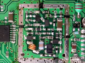
Click to zoom
Application Details
- Equipment Class
- FRF - Part 95 Family Radio Face Held Transmitter
- Date of Grant
- May 20, 2002
- Application Purpose
- Original Equipment
- Date of Application
- Nov 12, 2001
- Equipment Note
- 14-Channel Family Radio Service
- Frequency Range
- 462.56250000 - 467.71250000
- Company
- Giant Electronics Ltd
- Country
- Hong Kong
Documents & Files
Document Text
Text extracted from the exhibit documents filed with the FCC. Open a document above to read the original.
Users Manual
2 3 1 Table of Contents YOUR NEW RADIO......................2 BATTERIES.................................3 To Install:................................................3 Radio Etiquette:.......................................3 BELT CLIP..................................4 To Attach:...............................................4 To Remove:............................................4 FRONT COVER...........................4 To Remove:............................................4 To Attach:...............................................4 TO COMMUNICATE.....................5 Turn The Radio On:................................6 Monitor Button:.......................................6 Channel Busy Indicator:.........................6 Adjust The Volume:................................6 Menu/Lock Button:..................................7 Set The Channel:....................................7 Set The Code:.........................................7 Call Tone:................................................8 Set The Call Tone:..................................8 “Roger” Beep:.........................................9 Set “Roger” Beep:..................................9 Scan Advance.....................................10 Hands-Free Use With Accessories.....11 Setting Sensitivity Level.......................12 Sending Messages:..............................12 Battery Meter:.......................................13 Low Battery Alert:................................13 ACCESSORIES.........................13 To Use Audio Accessories:.................13 CARE OF YOUR RADIO.............14 SAFETY AND GENERAL INFORMATION..........................15 LIMITED WARRANTY................23 2 Your New Radio Motorola Talkabout T5320, T5410 and T5420 radios operate on Family Radio Service (FRS) designated frequencies. This license-free, short range, two- way radio service was established specifically for family and group recreational use. Use of this radio outside the country where it was intended to be distributed is subject to government regulations and may be prohibited. 3 Batteries T5320, T5410 and T5420 radios operate with 3 AA alkaline batteries providing approximately 30 hours of use. That is almost 3 hours of talk and over 27 hours of standby time. To Install: 1. With back of radio facing you, flip Battery Cover Latch up to release. Lift cover off. Fig. 1. 2. Insert 3 AA batteries as shown. Fig. 2. 3. Reposition Battery Cover, flip Battery Cover Latch down to secure. Note: Your radio will retain its settings for 10 minutes after the batteries are removed. After 10 minutes, your radio will go back to its factory settings. Radio Etiquette: Your radio has multiple channels shared on a “take turns” basis. This means other groups may be talking on the channels. For uninterrupted communications, do not talk over someone who is already using the channel – your message may not be completely heard. Try changing the channel to avoid channel congestion or use the Monitor button to check for channel activity. If you hear static while holding down the Monitor button the channel is clear for use. 4 Note: Since the channels are shared, your conversations will not be private and you may hear others talking. Belt Clip Motorola T5320, T5410 and T5420 radios come with a swivel belt clip. To Attach: 1. Align belt clip post with hole in the radio back. 2. Gently push until it clicks into place. Fig. 3. To Remove: 1. Push release tab on top of belt clip down to release catch. 2. Pull belt clip from the radio back. Front Cover The T5320, T5410 and T5420 radios have a removable front cover that allows you to customize your radio to your lifestyle. Do not operate the radio without the cover. To Remove: 1. With a 1/8 inch flathead screwdriver, push down and towards you in between the top of the front cover and the radio. Fig. 4. 2. Pull the sides of the removable cover away from the radio. To Attach: 1. Reinsert housing tabs. 2. Press down to snap cover into place. 5 To Communicate Read this manual carefully and make sure you know how to properly operate radio before use. Motorola 6 Talkabout two-way radios have 14 channels. To communicate with others, all radios in your group must be set to the same channel and Interference Eliminator Code. Turn The Radio On: 1. Rotate Power/Volume knob clockwise until you hear a click. Radio will beep and LED Indicator Light will flash to confirm. All icons on the display will light up briefly, then the current channel and code will show. LED will flash every three seconds. 2. To turn radio off, rotate Power/Volume knob counter clockwise until you hear a click and display disappears. Monitor Button: The Scan/Monitor button on T5410 (Monitor ONLY button on T5320 and T5420) lets you hear the radio’s volume level when you are not receiving so you can adjust the volume. It is also used to check activity on current channel before transmitting. To use the Monitor feature, press and hold the Scan/Monitor button on T5410 (Monitor ONLY button on T5320 and T5420). Channel Busy Indicator: The radio also has a Channel Busy Indicator where the LED will also flash twice per second to indicate the channel frequency is in use. Adjust The Volume: Rotate Power/Volume knob while holding down the Scan/Monitor button on T5410 (Monitor ONLY button on T5320 and T5420) until you reach a comfortable listening level. Rotate knob clockwise to increase and counter clockwise to decrease volume. 7 Time-out Timer: The Time-out Timer feature helps extend battery life by preventing accidental transmission. The radio will emit a continuous warning tone after the Push-To-Talk button is pressed for 60 continuous seconds and will stop transmitting. Menu/Lock Button: You can be sure your menu settings won’t be changed accidentally. Just turn on the menu lock by pressing the Menu button for six seconds. Now you’ll see a lock on the display. You can turn off the menu lock by pressing the Menu button for six seconds again. The lock icon disappear…
Text truncated - open the document above for the full version.
Internal Photos
Model : Motorola T5320 Test SetupFCCID : K7GT5420 Internal Photo - 1 Internal Photo - 2 Model : Motorola T5320 Test SetupFCCID : K7GT5420 Internal Photo – 3 Model : Motorola T5400 Test SetupFCCID : K7GT5420 Internal Photo - 1 Internal Photo - 2 Model : Motorola T5400 Test SetupFCCID : K7GT5420 Internal Photo – 3
Test Report
Modulation Frequency Response 0.00 0.50 1.00 1.50 2.00 20070012001700220027003200370042004700 Modulation Frequency (Hz) Modulation Index (%) Modulation Frequency Response 0.00 0.50 1.00 1.50 2.00 2.50 20070012001700220027003200370042004700 Modulation Frequency (Hz) Frequency Deviation (kHz)
Test Report
Modulation Limiting Characteristic 0.00 0.50 1.00 1.50 2.00 2.50 475767778797107117127137 Modulation Input (dBSPL) Frequency Deviation (kHz) 500Hz 1000Hz 2500Hz 3125Hz
Test Report
• The test results rep orted in this rep ort shall refer only to the samp le actually tested and shall not refer or be deemed a refer to bulk from which such a samp le may be said to have been obtained. • This rep ort shall not be rep roduced excep t in full without p rior authorization from Intertek Testing Services Hong Kong Limit ed • For Terms And Conditions of the services, it can be p rovided up on request. Inte rte k Te sting Se rvice s Hong Kong Ltd. 2/F., Garment Centre, 576 Castle Peak Road, Kowloon, Hong Kong. Tel: (852) 2173 8888 Fax: (852) 2785 5487 Giant Electronics Limited Application For Certification (FCC ID: K7GT5420) November 13, 2001 WO# 0112403 WL/Agnes November 13, 2001 INTERTEK TESTING SERVICES FCC ID: K7GT5420 i SUMMARY OF CONTENTS LIST OF EXHIBITS EXHIBIT 1 :General Description EXHIBIT 2 :System Test Configuration EXHIBIT 3 :RF Power Output EXHIBIT 4 :Modulation Characteristics EXHIBIT 5 :Occupied Bandwidth EXHIBIT 6 :Spurious Emission EXHIBIT 7 :Frequency Stability EXHIBIT 8 :Technical Specifications EXHIBIT 9 :Product Labelling EXHIBIT 10 :Photographs EXHIBIT 11: Instruction Manual EXHIBIT 12: Tune Up Procedure EXHIBIT 13: Part List EXHIBIT 14: RF Exposure Info INTERTEK TESTING SERVICES FCC ID: K7GT5420 ii MEASUREMENT/TECHNICAL REPORT Application: Giant Electronics Limited Trade Name/Model No : MOTOROLA T5300 MOTOROLA T5320 MOTOROLA T5400 MOTOROLA T5410 MOTOROLA T5420 Date: November 13, 2001 This report concerns (check one:)Original Grant X Class II Change Equipment Type: Family Radio Service, FRS Deferred grant requested per 47 CFR 0.457(d)(1)(ii)? Yes No X If yes, defer until: date Company Name agrees to notify the Commission by: date of the intended date of announcement of the product so that the grant can be issued on that date. Report prepared by:Wilson Loke Intertek Testing Services 2/F., Garment Centre, 576 Castle Peak Road, Kowloon, Hong Kong. Phone: 852-2173-8575 Fax:852-2745-8306 INTERTEK TESTING SERVICES FCC ID: K7GT5420 iv Table of Contents 1.0 General Description ................................................................................................................ 2 1.1 Product Description................................................................................................................ 2 1.2 Related Submittal(s) Grants....................................................................................................3 1.3 Test Methodology................................................................................................................... 3 1.4 Test Facility............................................................................................................................ 3 2.0 System Test Configuration ................................................................................................... 5 2.1 Justification............................................................................................................................. 5 2.2 EUT Exercising Software ....................................................................................................... 6 2.3 Special Accessories ................................................................................................................ 6 2.4 Equipment Modification.........................................................................................................6 3.0 RF Output Power (Section 95.639(d)) ................................................................................. 8 4.0 Modulation Characteristics (Section 95.637(a)) .............................................................. 12 4.1 Modulation Frequiency Response ........................................................................................ 13 4.2 Modulation Limiting Characteristic...................................................................................... 15 4.3 Audio Low Pass Filter Response.......................................................................................... 17 5.0 Occupied Bandwidth (Section 95.633(c)) ......................................................................... 19 6.0 Spurious Emission (Section 95.635(b)) ............................................................................. 21 6.1 Field Strength of Spurious Radiation .................................................................................... 22 7.0 Frequency Stability (Section 95.627) ................................................................................ 28 7.1 Frequency Tolerance ............................................................................................................29 7.2 Temperature Extreme Condition .......................................................................................... 31 7.3 Voltage Extreme Condition .................................................................................................. 34 8.0 Technical Specifications ..................................................................................................... 37 9.0 Product Labelling ............................................................................................................... 41 10.0 Equipment Photographs .................................................................................................... 44 11.0 Instruction Mannal ............................................................................................................. 46 12.0 Tune Up Procedure ............................................................................................................. 48 13.0 Part List ................................................................................................................................50 14.0 RF Exposure Info ................................................................................................................. 52 INTERTEK TESTING SERVICES FCC ID: K7GT5420 v List of attached file Exhibit typeFile DescriptionFilename Operation DescriptionTechnical …
Text truncated - open the document above for the full version.
Test Report
Audio Low Pass Filter Response -70 -60 -50 -40 -30 -20 -10 0 110100 Frequency (kHz) dB relative to 1 kHz LPF Response TIA/EIA-603
Test Setup Photos
Test SetupFCCID : K7GT5420 Radiated -front Radiated - rear
Contact Information
Applicant
Yumin Zou(A. Manager)
Technical Contact
Intertek Testing Services Hong Kong LtdWilson Loke
[email protected](852) 21738575
2/F., Garment Centre · Kowloon · Hong Kong
Non-Technical Contact
Intertek Testing Services Hong Kong LtdWilson Loke
[email protected](852) 21738575
Test Firm
Intertek Testing Services Hong KongBilly Chow
Technical Specifications
| # | Rule Parts | Frequency Range | Power Output | Emission | Tolerance |
|---|---|---|---|---|---|
| 1 | 95B | 462.5625 MHz - 467.7125 MHz | 480.00 mW | 10K5F3E | 2.5000000000 ppm |
Other Applications from Giant Electronics Ltd

K7GMDBJJPR
Jun 24, 2012Two Way Radio - FRS
Equipment Class
FRF - Part 95 Family Radio Face Held Transmitter
K7GMTCEJ
Apr 26, 2012Two Way Radio with GMRS and FRS
Equipment Class
CXX - Communications Rcvr for use w/ licensed Tx and CBs
K7GMDBJJ
Mar 01, 2012Two Way Radio with GMRS and FRS
Equipment Class
FRF - Part 95 Family Radio Face Held Transmitter
K7GMSFGJ
Mar 10, 2011Two Way Radio with Weather Band
Equipment Class
CXX - Communications Rcvr for use w/ licensed Tx and CBs
K7GT2007
Apr 08, 2010Two Way Radio with GMRS and FRS
Equipment Class
FRF - Part 95 Family Radio Face Held Transmitter