K7GT59XXTransmitter Portion of FRS + GMRS
Giant Electronics Ltd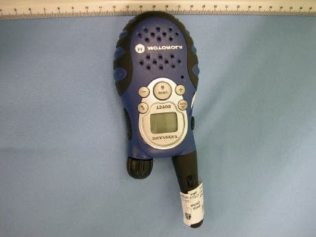
Click to zoom
Application Details
- Equipment Class
- FRF - Part 95 Family Radio Face Held Transmitter
- Date of Grant
- May 08, 2003
- Application Purpose
- Original Equipment
- Date of Application
- May 08, 2003
- Equipment Note
- Transmitter Portion of FRS + GMRS
- Frequency Range
- 467.56250000 - 467.71250000
- Company
- Giant Electronics Ltd
- Country
- Hong Kong
Documents & Files
Document Text
Text extracted from the exhibit documents filed with the FCC. Open a document above to read the original.
Users Manual
Model T5900, T5920, and T5950 @6864110W17@ 6864110W17-O 031048o 4110w17o.book Page 1 Monday, January 20, 2003 12:20 PM Introduction 1 P r e lim ina r y IntroductionCongratulations on your purchase of a Motorola product!Product registration is an important step. Registering helps us facilitate warranty service and permits us to contact you should your Motorola product require an update or other service. To register your product on-line, visit www.motorola.com/warranty/radios . Please retain your original dated sales receipt for your records. For warranty service of your Motorola product, you will need to provide a copy of your dated sales receipt to confirm warr anty status. Registration is not required for warranty coverage. For a copy of a large-print version of this guide, or for product-related questions, call: 1-800-353-2729 in the USA 1-888-390-6456 TTY (Text Telephone) On the Web: www.motorola.com/talkabout 4110w17o.book Page 1 Monday, January 20, 2003 12:20 PM Contents 2 P r e lim ina r y Contents Introduction . . . . . . . . . . . . . . . . . . . . . 1Safety and General In formation . . . . 3 FCC Licensing Information . . . . . . . 11Control Buttons . . . . . . . . . . . . . . . . 12Getting Started . . . . . . . . . . . . . . . . . 13 Installing the AA Batteries . . . . . . . . 13Installing the NiCd Battery Pack . . . 14Battery Meter . . . . . . . . . . . . . . . . . . 14Using the Desk Stand Charger (Optional Accessory) . . . . . . . . . . 14 Attaching the Belt Clip . . . . . . . . . . . 16Removing the Belt Clip . . . . . . . . . . 16Turning Your Radio On and Off . . . . 16Setting the Volume . . . . . . . . . . . . . 16Setting a Channel . . . . . . . . . . . . . . 16Channels and Frequencies . . . . . . . 17 Talking and Listening . . . . . . . . . . . . 18 Monitor Button . . . . . . . . . . . . . . . . . 18 Special Features . . . . . . . . . . . . . . . . 19 Interference Eliminator Codes . . . . . 19Push to Talk Timeout Timer . . . . . . . 19Keypad Lock . . . . . . . . . . . . . . . . . . 19Enhanced Scanning . . . . . . . . . . . . . 20 Scan Advance . . . . . . . . . . . . . . . . . .21Removing Channels from the Scan List (Scan Delete) . . . . . . . . . . . . .21 Alerts . . . . . . . . . . . . . . . . . . . . . . . . . .22 Channel Busy Indicator . . . . . . . . . . .22Setting and Transmitting Call Tones . 22Transmitting a Talk Confirmation Tone . . . . . . . . . . . . . . . . . . . . . . .23 QT Noise Filtering . . . . . . . . . . . . . . .23VibraCall® Alert (Models T5920 and T5950 Only) . . . . . . . . . . . . . . . . .24 Accessories . . . . . . . . . . . . . . . . . . . .25 Using Audio Accessories . . . . . . . . . .25Handsfree Use Without Accessories (iVOX) . . . . . . . . . . . . . . . . . . . . . .25 Handsfree Use with Accessories (VOX) . . . . . . . . . . . . . . . . . . . . . .26 Setting the Sensitivity Level . . . . . . .26 4110w17o.book Page 2 Monday, January 20, 2003 12:20 PM Safety and General Information 3 P r e lim ina r y Safety and General InformationImportant Information on Safe and Efficient OperationRead This Information Before Using Your RadioThe information provided in this document supersedes the general safety information contained in user guides published prior to July 2000.Transmit and Receive ProcedureYour two-way radio contains a transmitter and a receiver. To control your exposure and ensure compliance with the general population/uncontrolled environment exposure limits, always adhere to the following procedure: • Transmit no more than 50% of the time. • To transmit (talk), press the Push to Talk (PTT) button. • To receive calls, release the PTT button. Transmitting 50% of the time, or less, is important because the radio generates measurable RF energy exposure only when transmitting (in terms of measuring standards compliance).Exposure to Radio Frequency EnergyYour Motorola radio is designed to comply with the following national and international standards and guidelines regarding exposure of human beings to radio frequency electromagnetic energy:• United States Federal Communications Commission, Code of Federal Regulations; 47 CFR part 2 sub-part J 4110w17o.book Page 3 Monday, January 20, 2003 12:20 PM Safety and General Information 4 P r e lim ina r y • American National Standards Institute (ANSI)/Institute of Electrical and Electronic Engineers (IEEE) C95. 1-1992 • Institute of Electrical and Electronic Engineers (IEEE) C95.1-1999 Edition • International Commission on Non-Ionizing Radiation Protection (ICNIRP) 1998 • Ministry of Health (Canada) Safety Code 6. Limits of Human Exposure to Radio Frequency Electromagnetic Fields in the Frequency Range from 3 kHz to 300 GHz, 1999 • Australian Communications Authority Radiocommunications (Electromagnetic Radiation - Human Exposure) Standard 2001 (applicable to wireless phones only) • ANATEL, Brasil Regulatory Authority, Resolution 256 (April 11, 2002) “additional requirements for SMR, cellular, and PCS product certification.” To assure optimal radio performance and make sure human exposure to radio frequency electromagnetic energy is within the guidelines set forth in the above standards, always adhere to the following procedures.Portable Radio Operation and EME ExposureAntenna CareUse only the supplied or an approved rep lacement antenna. Unauthorized antennas, modifications, or attachments could damage the radio and may violate FCC regulations. DO NOT hold the antenna when the radio is “IN USE.” Holding the antenna affects the effective range. 4110w17o.book Page 4 Monday, January 20, 2003 12:20 PM Safety and General Information 5 P r e lim ina r y Two-Way Radio OperationWhen using your radio as a traditional two-way radio, hold the radio in a vertical position with the microp hone one to two inches (2.5 to 5 cm) away from the lips . Body-Worn Operation To maintain compliance with FCC/Health Canada RF exposure guidelines, if you wear a radio on your body when transmitting, always place the radio in a Motor…
Text truncated - open the document above for the full version.
Cover Letter(s)
To: 'Phang Wayne-EWP004' Cc: 'Johnson Ricky-ERJ003'; 'Ramnath Mike-EMR003'; TCB_Admin ITS/ES-Crt Subject: RE: SAR summery report for Motorola T59XX GMRS radio Wayne: Review of your SAR report is complete, and we note the following: 1. This probe calibration data is absent: - axial, hemispherical isotropy plots - dynamic range and linearity plot Please provide this information, or indicate how compliance with requirements is documented. A copy of the SPEAG calibration plots is acceptable. 2. This SAR computation is absent: - coarse scanning procedures used to locate peak SAR - interpolation procedures used to identify peak SAR - fine scanning procedures used to determine peak 1-g SAR - integration procedures used to determine highest 1-g and 10-g SAR in cube Please provide this information, as supplementary documentation. 3. Please indicate how the minimum 15 cm liquid depth in the flat phantom was assessed and assured. 4. Please indicate which accessories if any are metallic. 5. Section 8 of the test report lists the highest face-held SAR values calculated as 0.92(1-g) and 0.63 (10-g). The table in Section 7.1 lists SAR values of 1.10 (1-g) and 0.753 (10-g). Please explain the differences. 6. A source-based, time-averaged duty cycle of 50% for SAR calculation is allowed for push-to-talk transmitters. Your calculations do not appear to include this factor, based on a CW test signal. Please explain why a 50% factor does not apply for this device. If it does apply, you should re-compute the maximum SAR values accordingly. The reported 1-g value of 1.55 is marginal to the limit of 1.6 W/g. Certification can be completed as soon as the above issues are resolved. Sincerely, Roland Gubisch Intertek TCB
Cover Letter(s)
CGISS EME response to TCB correspondence dated 5/8/03 from Roland Gubisch of ITS 5/9/03 Q1. This probe calibration data is absent: - axial, hemispherical isotropy plots - dynamic range and linearity plot Please provide this information, or indicate how compliance with requirements is documented. A copy of the SPEAG calibration plots is acceptable. R1. Attached herein are the requested additional SPEAG calibration plots. Q2. This SAR computation is absent: - coarse scanning procedures used to locate peak SAR - interpolation procedures used to identify peak SAR - fine scanning procedures used to determine peak 1-g SAR - integration procedures used to determine highest 1-g and 10-g SAR in cube Please provide this information, as supplementary documentation. R2. The system used to assess compliance performance of FCC ID: K7GT59XX was a DASY 3 system. This is a generally accepted industry standard system. The information being requested can be located in the application notes section of the DASY 3 Dosimetric Assessment System Software Manual. Specifically reference “The application note: Data Storage and Evaluation” as well as “Application Note: Validation and System Check” sections. A PDF file containing the relevant sections of the application notes are attached herein. Q3. Please indicate how the minimum 15 cm liquid depth in the flat phantom was assessed and assured. R3. All CGISS EME phantoms are marked with a 15cm reference line. The liquid depth is referenced to this line during each daily system performance check and adjustments are made as needed. Q4. Please indicate which accessories if any are metallic. R4. The following accessories contain metallic material: - Model NTN9392B - Swivel Belt Clip - internal spring is metal. - Model NTN9153A - FR50 carry case - metallic material in the area of the antenna loop - 50982 - Fanny Pack - metallic zippers - All audio accessories contain metallic contents. Q5. Section 8 of the test report lists the highest face-held SAR values calculated as 0.92(1-g) and 0.63 (10-g). The table in Section 7.1 lists SAR values of 1.10 (1-g) and 0.753 (10-g). Please explain the differences. R5. Please reference the table labeled “Compliance Assessment at the Face; CW mode” in section 7.1 on page 17 of 17. This table shows the maximum calculated results that correspond to the results reported in section 8.0 on page 17 of 17. Note that the 2.5cm assessment reported in the “Compliance Assessment at the abdomen...” used FCC body tissue parameters while the results in the “Compliance Assessment at the Face...” used IEEE head tissue parameters. Also note that the test position information indicated in the “Compliance Assessment at the Face...” results incorrectly shows “against the phantom”. The correct test position is with 2.5 cm separation distance. The revised report attached herein reflects this correction. Q6. A source-based, time-averaged duty cycle of 50% for SAR calculation is allowed for push-to- talk transmitters. Your calculations do not appear to include this factor, based on a CW test signal. Please explain why a 50% factor does not apply for this device. If it does apply, you should re-compute the maximum SAR values accordingly. The reported 1-g value of 1.55 is marginal to the limit of 1.6 W/g. R6. A 50% duty cycle is applicable to this product. The maximum calculated results presented in the submitted report reflect 50% duty cycle performance. The equation presented in section 7.3 should have accounted for the 50% duty cycle. The report has been revised to correct this error. Please find the revised report attached herein.
External Photos
Test Setup FCCID : K7GT59XX External Photo (T5900) – front External Photo (T5900) – rear Test Setup FCCID : K7GT59XX External Photo (T5950) – front External Photo (T5950) - rear
Internal Photos
Test Setup FCCID : K7GT59XX Internal Photo (T5900) – 1 Internal Photo (T5900) – 2 Test Setup FCCID : K7GT59XX Internal Photo (T5900) – 3 Internal Photo (T5900) – 4 Test Setup FCCID : K7GT59XX Internal Photo (T5900) – 5 Test Setup FCCID : K7GT59XX Internal Photo (T5950) - 1 Internal Photo (T5950) – 2 Test Setup FCCID : K7GT59XX Internal Photo (T5950) – 3 Internal Photo (T5950) – 4 Test Setup FCCID : K7GT59XX Internal Photo (T5950) – 5
Parts List/Tune Up Info
Tune Procedure 1) TX VCO ADJUSTMENT a. connect the DC voltmeter at TP503 b. press and hold PTT button c. adjust L509 to 1.0VDC +/-0.2V at CH1 2) FREQUENCY ADJUSTMENT a. connect the frequency counter meter to TP501 b. adjust C501 to TX frequency +/-200Hz 3) TX POWER CHECK a. connect the RF level meter to the TP501 b. press and hold PTT button c. check the TX power <1000mW at CH1 and <500mW at CH14 4) DEVIATION LIMITING AND MIC SENSITIVITY a. connect the deviation meter to TP501 b. apply audio signal 1KHz 25mVrms to TP116 c. press and hold PTT button d. adjust VR101 to 2.2KHz DEV +/-0.2KHz e. check mic sensitivity between 1mVrms and 10mVrms at 1.5KHz DEV 5) LOW PASS FILTER MEASUREMENT a. open R161 and connect 1UF capacitor and 150KOhm resistor in series to the point between C174 and C175 b. input 500mVrms to the point of 1UF capacitor and measure the frequency response at IC103 pin 7 6) DCS MEASUREMENT a. connect the deviation meter to TP501 b. press and hold PTT button c. adjust VR501 to 0.6KHz DEV +/-0.1KHz • TO PRESS AND HOLD THE PTT BUTTON FOR TX MODE TESTING • TO PRESS AND HOLD MENU AND +, THEN POWER UP FOR RADIO TEST MODE • THE RADIO CAN TRANSMITTING WITHOUT TIMEOUT UNDER TEST MODE
RF Exposure Info
Certificate Number: 1449-02 CGISS EME Test Laboratory 8000 West Sunrise Blvd Fort Lauderdale, FL. 33322 S.A.R. EME Compliance Test Report Part 1 of 2 Date of Report: May 9, 2003 Report Revision: Rev. A Manufacturer: Motorola Product Description: UHF/FRS/GMRS 22 channel; w/ display; 1W FCC ID: K7GT59XX Tested Model(s): HCUE1102A Certified Model(s): HCUE1102A Form-SAR-Rpt-Rev. 2.00 Page 1 of 17 Test Period: 4/4/03 – 4/8/03 EME Tech: Ed Church / Clint Miller EME Eng.: Deanna Zakharia (Elect. Principle Staff Eng.) Author: Michael Sailsman Global EME Regulatory Affairs Liaison Note: Based on the information and the testing results provided herein, the undersigned certifies that when used as stated in the operating instructions supplied, said product complies with the national and international reference standards and guidelines listed in section 2.0 of this report. Signature on File 5/9/03 ____________________________________________________________ _________________________ Ken Enger Date Approved Senior Resource Manager, Laboratory Director, CGISS EME Lab Note: This report shall not be reproduced without written approval from an officially designated representative of the Motorola EME Laboratory. TABLE OF CONTENTS Part 1of 2 1.0 Introduction 2.0 Reference Standards and Guidelines 3.0 Description of Test Sample 3.1 Test Signal 3.2 Test Output Power 4.0 Description of Test Equipment 4.1 Description of S.A.R Measurement System 4.2 Description of Phantom 4.2.1 Flat Phantom 4.2.2 SAM phantom 4.3 Simulated Tissue Properties 4.3.1 Type of Simulated Tissue 4.3.2 Simulated Tissue Composition 4.4 Test condition 5.0 Description of Test Procedure 5.1 Device Test Positions 5.1.1 Abdomen 5.1.2 Head 5.1.3 Face 5.2 Test Position Photographs 5.3 Probe Scan Procedures 6.0 Measurement Uncertainty 7.0 S.A.R. Test Results 7.1 S.A.R. results 7.2 Peak S.A.R. location 7.3 Highest S.A.R. results calculation methodology 8.0 Conclusion Part 2of 2 Appendix A: Power Slump Data Appendix B: Data Results Appendix C: Dipole System Performance Check Results Appendix D: Calibration Certificates Appendix E: Illustration of Body-worn Accessories Appendix F: Accessories and options test status and separation distances Form-SAR-Rpt-Rev. 2.00 Page 2 of 17 REVISION HISTORY Date Revision Comments 5/8/03 O Pilot Results 5/9/03 A Revised text in section 4.1. Corrected error in the test position information reported within the “compliance assessment at the face...” table in section 7.1. Corrected error in the formula in section 7.3 Form-SAR-Rpt-Rev. 2.00 Page 3 of 17 1.0 Introduction This report details the utilization, test setup, test equipment, and test results of the Specific Absorption Rate (S.A.R.) measurements performed at the CGISS EME Test Lab for model number HCUE1102A, FCC ID: K7GT59XX. The applicable exposure environment is General Population/Uncontrolled. The test results included herein represent the highest S.A.R. levels applicable to this product and clearly demonstrate compliance with FCC General Population/Uncontrolled RF Exposure limits of 1.6 mW/g per the requirements of 47 CFR 2.1093(d). 2.0 Reference Standards and Guidelines This product is designed to comply with the following national and international standards and guidelines. • United States Federal Communications Commission, Code of Federal Regulations; 47CFR part 2 sub-part J • American National Standards Institute (ANSI) / Institute of Electrical and Electronic Engineers (IEEE) C95. 1-1992 • Institute of Electrical and Electronic Engineers (IEEE) C95.1-1999 Edition • International Commission on Non-Ionizing Radiation Protection (ICNIRP) 1998 • Ministry of Health (Canada) Safety Code 6. Limits of Human Exposure to Terminal frequency Electromagnetic Fields in the Frequency Range from 3 kHz to 300 GHz, 1999 • Australian Communications Authority Terminal communications (Electromagnetic Radiation - Human Exposure) Standard 2001 • ANATEL, Brazil Regulatory Authority, Resolution 256 (April 11, 2001) "additional requirements for SMR, cellular and PCS product certification." Form-SAR-Rpt-Rev. 2.00 Page 4 of 17 3.0 Description of Test Sample FCC ID: K7GT59XX is a 22 channel super heterodyne analog FM UHF FRS/GMRS device. Both FRS and GMRS modes share the first seven channels. This device will be marketed to and used by the general population. This device may be used while held in a vertical position 2.5cm in front of the face. FCC ID: K7GT59XX is capable of operating in the 462.5625-467.7125 MHz. The rated and maximum power for FRS mode is 0.500W ERP. The rated and maximum power output for GMRS mode is 1W ERP as defined by the upper limit of the production line final test station. Form-SAR-Rpt-Rev. 2.00 Page 5 of 17 FCC ID: K7GT59XX is offered with the following options and accessories: Antenna Fixed 462-470MHz Helical ¼ wave antenna; -2dBi Batteries AA Store bought alkaline batteries HKNN4002 NiCd Rechargeable Battery Body-worn Accessories NTN9392B Swivel Belt clip NTN9399B Arm/Belt/Bike carry case (56323) NTN9153A FR50 carry case (53772) HLN8865A Waterproof bag (50983) 50982 Fanny Pack Other Attachments NTN8867A Remote Speaker Microphone (53724) NTN8868B Headset w/ swivel boom mic (53725) NTN8869B Ear bud (53726B) NTN8870C Ear bud w/ PTT microphone (53727) NTN8891B Flexible ear receiver (53728) NTN9396B Earpiece w/ boom mic (56320) NTN9156A Spirit GT headset with boom mic (53740) NTN9159B Lightweight headset with boom mic (53743) 3.1 Test Signal Test Signal mode: Transmission Mode: CW X Native Transmission TDMA: Other: Test ModeX Base Station Simulator Form-SAR-Rpt-Rev. 2.00 Page 6 of 17 3.2 Test Output Power A table of the characteristic power slump versus time is provided in Appendix A for all tested batteries. 4.0 Description of Test Equipment 4.1 Descriptions of S.A.R. Measurement System The laboratory utilizes a Dosimetric Assessment System (DASY3) S.A.R. measurement system manufactured by Schmid & Partner Engineering AG (SPEAG™), of Zurich Switzerland. The …
Text truncated - open the document above for the full version.
RF Exposure Info
Certificate Number: 1449-02 CGISS EME Test Laboratory 8000 West Sunrise Blvd Fort Lauderdale, FL. 33322 S.A.R. EME Compliance Test Report Part 2 of 2 Date of Report: May 8, 2003 Report Revision: Rev. O Manufacturer: Motorola Product Description: UHF/FRS/GMRS 22 channel; w/ display; 1W FCC ID: K7GT59XX Tested Model(s): HCUE1102A Certified Model(s): HCUE1102A Form-SAR-Rpt-Rev. 2.00 Page 1 of 33 Test Period: 4/4/03 – 4/8/03 EME Tech: Ed Church / Clint Miller EME Eng.: Deanna Zakharia (Elect. Principle Staff Eng.) Author: Michael Sailsman Global EME Regulatory Affairs Liaison Note: Based on the information and the testing results provided herein, the undersigned certifies that when used as stated in the operating instructions supplied, said product complies with the national and international reference standards and guidelines listed in section 2.0 of this report. Signature on file 5/8/03 ____________________________________________________________ _________________________ Ken Enger Date Approved Senior Resource Manager, Laboratory Director, CGISS EME Lab Note: This report shall not be reproduced without written approval from an officially designated representative of the Motorola EME Laboratory. APPENDIX A Power Slump Data/Shortened Scan Form-SAR-Rpt-Rev. 2.00 Page 2 of 33 DUT Power versus time Data Form-SAR-Rpt-Rev. 2.00 Page 3 of 33 Form-SAR-Rpt-Rev. 2.00 Page 4 of 33 Shortened Scan Results FCC ID: K7GT59XX; Test Date: 4/08/03 Motorola CGISS EME Laboratory Run #: Ab-R3-030408-07 Model #: HCUE1102A S/N #: 175WDE004S TX Freq: 462.5625 MHz Sim Tissue Temp: 20.9 (Celsius) Start Power = 953 mW ANTENNA KIT #: FIXED BATTERY KIT #: AA ALKALINE ACCESSORIES: CARRY CASE #: NTN9153A AUDIO ACCESSORIES: RSM #: NTN8867A Shortened scan reflect highest S.A.R. producing configuration; Run time 7 minutes. Representative “normal” scan run time was 20 minutes “Shortened” scan max calculated S.A.R. using S.A.R. drift: 1-g Avg. = 1.55 mW/g; 10-g Avg. = 1.043mW/g “Normal” scan max calculated S.A.R. using S.A.R. drift: 1-g Avg. = 1.36 mW/g; 10-g Avg. = 0.92 mW/g (see section 7.1 run # Ab-R3-030404-06) DUT w/ carry case against the phantom Flat Phantom; Section; Position: (90°,90°); Probe: ET3DV6 - SN1383 (Cal Date 02-26-2003); ConvF(7.50,7.50,7.50); Probe cal date: 26/02/03; Crest factor: 1.0; FCC Body 465: σ = 0.94 mho/m σ = 55.1 ρ = 1.00 g/cm3; DAE3 SN: 374 DAE CAL DATE: 02-19-03 Cube 7x7x7: SAR (1g): 2.50 mW/g, SAR (10g): 1.68 mW/g, (Worst-case extrapolation) Coarse: Dx = 15.0, Dy = 15.0, Dz = 10.0; Max at 19.5, 109.5, 3.2 Power drift: -0.73 dB Note: The shortened scan represents the highest compliance S.A.R. results Form-SAR-Rpt-Rev. 2.00 Page 5 of 33 APPENDIX B Data Results Form-SAR-Rpt-Rev. 2.00 Page 6 of 33 FCC ID: K7GT59XX; Test Date: 4/4/03 Motorola CGISS EME Laboratory RUN #: Ab-R3-030404-06 MODEL #: HCUE1102A SER #: 175WDE004S TX FREQ: 462.5625 MHz SIM TEMP: 21.0 C START PWR: .953 W ANTENNA KIT #: FIXED BATTERY KIT #: AA ALKALINE ACCESSORIES: BELT CLIP #: NTN9392B AUDIO ACCESSORIES: RSM #: NTN8867A DUT w/ belt clip against the phantom Phantom; Section; Position: (90°,90°); Probe: ET3DV6 - SN1383 (Cal Date 02-26-2003); ConvF(7.50,7.50,7.50); Probe cal date: 26/02/03; Crest factor: 1.0; FCC Body 465: σ = 0.95 mho/m ε = 55.1 ρ = 1.00 g/cm3; DAE3 SN: 374 DAE CAL DATE: 02-19-03 Cube 7x7x7: SAR (1g): 1.36 mW/g, SAR (10g): 0.945 mW/g, (Worst-case extrapolation) Coarse: Dx = 15.0, Dy = 15.0, Dz = 10.0; Max at 18.0, 97.5, 3.2 Power drift: -1.34 dB Form-SAR-Rpt-Rev. 2.00 Page 7 of 33 FCC ID: K7GT59XX; Test Date: 4/7/03 Motorola CGISS EME Laboratory RUN #: Ab-R3-030407-08 MODEL #: HCUE1102A SER #: 175WDE004S TX FREQ: 462.5625 MHz SIM TEMP: 21.1 C START PWR: .953 W ANTENNA KIT #: FIXED BATTERY KIT #: AA ALKALINE ACCESSORIES: CARRY CASE #: NTN9153A AUDIO ACCESSORIES: HEADSET /W MIC #: NTN9159B DUT w/ carry case against the phantom Phantom; Section; Position: (90°,90°); Probe: ET3DV6 - SN1383 (Cal Date 02-26-2003); ConvF(7.50,7.50,7.50); Probe cal date: 26/02/03; Crest factor: 1.0; FCC Body 465: σ = 0.93 mho/m ε = 54.8 ρ = 1.00 g/cm3; DAE3 SN: 374 DAE CAL DATE: 02-19-03 Cube 7x7x7: SAR (1g): 2.11 mW/g, SAR (10g): 1.44 mW/g * Max outside, (Worst-case extrapolation) Coarse: Dx = 15.0, Dy = 15.0, Dz = 10.0; Max at 15.0, 96.0, 3.2 Power drift: -1.00 dB Form-SAR-Rpt-Rev. 2.00 Page 8 of 33 FCC ID: K7GT59XX; Test Date: 4/7/03 Motorola CGISS EME Laboratory RUN #: Ab-R3-030407-11 MODEL #: HCUE1102A SER #: 175WDE004S TX FREQ: 462.5625 MHz SIM TEMP: 21.0 C START PWR: .953 W ANTENNA KIT #: FIXED BATTERY KIT #: AA ALKALINE ACCESSORIES: NONE AUDIO ACCESSORIES: RSM #: NTN8867A DUT w/ front facing phantom and antenna 2.5 cm Flat Phantom; Section; Position: (90°,90°); Probe: ET3DV6 - SN1383 (Cal Date 02-26-2003); ConvF(7.50,7.50,7.50); Probe cal date: 26/02/03; Crest factor: 1.0; FCC Body 465: σ = 0.93 mho/m ε = 54.8 ρ = 1.00 g/cm3; DAE3 SN: 374 DAE CAL DATE: 02-19-03 Cube 7x7x7: SAR (1g): 1.66 mW/g, SAR (10g): 1.14 mW/g, (Worst-case extrapolation) Coarse: Dx = 15.0, Dy = 15.0, Dz = 10.0; Max at 45.0, 105.0, 3.2 Power drift: -1.00 dB Form-SAR-Rpt-Rev. 2.00 Page 9 of 33 FCC ID: K7GT59XX; Test Date: 4/08/03 Motorola CGISS EME Laboratory RUN #: Face-R3-030408-09 MODEL #: HCUE1102A SER #: 175WDE004S TX FREQ: 462.5625 MHz SIM TEMP: 20.8 C START PWR: .953 W ANTENNA KIT #: FIXED BATTERY KIT #: AA ALKALINE ACCESSORIES: NONE AUDIO ACCESSORIES: NONE DUT w/ front 2.5 cm from phantom Flat Phantom; Section; Position: (90°,90°); Probe: ET3DV6 - SN1383 (Cal Date 02-26-2003); ConvF(7.50,7.50,7.50); Probe cal date: 26/02/03; Crest factor: 1.0; IEEE Head 465 MHz: σ = 0.87 mho/m ε = 43.3 ρ = 1.00 g/cm3; DAE3 SN: 374 DAE CAL DATE: 02-19-03 Cube 7x7x7: SAR (1g): 1.36 mW/g, SAR (10g): 0.938 mW/g, (Worst-case extrapolation) Coarse: Dx = 15.0, Dy = 15.0, Dz = 10.0; Max at 36.0, 102.0, 3.2 Power drift: -1.08 dB Form-SAR-Rpt-Rev. 2.00 Page 10 of 33 APPENDIX C Dipole System Performance Check Results Form-SAR-Rpt-Rev. 2.00 Page 11 of 33 SPEAG 450 MHz Dipole; …
Text truncated - open the document above for the full version.
Test Report
• The test results reported in this report shall refer only to the sample actually tested and shall not refer or be deemed a refer to bulk from which such a sample may be said to have been obtained. • This report shall not be reproduced except in full without prior authorization from Intertek Testing Services Hong Kong Limited • For Terms And Conditions of the services, it can be provided upon request. • The evaluation data of the report will be kept for 3 years from the date of issuance. Intertek Testing Services Hong Kong Ltd. 2/F., Garment Centre, 576 Castle Peak Road, Kowloon, Hong Kong. Tel: (852) 2173 8888 Fax: (852) 2371 0521 Giant Electronics Ltd. Application For Certification (FCC ID: K7GT59XX) March 21, 2003 WO# 0301749 DL/Sandy March 21, 2003 INTERTEK TESTING SERVICES FCC ID: K7GT59XX i SUMMARY OF CONTENTS LIST OF EXHIBITS EXHIBIT 1:General Description EXHIBIT 2:System Test Configuration EXHIBIT 3:RF Power Output EXHIBIT 4:Modulation Characteristics EXHIBIT 5:Occupied Bandwidth EXHIBIT 6:Spurious Emission EXHIBIT 7:Frequency Stability EXHIBIT 8:Technical Specifications EXHIBIT 9:Product Labelling EXHIBIT 10:Photographs EXHIBIT 11:Instruction Manual EXHIBIT 12:Tune Up Procedure EXHIBIT 13:Part List EXHIBIT 14:Input Current EXHIBIT 15:RF Exposure Info EXHIBIT 16:Confidentiality Request INTERTEK TESTING SERVICES FCC ID: K7GT59XX ii MEASUREMENT/TECHNICAL REPORT Application:Giant Electronics Ltd. Trade Name/Model No:MOTOROLA T5950 MOTOROLA T5900 MOTOROLA T5920 Date:March 21, 2003 This report concerns (check one:)Original Grant X Class II Change Equipment Type: GMRS + FRS Deferred grant requested per 47 CFR 0.457(d)(1)(ii)? Yes No X If yes, defer until: date Company Name agrees to notify the Commission by: date of the intended date of announcement of the product so that the grant can be issued on that date. Report prepared by:Derek Leung Intertek Testing Services 2/F., Garment Centre, 576 Castle Peak Road, Kowloon, Hong Kong. Phone:852-2173-8504 Fax:852-2371-0521 INTERTEK TESTING SERVICES FCC ID: K7GT59XX iii Table of Contents 1.0 General Description............................................................................................................2 1.1 Product Description.........................................................................................................2 1.2 Related Submittal(s) Grants..............................................................................................3 1.3 Test Methodology...........................................................................................................3 1.4 Test Facility.....................................................................................................................3 2.0 System Test Configuration.................................................................................................5 2.1 Justification......................................................................................................................5 2.2 EUT Exercising Software.................................................................................................6 2.3 Special Accessories.........................................................................................................6 2.4 Measurement Uncertainty.................................................................................................6 2.5 Equipment Modification....................................................................................................6 3.0 RF Output Power (Section 95.639(d))................................................................................8 4.0 Modulation Characteristics (Section 95.637(a))..............................................................13 4.1 Modulation Frequiency Response...................................................................................14 4.2 Modulation Limiting Characteristic..................................................................................17 4.3 Audio Low Pass Filter Response....................................................................................19 5.0 Occupied Bandwidth (Section 95.633(c)) .........................................................................21 6.0 Spurious Emission (Section 95.635(b)).............................................................................23 6.1 Field Strength of Spurious Radiation...............................................................................24 7.0 Frequency Stability (Section 95.627)................................................................................32 7.1 Frequency Tolerance......................................................................................................33 7.2 Temperature Extreme Condition.....................................................................................36 …
Text truncated - open the document above for the full version.
Contact Information
Applicant
Yumin Zou(A. Manager)
Technical Contact
Intertek Testing Services Hong Kong Ltd.Derek Leung
[email protected]852-2173-8504
2/F., Garment Centre, · Kowloon · Hong Kong
Non-Technical Contact
Intertek Testing Services Hong Kong Ltd.Derek Leung
[email protected]852-2173-8504
Test Firm
Intertek Testing Services Hong KongBilly Chow
Technical Specifications
| # | Rule Parts | Frequency Range | Power Output | Emission | Tolerance |
|---|---|---|---|---|---|
| 2 | 95B | 467.5625 MHz - 467.7125 MHz | 410.00 mW | 10K5F3E | 2.5 ppm |
Other Applications from Giant Electronics Ltd

K7GMDBJJPR
Jun 24, 2012Two Way Radio - FRS
Equipment Class
FRF - Part 95 Family Radio Face Held Transmitter
K7GMTCEJ
Apr 26, 2012Two Way Radio with GMRS and FRS
Equipment Class
CXX - Communications Rcvr for use w/ licensed Tx and CBs
K7GMDBJJ
Mar 01, 2012Two Way Radio with GMRS and FRS
Equipment Class
FRF - Part 95 Family Radio Face Held Transmitter
K7GMSFGJ
Mar 10, 2011Two Way Radio with Weather Band
Equipment Class
CXX - Communications Rcvr for use w/ licensed Tx and CBs
K7GT2007
Apr 08, 2010Two Way Radio with GMRS and FRS
Equipment Class
FRF - Part 95 Family Radio Face Held Transmitter