K7GT5X0014-Channel Family Radio Service (FRS)
Giant Electronics Ltd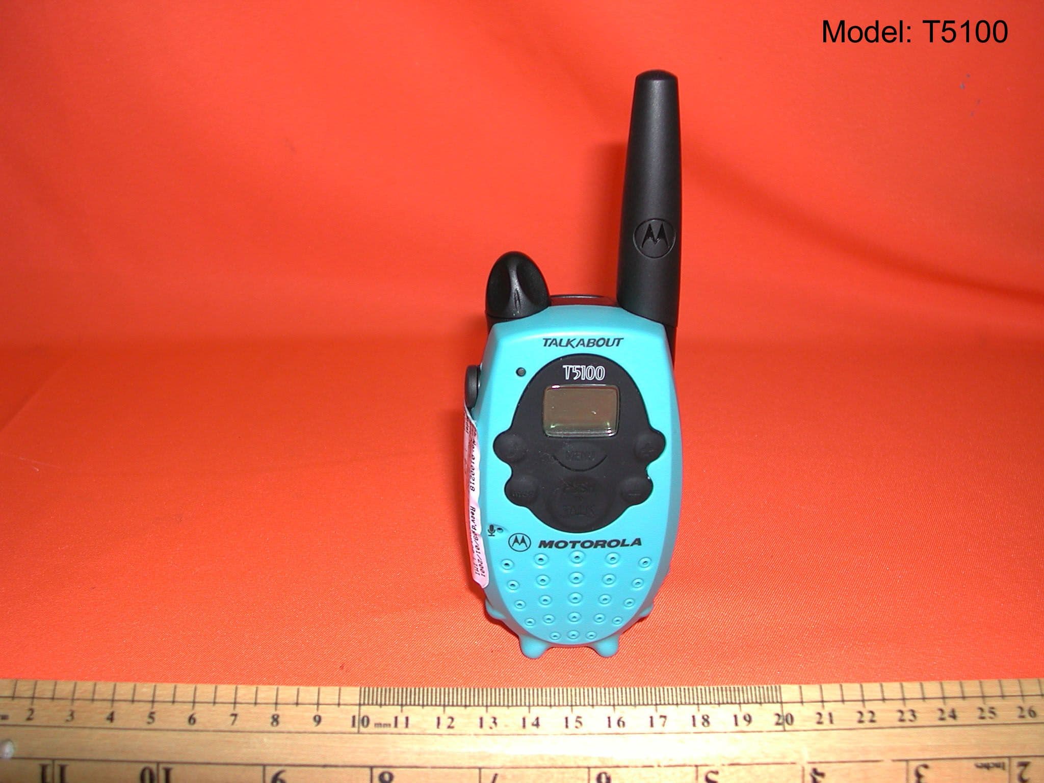
Click to zoom
Application Details
- Equipment Class
- FRF - Part 95 Family Radio Face Held Transmitter
- Date of Grant
- Apr 17, 2001
- Application Purpose
- Original Equipment
- Date of Application
- Feb 05, 2001
- Equipment Note
- 14-Channel Family Radio Service (FRS)
- Frequency Range
- 462.56250000 - 467.71250000
- Company
- Giant Electronics Ltd
- Country
- Hong Kong
Documents & Files
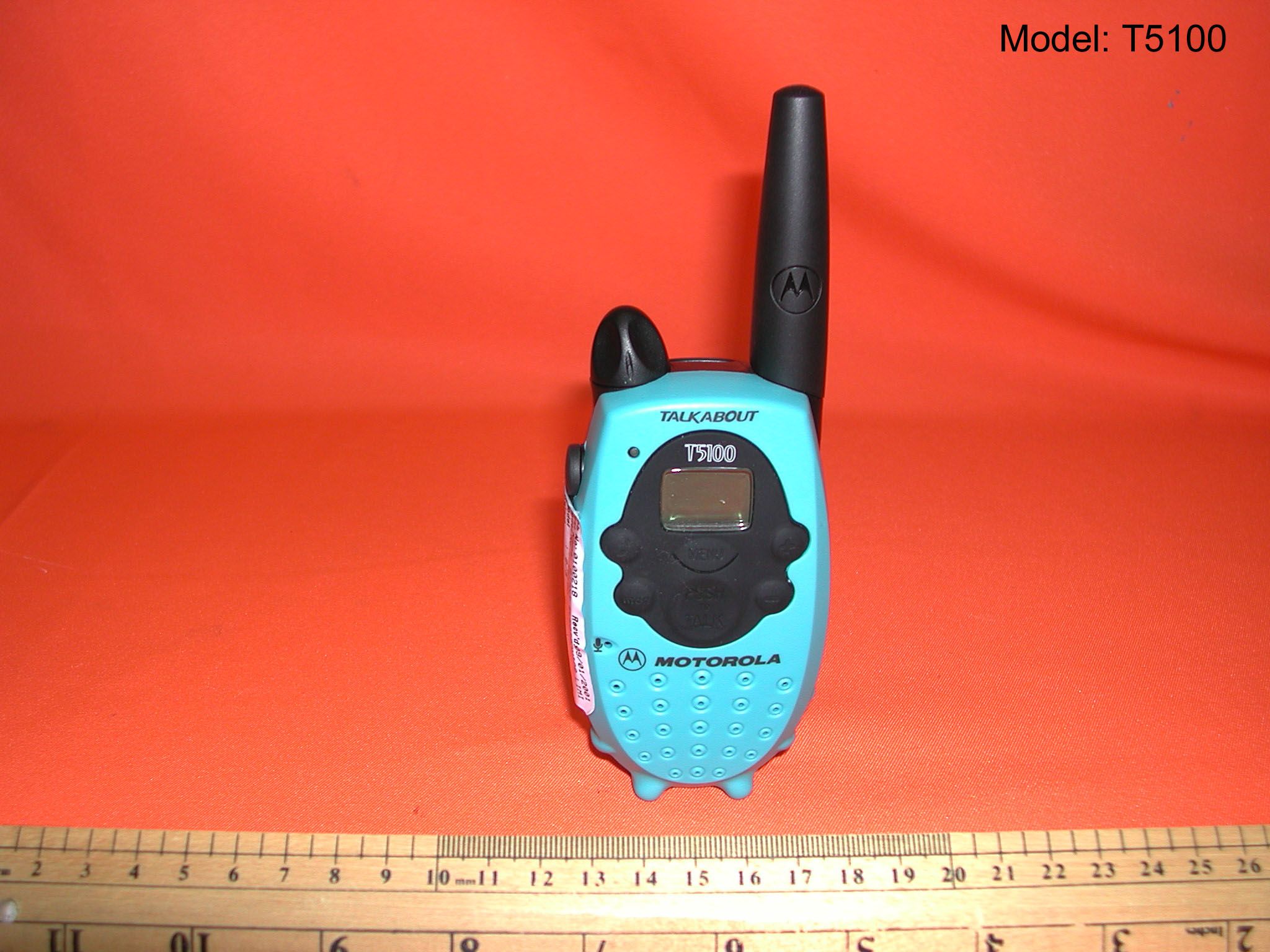
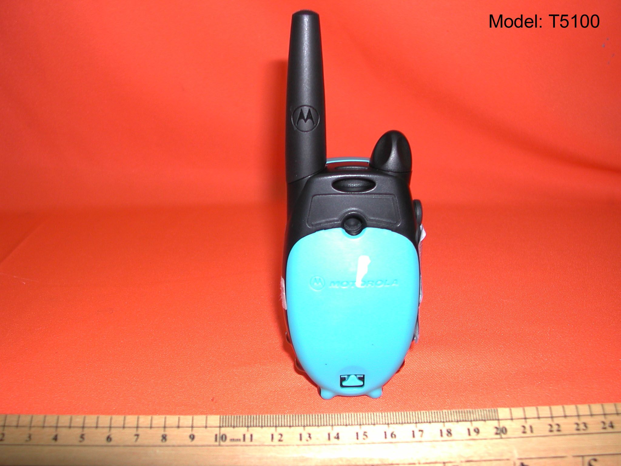
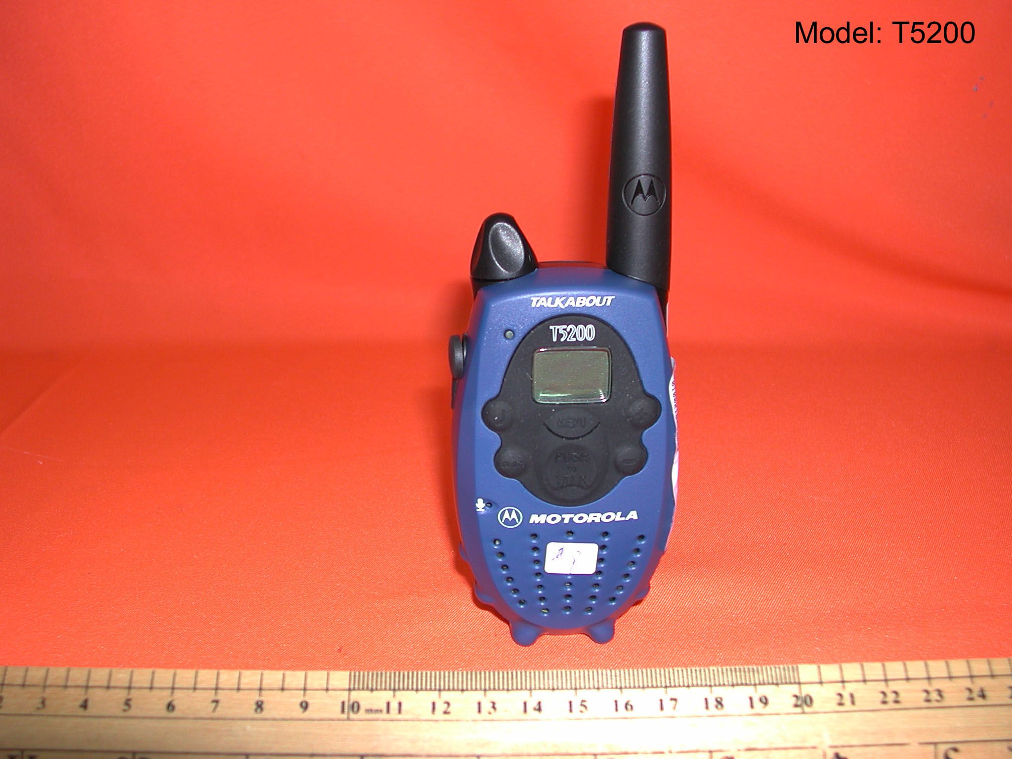
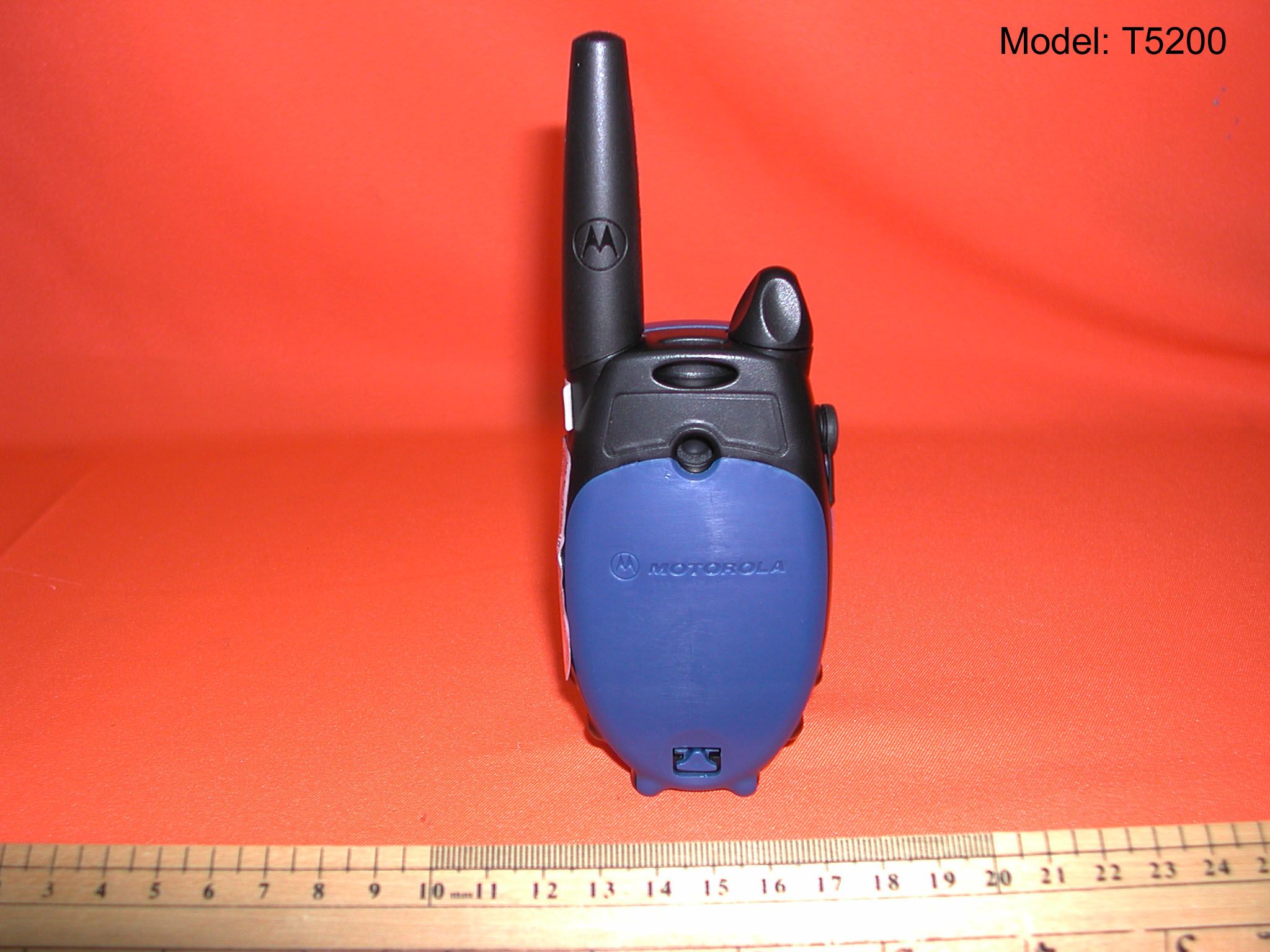
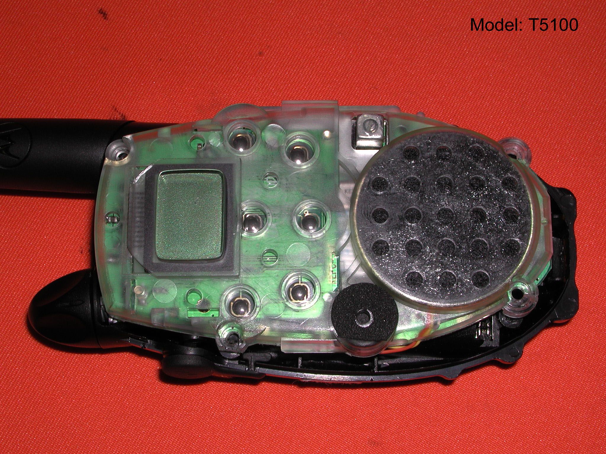
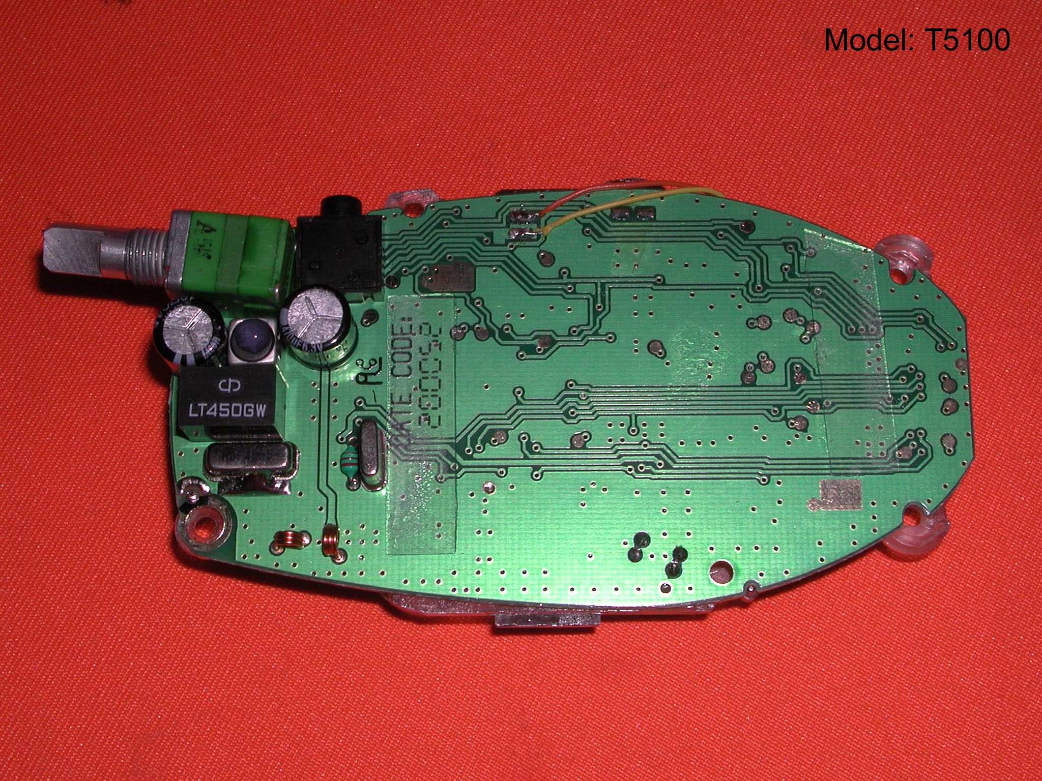
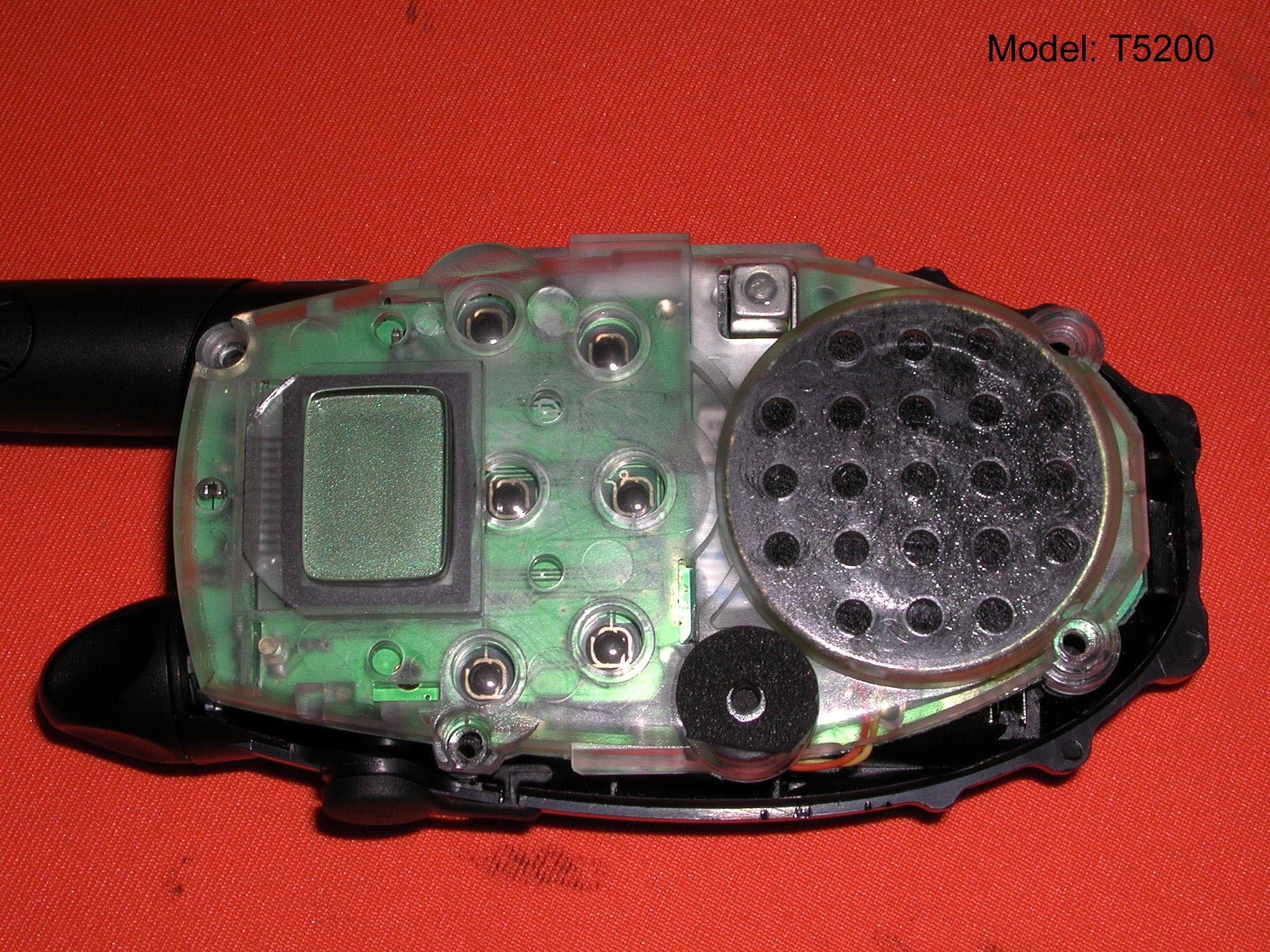
Document Text
Text extracted from the exhibit documents filed with the FCC. Open a document above to read the original.
Users Manual
T5100 Series Canada and US Visit the Motorola Website at: http://www.motorola.com Visitez notre site Web à : http://www.motorola.com Visite nuestro sitio de Motorola en la red: http://www.motorola.com Visite nosso endereço na internet: http://www.motorola.com.br T5100 Series Canada and US 1 Table Of Contents Your New Radio Radio Diagram...................................................................3 Batteries To Install ............................................................................4 Radio Etiquette..................................................................4 Belt Clip To Attach............................................................................4 To Remove.........................................................................4 To Communicate Removeable front Cover....................................................5 Turn The Radio On............................................................5 Monitor Button...................................................................5 Adjust The Volume.............................................................5 Time-out Timer...................................................................5 Set The Channel................................................................6 Set The Code.....................................................................6 Call Tone............................................................................6 Set The Call Tone..............................................................6 “Roger” Beep.....................................................................7 Sending Messages............................................................7 Battery Meter.....................................................................7 Low Battery Alert...............................................................7 To Use Audio Accessories.................................................7 Talk Range.........................................................................9 Care of Your radio..............................................................9 Safety Information Cautions and Warnings......................................................10-13 Troubleshooting Troubleshooting ................................................................14 Warranty One Year Limited Warranty................................................15 Accessories.......................................................................16 Channel Frequency Chart..................................................16 Interference Eliminator Code Chart...................................17 Specifications.....................................................................18 E N G L I S H T5100 Series Canada and US Push-To-Talk Button (PTT) 2 Your New Radio Motorola Talkabout T5100 and T5200 radios operate on Family Radio Service (FRS) designated frequencies.This license-free, short range, two-way radio service was established specifically for family and group recreational use. Use of this radio outside the country where it was intended to be distributed is subject to government regulations and may be prohibited. 3 Power/Volume Knob Accessory Jack Scroll Buttons Interference Eliminator Code* Microphone Menu/Lock Button LED Indicator Light Monitor (mon) Button Battery Cover Latch (radio back) Call Tone Button Battery Meter *T5200 Only “Roger” Beep Icon T5100 Series Canada and US Batteries T5100 and T5200 radios operate with 3 AA alkaline batteries providing approximately 30 hours of use. That is almost 3 hours of talk and over 27 hours of standby time. To Install: 1. With back of radio facing you, flip Battery Cover Latch up to release. Lift cover off. Fig. 1. 2. Insert 3 AA batteries as shown. Fig. 2. 3. Replace battery cover. Reposition Battery Cover, flip Battery Cover Latch down to secure. 5 Figure 1 4 Belt Clip Motorola T5100 and T5200 radios come with a swivel belt clip. To Attach: 1. Align belt clip post with hole in the radio back. 2. Gently push until it clicks into place. Fig. 3. To Remove: 1. Push release tab on top of belt clip down to release catch. 2. Pull belt clip from the radio back. Figure 3 Battery Cover Latch To Communicate Read this manual carefully and make sure you know how to properly operate radio before use. Motorola Talkabout two-way radios have 14 channels*. To communicate with others, all radios in your group must be set to the same channel. Other FRS radios, such as the T5200, may have Interference Eliminator Codes, which must be turned off or set to zero for proper communication with T5100 radios. Turn The Radio On: 1. Rotate Power/Volume knob clockwise until you hear a click. Radio will beep and LED Indicator Light will flash to confirm. The display will show current channel and code (T5200 only). LED will flash every three seconds. 2. To turn radio off, rotate Power/Volume knob counter clockwise until you hear a click and display disappears. Note: All icons on the display will light up briefly, some of which may not be supported by your radio. Monitor Button: The Monitor (mon) button lets you hear the radio’s volume level when you are not receiving so you can adjust the volume. It is also used to check activity on current channel before transmitting. The radio also has a Channel Busy Indicator where the LED will also flash twice per second to indicate the channel frequency is in use. Adjust The Volume: Rotate Power/Volume knob while holding down the Monitor button until you reach a comfortable listening level. Rotate knob clockwise to increase and counter clockwise to decrease volume. Time-out Timer: The Time-out Timer feature helps extend battery life by preventing accidental transmission. The radio will emit a continuous warning tone after the Push-To- Talk button is pressed for 60 continuous seconds and will stop transmitting. Radio Etiquette: Your radio has multiple channels shared on a “take turns” basis. This means other groups may be talking on the channels. For uninterrupted commun…
Text truncated - open the document above for the full version.
Users Manual
T5100 Series Canada and US Visit the Motorola Website at: http://www.motorola.com Visitez notre site Web à : http://www.motorola.com Visite nuestro sitio de Motorola en la red: http://www.motorola.com Visite nosso endereço na internet: http://www.motorola.com.br T5100 Series Canada and US 1 Table Of Contents Your New Radio Radio Diagram...................................................................3 Batteries To Install ............................................................................4 Radio Etiquette..................................................................4 Belt Clip To Attach............................................................................4 To Remove.........................................................................4 To Communicate Removeable front Cover....................................................5 Turn The Radio On............................................................5 Monitor Button...................................................................5 Adjust The Volume.............................................................5 Time-out Timer...................................................................5 Set The Channel................................................................6 Set The Code.....................................................................6 Call Tone............................................................................6 Set The Call Tone..............................................................6 “Roger” Beep.....................................................................7 Sending Messages............................................................7 Battery Meter.....................................................................7 Low Battery Alert...............................................................7 To Use Audio Accessories.................................................7 Talk Range.........................................................................9 Care of Your radio..............................................................9 Safety Information Cautions and Warnings......................................................10-13 Troubleshooting Troubleshooting ................................................................14 Warranty One Year Limited Warranty................................................15 Accessories.......................................................................16 Channel Frequency Chart..................................................16 Interference Eliminator Code Chart...................................17 Specifications.....................................................................18 E N G L I S H T5100 Series Canada and US Push-To-Talk Button (PTT) 2 Your New Radio Motorola Talkabout T5100 and T5200 radios operate on Family Radio Service (FRS) designated frequencies.This license-free, short range, two-way radio service was established specifically for family and group recreational use. Use of this radio outside the country where it was intended to be distributed is subject to government regulations and may be prohibited. 3 Power/Volume Knob Accessory Jack Scroll Buttons Interference Eliminator Code* Microphone Menu/Lock Button LED Indicator Light Monitor (mon) Button Battery Cover Latch (radio back) Call Tone Button Battery Meter *T5200 Only “Roger” Beep Icon T5100 Series Canada and US Batteries T5100 and T5200 radios operate with 3 AA alkaline batteries providing approximately 30 hours of use. That is almost 3 hours of talk and over 27 hours of standby time. To Install: 1. With back of radio facing you, flip Battery Cover Latch up to release. Lift cover off. Fig. 1. 2. Insert 3 AA batteries as shown. Fig. 2. 3. Replace battery cover. Reposition Battery Cover, flip Battery Cover Latch down to secure. 5 Figure 1 4 Belt Clip Motorola T5100 and T5200 radios come with a swivel belt clip. To Attach: 1. Align belt clip post with hole in the radio back. 2. Gently push until it clicks into place. Fig. 3. To Remove: 1. Push release tab on top of belt clip down to release catch. 2. Pull belt clip from the radio back. Figure 3 Battery Cover Latch To Communicate Read this manual carefully and make sure you know how to properly operate radio before use. Motorola Talkabout two-way radios have 14 channels*. To communicate with others, all radios in your group must be set to the same channel. Other FRS radios, such as the T5200, may have Interference Eliminator Codes, which must be turned off or set to zero for proper communication with T5100 radios. Turn The Radio On: 1. Rotate Power/Volume knob clockwise until you hear a click. Radio will beep and LED Indicator Light will flash to confirm. The display will show current channel and code (T5200 only). LED will flash every three seconds. 2. To turn radio off, rotate Power/Volume knob counter clockwise until you hear a click and display disappears. Note: All icons on the display will light up briefly, some of which may not be supported by your radio. Monitor Button: The Monitor (mon) button lets you hear the radio’s volume level when you are not receiving so you can adjust the volume. It is also used to check activity on current channel before transmitting. The radio also has a Channel Busy Indicator where the LED will also flash twice per second to indicate the channel frequency is in use. Adjust The Volume: Rotate Power/Volume knob while holding down the Monitor button until you reach a comfortable listening level. Rotate knob clockwise to increase and counter clockwise to decrease volume. Time-out Timer: The Time-out Timer feature helps extend battery life by preventing accidental transmission. The radio will emit a continuous warning tone after the Push-To- Talk button is pressed for 60 continuous seconds and will stop transmitting. Radio Etiquette: Your radio has multiple channels shared on a “take turns” basis. This means other groups may be talking on the channels. For uninterrupted commun…
Text truncated - open the document above for the full version.
Users Manual
• No license fee or airtime charges! • Audible Call Tone Ringing option so your group can identify who’s calling • Keypad Lock Prevents your settings from being accidentally changed • Illuminated display Easy to read your settings in dark places • Batteries (not included) Requires 3 AA Alkaline batteries • Quick Release Swivel Belt Clip Included • Durable, fixed antenna Maximizes talk range • Up to 2 mile range Depending on terrain and conditions • “Roger” Beep Signals others you’re done talking • 1 Year Limited Warranty For warranty details call 1-800-353-2729 • Weather-resistant • 14 channels Privacy feature that helps minimize interference from other groups • Call Button Get others’ attention before you start talking • Low Battery Alert Audible tone and visual display tell you your battery is running down • User’s Guide included Accessories for T5000 series - Convenient headphones, mesh and waterproof carry cases available from your retailer or www .motorola.com WARNING CHOKING HAZARD - SMALL PARTS Not for children under 3 years. This product is not intended to be used as a toy or plaything. MOTOROLA, the stylized M Logo, TALKABOUT, and all other trademarks indicated as such herein are trademarks of Motorola, inc. ® Reg. U.S. pat. & Tm. Off. All other product or service names are the property of their respective owners. © 2001 Motorola, Inc. All rights reserved. Printed in China. Table of Contents Your New Radio Radio Diagram..........................................................2 Batteries To Install ..................................................................3 Radio Etiquette.........................................................3 Belt Clip To Attach...................................................................4 To Remove...............................................................4 Front Cover To Remove...............................................................4 To Attach...................................................................4 To Communicate Turn The Radio On....................................................5 Monitor Button...........................................................5 Channel Busy Indicator.............................................5 Adjust The Volume....................................................5 Time-out Timer..........................................................6 Menu/Lock Button......................................................6 Set The Channel........................................................6 Set The Code............................................................6 Call Tone....................................................................7 Set The Call Tone......................................................7 “Roger” Beep.............................................................7 Sending Messages....................................................7 Battery Meter.............................................................8 Low Battery Alert.......................................................8 Accessories To Use Audio Accessories.........................................8 Talk Range.................................................................9 Care Of Your Radio....................................................9 Safety and General Information Cautions and Warnings.........................................10-14 Troubleshooting Troubleshooting....................................................15-16 Warranty One Year Limited Warranty...................................17-20 Channel Frequency Chart..........................................21 Interference Eliminator Code Chart...........................22 Specifications.............................................................23 1 Your New Radio Motorola Talkabout T5100 and T5200 radios operate on Family Radio Service (FRS) designated frequencies.This license-free, short range, two-way radio service was established specifically for family and group recreational use. Use of this radio outside the country where it was intended to be distributed is subject to government regulations and may be prohibited. Push-To-Talk Button (PTT) Power/Volume Knob Accessory Jack Scroll Buttons Interference Eliminator Code* Microphone Menu/Lock Button LED Indicator Light Monitor (mon) Battery Cover Latch (radio back) Call Tone Button Battery Meter *T5200 Only “Roger” Beep Icon Front Cover Latch (radio bottom) 2 Batteries T5100 and T5200 radios operate with 3 AA alkaline batteries providing approximately 30 hours of use. That is almost 3 hours of talk and over 27 hours of standby time. To Install: 1. With back of radio facing you, flip Battery Cover Latch up to release. Lift cover off. Fig. 1. 2. Insert 3 AA batteries as shown. Fig. 2. 3. Reposition Battery Cover, flip Battery Cover Latch down to secure. Figure 1 Radio Etiquette: Your radio has multiple channels shared on a “take turns” basis. This means other groups may be talking on the channels. For uninterrupted communications, do not talk over someone who is already using the channel – your message may not be completely heard. Try changing the channel to avoid channel congestion or use the Monitor button to check for channel activity. If you hear static while holding down the Monitor button the channel is clear for use. Note: Since the channels are shared, your conversations will not be private and you may hear others talking. Figure 2 3 Battery Cover Latch Belt Clip Motorola T5100 and T5200 radios come with a swivel belt clip. To Attach: 1. Align belt clip post with hole in the radio back. 2. Gently push until it clicks into place. Fig. 3. Figure 3 Figure 4 Front Cover The T5100 and T5200 radios have a removable front cover that allows you to customize your radio to your lifestyle. Do not operate the radio without the cover. To Remove: 1. Press down on the tab at the bottom of the radio with your fingernail or a small coin. Fig. 4. 2. Pull the bottom of the removable cover away from the radio. 4 To Remove: 1…
Text truncated - open the document above for the full version.
Operational Description
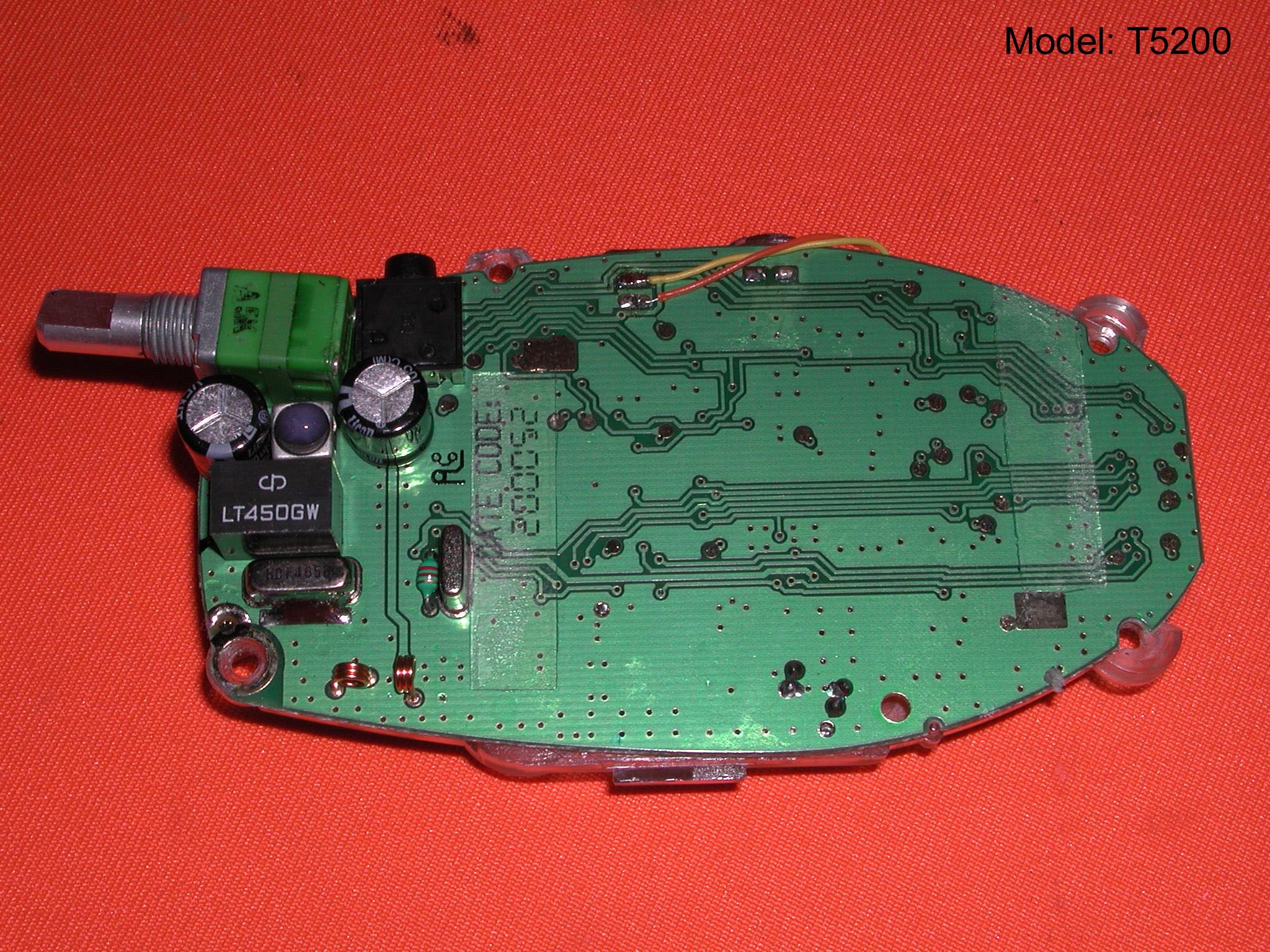
1 OF 3 Circuit Description MODEL T5100/5200 RF I) TX Path 1. The antenna port has given 26 to 27dBm transmitted power and –119dBm sensitivity respectively. 2. There are matching network with TX/RX path switching between the antenna port and PA, it is consist with LC component and pin diode to match the PA to antenna with band pass filtering and isolating TX/RX path. 3. The path switching is consist of D101 and D102, the transmitted power will flow once the dc bias is given to these two diode and there will have 20 dB isolation between TX and RX path. 4. C102, C103, L101, C101 and L105 act as matching network (MN) to match output of PA to be 50 ohm. 5. There have a driver Q103 before the power input to PA from VCO, the power input to driver and PA is 0dBm and +18dBm respectively. 6. L101 and L105 are air coil in order to reduce the power dissipation as high power flowing along this path. 7. There is a single VCO solution, VCO acts as carrier generator (~0dBm) in TX mode and local oscillator (~- 9dBm) in RX mode respectively. 8. The coil L113 acts as variable inductor for VCO voltage tuning. The VCO sensitivity is ~5MHz/V for both in TX mode and RX mode. The D104 acts as switching diode for 21.4MHz band switching. It is turned on in RX mode and off in TX mode by T3V. 9. Twin transistor Q106 is used in VCO, one for VCO and the other for buffer amplifier to give better isolation between VCO and driver amplifier, VCO and the 1 st mixer. 10. The modulated signal feeds from R128 and modulated with D103 11. The loop filter is consist of LC component with 150Hz corner frequency in order to reject the reference frequency 3.125KHz. 12. The feedback frequency from VCO to PLL IC IC102 is filtered with C145 and C149 in order to reject the reference frequency 3.125KHz. 13. Q101 acts as switch for switching the PA, the Q104 is turned on once the PLL is locked in TX mode. 14. Q108 and Q107 act as switch, Q108 and Q107 are turned off in TX mode and inverse in RX mode to give the ground state to the band switching diode D103. 15. 20.95MHz crystal X101 works with direct compensation circuit to give +/-2.5ppm over -20C to +55C. 16. IC109 acts as voltage regulator to give stable voltage supply to +3V path. THE CONTENT OF THIS DOCUMENT IS GIANT IMTELLECTUAL PROPERTY AND IS THE PROPERTY OF GIANT IS TO BE TREATED AS SRTICTLY AND IS NOT BE DISCLOSED. REPODUCED EXCEPT AS AUTHORIZED IN WRITING BY GIANT ELECTRONIC LTD. IN CONNECTION WITH THE MANUFACTURE,MAINTENANCE AND USE OF THE GIANT WHICH IT PERTAINS. COPY @GIANT ELECT LTD ALL RIGHTS RESERVED. 2 OF 3 II) RX Path 1. C113 and L104 were used to match the antenna to 50 ohm input port of saw filter BPF101, the saw filter is used to attenuate the unwanted signal and 1 st IF image signal. 2. Q102 acts as LNA between SAW filter and 1 st mixer to amplify the wanted signal by 10dB. 3. The dual gate FET Q105 acts as the 1 st mixer. The resultant signal of mixer output is RX - LO, which is equal to the 1 st IF frequency of 21.4MHz. 4. The frequency of 1 st LO is injected from VCO to mixer Q105. L110 and C120 act as matching network to match VCO to mixer input port and give better isolation between them in order to improve the problem of malfunction. 5. Q107 acts as switch to turn on the RX path in RX mode in order to save the power consumption and prevent the noise from audio output of IF IC picked up by transmitted carrier. 6. The 1 st IF crystal filter BPF102 with +/- 3.75KHz bandwidth provide better adjacent selectivity and 2 nd IF image rejection. 7. The FM IF IC IC101 integrate the IF limiter, demodulator, 2 nd mixer and 2 nd local oscillator. 8. The 2 nd LO frequency is generated from the X101. The 2 nd IF filter BPF103 is 450KHz filter with +/-4.5KHz bandwidth (G type) to further enhance the adjacent channel selectivity. 9. Noise detector is used for signal detection which is built with the internal op-amp of IF IC and the level is tuned to 8~12dB SINAD with VR102. BASEBAND (I) TX Path 1. Mic The internal/external mic transfer the sound pressure into electrical signal. About 5mV at 1KHz, when the mic is placed 3 to 4 cm from the lips. This signal will send to the mic amplifier to increase the signal level for compressor IC to process. 2. Mic. Amplifier The IC103D bias as a multi feedback high pass filter with 2-pole has a roll off at about 300Hz to reduce the hum noise. The voltage gain is about 18.3. The output will send to the input of compressor. 3. Compressor The compressor IC105 compress the audio signal to increase the average modulation level. The standard input level (0dB gain) of the compressor is 100mV. The output of compressor will send to next stage for emphasis. 4. Pre-emphasis Pre-emphasis is implement with the IC103C to produce a frequency response of 6dB/octave. This circuit also limit the maximum deviation at 2.5KHz to met the specification (standard deviation ~ 1.5KHz, maximum deviation ~ 2.5KHz). The output will send to next stage for limiting. THE CONTENT OF THIS DOCUMENT IS GIANT IMTELLECTUAL PROPERTY AND IS THE PROPERTY OF GIANT IS TO BE TREATED AS SRTICTLY AND IS NOT BE DISCLOSED. REPODUCED EXCEPT AS AUTHORIZED IN WRITING BY GIANT ELECTRONIC LTD. IN CONNECTION WITH THE 3 OF 3 MANUFACTURE,MAINTENANCE AND USE OF THE GIANT WHICH IT PERTAINS. COPY @GIANT ELECT LTD ALL RIGHTS RESERVED. (II) RX Path 1. De-emphasis The de-emphasis of the demodulated signal from RF section is implemented with CTCSS IC. If CTCSS IC is not used, de-emphasis is implement with the RC network R163 and C182. The RC network has 2-pole with 0dB at 1KHz, 3.5dB at 0.5KHz and –8.5dB at 2.5KHz. 2. Expander The expander IC105 expand the audio signal to reduce the noise level. The standard output level for the expander is 100mV. The output will send to the speaker amplifier through volume control. 3. Volume Control The VR103 (volume control switch) has two function, the ON/OFF switch and speaker volume control. 4. Speaker Amplifier The speaker amplifier IC108 amplify the expander sig…
Text truncated - open the document above for the full version.
RF Exposure Info
Form SAR-Rpt-A Page 1 of 1 Certificate Number: 1449-02 ELECTROMAGNETIC EXPOSURE (EME) TESTING LABORATORY 8000 West Sunrise Blvd. Fort-Lauderdale, Florida S.A.R. TEST REPORT FCC ID: K7GT5X00 T5200– P14TAD03P2AA February 16, 2001 Rev A Tested By: Stephen C. Whalen EME Engineer Prepared By: Stephen C. Whalen EME Engineer Reviewed and Approved By: Ken Enger Sr. Resource Manager Product Safety and EME Lab Director Form SAR-Rpt-A Page 2 of 2 TABLE OF CONTENTS 1.0 Introduction 2.0 Reference Standards and Guidelines 3.0 Description of Test Sample 3.1 Antenna Description 3.1.1 Antenna Type 3.1.2 Antenna Location 3.1.3 Antenna Dimensions 3.1.4 Antenna Configuration 3.1.5 Antenna Gain 3.2 Test Signal 3.3 Test Frequency and Output Power 4.0 Description of Test Equipment 4.1 Description of SAR Measurement System 4.2 Description of Phantom 4.2.1 Full Body Phantom 4.3 Simulated Tissue Properties 4.3.1 Type of Simulated Tissue 4.3.2 Simulated Tissue Composition 5.0 Description of Test Procedure 5.1 Description of Test Positions 5.2 Probe Scan Procedures 6.0 Measurement Uncertainty 7.0 SAR Test Results Form SAR-Rpt-A Page 3 of 3 TABLE OF CONTENTS (Cont.) 8.0 Conclusion Appendix A: Data Results Appendix B: Illustrations of Body-worn Accessories Appendix C: Dipole Validation Data Result Appendix D: Measurement Probe Calibration Certificate REVISION HISTORY Date Revision Comments 02/16/01 O Original 04/11/01 A Corrected date on cover page Form SAR-Rpt-A Page 4 of 4 1.0 Introduction This report details the test setup, test equipment, and test results of the Specific Absorption Rate (SAR) measurement performed at CGISS EME laboratory for the T5200 Portable Radio Product, model number P14TAD03P2AA (FCC ID: K7GT5X00). 2.0 Reference Standards and Guidelines This product is designed to comply with the following national and international standards and guidelines. • United States Federal Communications Commission, Code of Federal Regulations; 47 CFR part 2 sub-part J • American National Standards Institute (ANSI) / Institute of Electrical and Electronic Engineers (IEEE) C95. 1-1992 • Institute of Electrical and Electronic Engineers (IEEE) C95.1-1999 Edition • National Council on Radiation Protection and Measurements (NCRP) of the United States, Report 86, 1986 • International Commission on Non-Ionizing Radiation Protection (ICNIRP) 1998 • Ministry of Health (Canada) Safety Code 6. Limits of Human Exposure to Radiofrequency Electromagnetic Fields in the Frequency Range from 3 kHz to 300 GHz, 1999 • Australian Communications Authority Radiocommunications (Electromagnetic Radiation - Human Exposure) Standard 1999 (applicable to wireless phones only) Form SAR-Rpt-A Page 5 of 5 3.0 Description of Test Sample The Portable Device, Model number P14TAD03P2AA operates in 462.5625 – 467.7125 MHz band at a rated ERP (Effected Radiated Power) of 0.5W as a 2-way PTT (Push-To-Talk) with 14 channels and is marketed for FRS (Family Radio Services). The following antenna, battery, and accessories/options were tested: (Refer to appendix B for illustrations of Body-worn Accessories.) Item Kit Number Description Antenna NA ¼ wave, Helical, Fixed Non-removable Battery AA COTS (Commercial Off The Shelf) Alkaline Carry case NTN9399A Arm Pack/Belt Carry Case NTN9392A Swivel Belt Clip Audio NTN8867A Remote Speaker Microphone NTN8870A Earbud W/PTT Microphone Form SAR-Rpt-A Page 6 of 6 3.1 Antenna Description: 3.1.1 Antenna Location on Device LeftRightX TopX BottomFrontBack 3.1.2 Antenna Dimensions Length - cm 6.5 Diameter - cm (at tip of antenna) 1.1 Diameter - cm (at middle of antenna) 1.4 Diameter - cm (at base of antenna) 1.6 3.1.3 Antenna Configuration FixedX Retractable ExternalX Internal Other 3.1.4 Antenna Gain: Extended -2.0 dBi Retracted NA 3.2 Test Signal Test Signal Source: Test Mode Base Station Simulator Native Transmission Mode X Signal Modulation: CW X TDMA Other Form SAR-Rpt-A Page 7 of 7 3.3 Test Frequency and Output Power Output power measurement conditions: Free Space Radiated SAR test configuration ConductedX Other Output Power measured with: Power meter RF Communications test set HP8920B X Spectrum Analyzer Other Test Frequency (MHz) Initial Measured Power before SAR (W) dB loss from Initial Power after SAR (dB) 467.6875 0.452 -1.0 4.0 Description of Test Equipment 4.1 Descriptions of SAR Measurement System The laboratory utilizes a Dosimetric Assessment System (DASY) SAR measurement system manufactured by Schmid & Partner Engineering AG (SPEAG™), of Zurich Switzerland. The SAR measurements were conducted with the ET3DV6 (serial number 1383) probe. It was calibrated at SPEAG™, and has a calibration date August 30, 2000. A copy of the calibration certificate is included as appendix C. Dipole Validation Kit type 450MHz (serial number 450-002) was used to validate the system accuracy at 450MHz. The Dipole validation result is 4.91mW/g when normalized to 1W compared to the target of 5.16mW/g, which is within the required accuracy of ± 10% (Dipole SAR Validation Certificate for Dipole S/N 450-002), and thus the measured SAR values are considered correct. See appendix B for print out of the validation test results from the DASY measurement system. The DASY system is operated per the instructions in the DASY Users Manual. The entire manual is available directly from SPEAG. 4.2 Description of Phantom Human shaped, solid shell device made of fiberglass and mounted on a nonmetallic base or stand. 4.2.1 Full Body Phantom Abdomen Thickness (mm) 0.15 Form SAR-Rpt-A Page 8 of 8 Face Thickness (mm) 0.15 4.3 Simulated Tissue Properties: 4.3.1 Type of Simulated Tissue Tissue type Full Body Head Muscle X Brain NA 4.3.2 Simulated Tissue Composition Frequency 450MHz Muscle Brain Di-Water 52 % NA Sugar 44.9 % NA Salt 2 % NA HEC 1 % NA Dowicil75 0.1 % NA Note: HEC (HYDROXYETHYL CELLULOSE) is a gelling agent and Dowicil 75 is anti bacterial compound. Characterization of Simulated tissue materials and ambient conditions: Simulated tissue …
Text truncated - open the document above for the full version.
Contact Information
Applicant
Yumin Zou(A. Manager)
Technical Contact
Intertek Testing Services Hong Kong Ltd.Wilson Loke
[email protected](852) 21738575
2/F., Garment Centre, · Kowloon · Hong Kong
Non-Technical Contact
Intertek Testing Services Hong Kong Ltd.Wilson Loke
[email protected](852) 21738575
Test Firm
Intertek Testing Services Hong KongBilly Chow
Technical Specifications
| # | Rule Parts | Frequency Range | Power Output | Emission | Tolerance |
|---|---|---|---|---|---|
| 1 | 95B | 462.5625 MHz - 467.7125 MHz | 460.00 mW | 10K7F3E | 2.5000000000 ppm |
Other Applications from Giant Electronics Ltd

K7GMDBJJPR
Jun 24, 2012Two Way Radio - FRS
Equipment Class
FRF - Part 95 Family Radio Face Held Transmitter
K7GMTCEJ
Apr 26, 2012Two Way Radio with GMRS and FRS
Equipment Class
CXX - Communications Rcvr for use w/ licensed Tx and CBs
K7GMDBJJ
Mar 01, 2012Two Way Radio with GMRS and FRS
Equipment Class
FRF - Part 95 Family Radio Face Held Transmitter
K7GMSFGJ
Mar 10, 2011Two Way Radio with Weather Band
Equipment Class
CXX - Communications Rcvr for use w/ licensed Tx and CBs
K7GT2007
Apr 08, 2010Two Way Radio with GMRS and FRS
Equipment Class
FRF - Part 95 Family Radio Face Held Transmitter