K7GT6500Transmitter Portion of Two Way Radio w/FRS & GMRS
Giant Electronics Ltd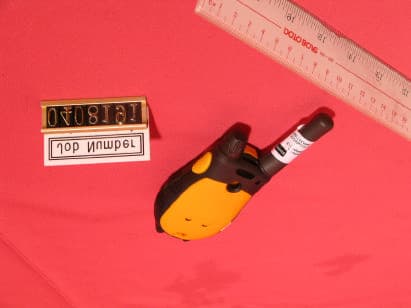
Click to zoom
Application Details
- Equipment Class
- FRF - Part 95 Family Radio Face Held Transmitter
- Date of Grant
- Jun 03, 2004
- Application Purpose
- Original Equipment
- Date of Application
- Jun 03, 2004
- Equipment Note
- Transmitter Portion of Two Way Radio w/FRS & GMRS
- Frequency Range
- 467.56250000 - 467.71250000
- Company
- Giant Electronics Ltd
- Country
- Hong Kong
Documents & Files
Document Text
Text extracted from the exhibit documents filed with the FCC. Open a document above to read the original.
Users Manual
CAUTION:
External Photos
Test Setup FCC ID : K7GT6500 External Photo -front External Photo - rear
Internal Photos
Test Setup FCC ID : K7GT6500 Internal Photo – 1 Internal Photo - 2 Test Setup FCC ID : K7GT6500 Internal Photo - 3 Internal Photo - 4
Parts List/Tune Up Info
THE CONTENT OF THIS DOCUMENT IS GIANT ELCT.LTD. INTELLECTUAL PROPERTY AND IS THE PROPERTY OF GIANT, IT IS TO BE TREATED AS STRICTLY AND IS NOT BE DISCLOSED, REPRODUCED, OR USED EXCEPT AS AUTHORIZED IN WRITING BY GIANT ELECTRONIC LTD. IN CONNECTION WITH THE MANUFACTURE,MAINTENANCE AND USE OF THE GIANT EQUIPMENT WHICH IT PERTAINS. COPYRIGHT @GIANT ELECT. LTD, ALL RIGHTS RESERVED. GIANT ELECTRONICS LTD. Title: Alignment Procedure Model: T6500 A. PCB LEVEL (Test Condition: under CH15) NO ITEM ALIGNMENT METHOD REMARK 1. LCD display (Should enter test mode) 1. Press and hold the ‘+’ key and ‘Menu’ key together. 2. Turn on the radio power until a good key chirp is heard, and the backlight is on for about 500 ms . finally, the LCD should be display ‘ 1 CH ’. 3. Press ‘DOWN’ key , then all LCD segments should be anticlockwise displayed. 4. Finally, all the LCD segments should be shown for about 500ms as follows: 2 18 88. . 2. Standby current 1. Set A-METER, and RX mode. 2. Check the standby current <45mA DC. 3. Talk on current 1. Set A-METER, and TX mode @50ohm load. 2. Check the talk on current <900mA DC. 3. Set channel to 14 4. Check the talk on current <500mA DC. 4. VCO 1. Set RX or TX mode 2. Check TP503 to provide 0.7~2.3VDC . 3. Adjust L509 to provide 2.2 0.1 VDC at TP503 if VCO level are more than 2.4VDC on CH14. 4. Set WX mode, check TP504 to provide 0.7~2.4VDC(for T5950) 5. TX Power 1. Set TX mode CH15, Check transmit power to provide <GMRS 2. Set TX mode CH14, Adjust VR503 to provide <FRS 6. TX Frequency 1. Set TX mode 2. Adjust VC501 to provide 462.5500MHz ± 50Hz. 7. CTCSS Tone Frequency 1. Set CH15/CODE1 and Tx mode. 2. Check CTCSS tone frequency to be within 66.8Hz to 67.2Hz. 8. CDCSS Frequency 1. Set TX mode 2. Set CH15/CODE99 3. Adjust VR501 to provide 503 Octal Code 4. Set CH15/CODE39, check Octal Code to be 023 FILTER SET: 1.Input Level: 0.9KHz 9. CTCSS Tone Dev. 1. Set CH15/CODE1 AF input level to off, check DEV to be 300Hz~ 650Hz. 2. Set CH14/CODE38 AF input level to off, check DEV to be 300Hz~ 650Hz. FILTER SET: 1.50HZ~300HZ 2.750μs De-emp ON 3. PK+ 4. FM DEV. AVG ON 10. TX Modulation & distortion 1.Set AF level at 50mv;1KHz,Adjust VR101 to provide Max TX deviation 2.25KHz to 2.35KHz. 2.Check input Mic level in 5~15 mV to provide normal deviation 1.5KHz. 3.Check the demodulation distortion <= 5%. 5. Audio Frequency Response. a) Input a 2.0mV 1KHz audio frequency to TP116 and press ‘PTT’ switch. b) Check the response compare to 1KHz tone. i) 500Hz : -5.0 dB to –11.0 dB. ii) 2.5KHz : +3.0 dB to +9.0 dB . FILTER SET: 1.HPF 50Hz 2.LPF 15KHz 3. PK + THE CONTENT OF THIS DOCUMENT IS GIANT ELCT.LTD. INTELLECTUAL PROPERTY AND IS THE PROPERTY OF GIANT, IT IS TO BE TREATED AS STRICTLY AND IS NOT BE DISCLOSED, REPRODUCED, OR USED EXCEPT AS AUTHORIZED IN WRITING BY GIANT ELECTRONIC LTD. IN CONNECTION WITH THE MANUFACTURE,MAINTENANCE AND USE OF THE GIANT EQUIPMENT WHICH IT PERTAINS. COPYRIGHT @GIANT ELECT. LTD, ALL RIGHTS RESERVED. GIANT ELECTRONICS LTD. Title: Alignment Procedure Model: T6500 A. PCB LEVEL (Test Condition: under CH15) NO ITEM ALIGNMENT METHOD REMARK 11. VOX Detector 1. Set VOX level at 1. 2. Set AF level at 14.2 +/- 0.2 mV,1KHz at TP116. 3. Unit start to transmit. 4. Set AF level at 10.8 +/- 0.2mV,1KHz at TP116. 5. Unit stop transmit. 6. Set VOX level at 2. 7. Set AF level at 8.4 +/- 0.2mV,1KHz at TP116. 8. Unit start to transmit. 9. Set AF level at 5.8 +/- 0.2mV,1KHz at TP116. 10. Unit stop transmit. 11. Set VOX level at 3 12. Set AF level at 4.0 +/- 0.2mV,1KHz at TP116. 13. Unit start to transmit. 14. Set AF level at 2.7 +/- 0.2mV,1KHz at TP116. 15. Unit stop transmit. 12. IVOX Detector 1. Set VOX level at 1. 2. Set AF level at 14.2 +/- 0.2 mV,1KHz at TP116. 3. Unit start to transmit. 4. Set AF level at 10.8 +/- 0.2mV,1KHz at TP116. 5. Unit stop transmit. 6. Set VOX level at 2. 7. Set AF level at 8.4 +/- 0.2mV,1KHz at TP116. 8. Unit start to transmit. 9. Set AF level at 5.8 +/- 0.2mV,1KHz at TP116. 10. Unit stop transmit. 11. Set VOX level at 3 12. Set AF level at 4.0 +/- 0.2mV,1KHz at TP116. 13. Unit start to transmit. 14. Set AF level at 2.7 +/- 0.2mV,1KHz at TP116. 15. Unit stop transmit 13. Rx Audio test 1. Set RX mode CH7. 2. Set SG RF level to –50dBm with 1.5KHz deviation 1KHz modulation Signal. 3. Adjust L517 to provide minimum distortion & max output level at TP117. 4. Rotate the volume switch to the position, which give a Max audio output at TP117. 5. Check Max audio output level >1500mV. 6. Check Rx current <150mA. 7. Check the 1KHz distortion <= 5%. 8. Set SG RF level to –119dBm with 1.5kHz deviation at 1KHz audio frequency. a). Check SINAD sensitivity <= -119dBm. @12dB SINAD at TP117. THE CONTENT OF THIS DOCUMENT IS GIANT ELCT.LTD. INTELLECTUAL PROPERTY AND IS THE PROPERTY OF GIANT, IT IS TO BE TREATED AS STRICTLY AND IS NOT BE DISCLOSED, REPRODUCED, OR USED EXCEPT AS AUTHORIZED IN WRITING BY GIANT ELECTRONIC LTD. IN CONNECTION WITH THE MANUFACTURE,MAINTENANCE AND USE OF THE GIANT EQUIPMENT WHICH IT PERTAINS. COPYRIGHT @GIANT ELECT. LTD, ALL RIGHTS RESERVED. GIANT ELECTRONICS LTD. Title: Alignment Procedure Model: T6500 A. PCB LEVEL (Test Condition: under CH15) NO ITEM ALIGNMENT METHOD REMARK 9. Audio frequency response. a) Set SG RF level to –50dBm with 1.5kHz deviation at 1KHz audio frequency. b) Rotate the volume switch to the position, which give an output 100mV 5mV at TP117. c) Vary the audio frequency from 300Hz to 3KHz. d) Check the RX response compare to 1KHz tone. i) 500Hz : +5.0 dB to +14.0 dB. ii) 2.5KHz : -12.0 dB to –20.0 dB 10. Maximum and Minimum Audio Output Power. a) Set SG RF level to –50dBm with 1.5kHz deviation at 1KHz audio frequency. b) Rotate the volume switch to the position, which give a maximum output . c) Check the voltage at TP117 >/=1500mV. d) Set maximum audio output to 0dB, rotate the volume switch to the position, which give a minimum output. e) Check the minimum voltage -23dB to -40dB at TP117 11. Set WX mode, Set SG RF level t…
Text truncated - open the document above for the full version.
RF Exposure Info
© 2004 Celltech Labs Inc. 1 of 20 Test Report S/N: 041504-500K7G Test Date(s): April 19-20, 2004 Test Type: FCC/IC SAR Evaluation Celltech Labs Inc. declares under its sole responsibility that this wireless portable device has demonstrated compliance with the Specific Absorption Rate (SAR) RF exposure requirements specified in FCC 47 CFR §2.1093 and Health Canada’s Safety Code 6. The device was tested in accordance with the measurement standards and procedures specified in FCC OET Bulletin 65, Supplement C (Edition 01-01) and Industry Canada RSS-102 Issue 1 (Provisional) for the General Population / Uncontrolled Exposure environment. All measurements were performed in accordance with the SAR system manufacturer recommendations. I attest to the accuracy of data. All measurements were performed by me or were made under my supervision and are correct to the best of my knowledge and belief. I assume full responsibility for the completeness of these measurements and vouch for the qualifications of all persons taking them. This test report shall not be reproduced partially, or in full, without the prior written approval of Celltech Labs Inc. The results and statements contained in this report pertain only to the device(s) evaluated. Russell W. Pipe Senior Compliance Technologist Celltech Labs Inc. DECLARATION OF COMPLIANCE SAR RF EXPOSURE EVALUATION Test Lab CELLTECH LABS INC. Testing and Engineering Services 1955 Moss Court Kelowna, B.C. Canada V1Y 9L3 Phone: 250-448-7047 Fax: 250-448-7046 e-mail: [email protected] web site: www.celltechlabs.com Applicant Information GIANT ELECTRONICS LTD. 7/F, Elite Industrial Bldg. 135-137 Hoi Bun Road Kwun Tong, Kowloon Hong Kong Rule Part(s): FCC 47 CFR §2.1093; IC RSS-102 Issue 1 (Provisional) Test Procedure(s): FCC OET Bulletin 65, Supplement C (Edition 01-01) Device Type: Portable UHF FRS/GMRS PTT Radio Transceiver FCC IDENTIFIER: K7GT6500 Model(s): T6500 / T6550 Modulation: FM (UHF) Tx Frequency Range(s): 462.5500 - 462.7250 MHz (GMRS Channels 15-22) 462.5625 - 462.7125 MHz (FRS/GMRS Channels 1-7) 467.5625 - 467.7125 MHz (FRS Channels 8-14) RF Output Power Tested: 0.581 Watts ERP (GMRS 462.7125 MHz) Antenna Type(s) Tested: Fixed Battery Type(s) Tested: NiCd (3.6 V, 600 mAh), Alkaline x3 (1.5 V AA) Alkaline Type 1: Duracell Procell (2850 mAh) Alkaline Type 2: Energizer E91 (2850 mAh) Body-Worn Accessories Tested: Plastic Swivel Belt-Clip (P/N: NTN9392B) Earbud with Lapel-Microphone (P/N: NTN8870C) Earpiece with Boom-Microphone (P/N: NTN9396BW) Headset with Boom-Microphone (P/N: NTN8868B) Maximum SAR Levels Measured: 0.938 W/kg - Face-held (50% duty cycle) 1.08 W/kg - Body-worn (50% duty cycle) © 2004 Celltech Labs Inc. 2 of 20 Test Report S/N: 041504-500K7G Test Date(s): April 19-20, 2004 Test Type: FCC/IC SAR Evaluation TABLE OF CONTENTS 1.0INTRODUCTION.....................................................................3 2.0DESCRIPTION OF DUT............................................................ 3 3.0SAR MEASUREMENT SYSTEM................................................ 4 4.0MEASUREMENT SUMMARY..................................................... 5 5.0DETAILS OF SAR EVALUATION............................................... 6 6.0EVALUATION PROCEDURES................................................... 6 7.0SYSTEM PERFORMANCE CHECK............................................. 7 8.0SIMULATED EQUIVALENT TISSUES......................................... 8 9.0SAR SAFETY LIMITS............................................................... 8 10.0ROBOT SYSTEM SPECIFICATIONS........................................... 9 11.0PROBE SPECIFICATION.......................................................... 10 12.0PLANAR PHANTOM................................................................ 10 13.0VALIDATION PHANTOM........................................................... 10 14.0DEVICE HOLDER.................................................................... 10 15.0TEST EQUIPMENT LIST........................................................... 11 16.0MEASUREMENT UNCERTAINTIES............................................ 12-13 17.0REFERENCES........................................................................14 APPENDIX A - SAR MEASUREMENT DATA............................................... 15 APPENDIX B - SYSTEM PERFORMANCE CHECK DATA............................ 16 APPENDIX C - SYSTEM VALIDATION PROCEDURES................................. 17 APPENDIX D - PROBE CALIBRATION...................................................... 18 APPENDIX E - MEASURED FLUID DIELECTRIC PARAMETERS................... 19 APPENDIX F - SAR TEST SETUP & DUT PHOTOGRAPHS.......................... 20 © 2004 Celltech Labs Inc. Giant Electronics Ltd. FCC ID: K7GT6500 (Models: T6500/T6550) 3 of 20 Portable UHF FRS/GMRS PTT Radio Transceiver (462.5500-467.7125MHz) Test Report S/N: 041504-500K7G Test Date(s): April 19-20, 2004 Test Type: FCC/IC SAR Evaluation This measurement report demonstrates compliance of the Giant Electronics Ltd. Models: T6500/T6550 Portable UHF FRS/GMRS PTT Radio Transceiver FCC ID: K7GT6500 with the SAR (Specific Absorption Rate) RF exposure requirements specified in FCC 47 CFR §2.1093 (see reference [1]), and Health Canada’s Safety Code 6 (see reference [2]) for the General Population / Uncontrolled Exposure environment. The test procedures described in FCC OET Bulletin 65, Supplement C (Edition 01-01) (see reference [3]) and IC RSS-102 Issue 1 (Provisional) (see reference [4]), were employed. A description of the product and operating configuration, detailed summary of the test results, methodology and procedures used in the evaluation, equipment used, and the provisions of the rules are included within this test report. FCC 47 CFR §2.1093 Rule Part(s) IC RSS-102 Issue 1 (Provisional) Test Procedure FCC OET Bulletin 65, Supplement C (01-01) Device Type Portable UHF FRS/GMRS PTT Radio Transceiver FCC IDENTIFIER K7GT6500 Model(s) T6500 / T6550 Serial No. # 1 (Pro…
Text truncated - open the document above for the full version.
Test Setup Photos
Test Setup FCC ID: K7GT6500 Radiated -front Radiated - rear
Contact Information
Applicant
Yumin Zou(A. Manager)
Technical Contact
Intertek Testing Services Hong Kong Ltd.Tommy Leung
[email protected]852 2173 8538
2/F., Garment Centre · Kowloon · Hong Kong
Non-Technical Contact
Intertek Testing Services Hong Kong Ltd.Tommy Leung
[email protected]852 2173 8538
Test Firm
Intertek Testing Services Hong KongC. Yuen
Technical Specifications
| # | Rule Parts | Frequency Range | Power Output | Emission | Tolerance |
|---|---|---|---|---|---|
| 2 | 95B | 467.5625 MHz - 467.7125 MHz | 400.00 mW | 10K3F3E | 1.71 ppm |
Other Applications from Giant Electronics Ltd

K7GMDBJJPR
Jun 24, 2012Two Way Radio - FRS
Equipment Class
FRF - Part 95 Family Radio Face Held Transmitter
K7GMTCEJ
Apr 26, 2012Two Way Radio with GMRS and FRS
Equipment Class
CXX - Communications Rcvr for use w/ licensed Tx and CBs
K7GMDBJJ
Mar 01, 2012Two Way Radio with GMRS and FRS
Equipment Class
FRF - Part 95 Family Radio Face Held Transmitter
K7GMSFGJ
Mar 10, 2011Two Way Radio with Weather Band
Equipment Class
CXX - Communications Rcvr for use w/ licensed Tx and CBs
K7GT2007
Apr 08, 2010Two Way Radio with GMRS and FRS
Equipment Class
FRF - Part 95 Family Radio Face Held Transmitter