K7GT6525Two Way Radio with FRS
Giant Electronics Ltd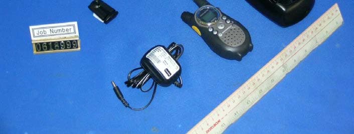
Click to zoom
Application Details
- Equipment Class
- FRF - Part 95 Family Radio Face Held Transmitter
- Date of Grant
- Oct 20, 2006
- Application Purpose
- Original Equipment
- Date of Application
- Oct 20, 2006
- Equipment Note
- Two Way Radio with FRS
- Frequency Range
- 467.56250000 - 467.71250000
- Company
- Giant Electronics Ltd
- Country
- Hong Kong
Documents & Files
Document Text
Text extracted from the exhibit documents filed with the FCC. Open a document above to read the original.
Users Manual
1 of 12 T6525 14 NiMH 2 of 12 3 of 12 4 of 12 5 of 12 This device complies with Part 15 of the FCC Rules. Operation is subject to the following two conditions: 1 . This device may not cause harmful interference, and 2 . This device must accept any interference received, including interference that may cause undesired operation. 6 of 12 NiMH NiMH NiMH T6525 NiMH NiMH NiMH 7 of 12 Note z The light on charging base will glow continuously when radio/battery is inserted. z When moving between hot and cold temperature, do not charge the battery until the battery temperature acclimates (usually about 20 minutes). z For optimal battery life, remove the radio or battery from the charger within 16 hours. Do not store the radio in the charger. z Turn off the radio while in the charging tray. NiMH NiMH NiMH 8 of 12 Channel Frequency Channel Frequency 1 462.5625 MHz 8 467.5625 MHz 2 462.5875 MHz 9 467.5875 MHz 3 462.6125 MHz 10 467.6125 MHz 4 462.6375 MHz 11 467.6375 MHz 5 462.6625 MHz 12 467.6625 MHz 6 462.6875 MHz 13 467.6875 MHz 7 462.7125 MHz 14 467.7125 MHz And all are FRS (1-14) 14 When the radio is on the transmitting, the display have . And all are FRS. 14 9 of 12 10 of 12 11 of 12 12 of 12
Cover Letter(s)
The content of this document is Giant Electronics Ltd.'s intellectual property and is the property of Giant. It is to be treated as strictly confidential and is not to be disclosed, reproduced, or used except as authorized in writing by Giant Electronics Ltd. In connection with the manufacture, maintenance and use of the Giant equipment to which it pertains. Copyright @Giant Electronics Ltd. All rights reserved. Re: FCC ID: K7GT6525 Pursuant to 47 CFR 0.459, Giant Electronics Ltd. request confidential protection of the following documents submitted electronically in furtherance of the above-reference application as containing propriety information listed below: ■ Schematic ■ Block Diagram ■ Operational Description This information represents intellectual property of Giant Electronics Ltd. and it is subject to competition. This information should not be made routinely available for public inspection, and Giant Electronics Ltd. reserves the right to discern which parties can obtain access to this information. Dated this 12 th day of May 2006 By: YK Ling . Signature Printed Title : Electronic Engineer Confidentiality Request Letter
External Photos
INTERTEK TESTING SERVICES External Photos FCC ID: K7GT6525 external photos - 1 of 1 External Photo - Front External Photo - Rear
Internal Photos
INTERTEK TESTING SERVICES Internal photos FCC ID: K7GT6525 internal photos - 1 of 3 Internal Photo - 1 Internal Photo - 2 INTERTEK TESTING SERVICES Internal photos FCC ID: K7GT6525 internal photos - 2 of 3 Internal Photo - 3 Internal Photo - 4 INTERTEK TESTING SERVICES Internal photos FCC ID: K7GT6525 internal photos - 3 of 3 Internal Photo - 5
Parts List/Tune Up Info
Giant Electronics Ltd. T6525 BOM...T6525 BOM 2006-7-28 1 // 8 Giant Electronics Ltd. T6525 BOM...T6525 BOM 2006-7-28 2 // 8 Giant Electronics Ltd. T6525 BOM...T6525 BOM 2006-7-28 3 // 8 Giant Electronics Ltd. T6525 BOM...T6525 BOM 2006-7-28 4 // 8 Giant Electronics Ltd. T6525 BOM...T6525 BOM 2006-7-28 5 // 8 Giant Electronics Ltd. T6525 BOM...T6525 BOM 2006-7-28 6 // 8 Giant Electronics Ltd. T6525 BOM...T6525 BOM 2006-7-28 7 // 8 Giant Electronics Ltd. T6525 BOM...T6525 BOM 2006-7-28 8 // 8
Parts List/Tune Up Info
THE CONTENT OF THIS DOCUMENT IS GIANT ELCT.LTD. INTELLECTUAL PROPERTY AND IS THE PROPERTY OF GIANT, IT IS TO BE TREATED AS STRICTLY AND IS NOT BE DISCLOSED, REPRODUCED, OR USED EXCEPT AS AUTHORIZED IN WRITING BY GIANT ELECTRONIC LTD. IN CONNECTION WITH THE MANUFACTURE,MAINTENANCE AND USE OF THE GIANT EQUIPMENT WHICH IT PERTAINS. COPYRIGHT @GIANT ELECT. LTD, ALL RIGHTS RESERVED. 22Aug06_T6525 ali 060821 revised.doc Page 1 of 7 GIANT ELECTRONICS LTD. Title: Alignment Procedure Model: T6525 A. PCB LEVEL (Test Condition: under CH14) NO ITEM ALIGNMENT METHOD REMARK 1. LCD display (Should enter test mode) 1. Press and hold the ‘+’ key and ‘Menu’ key together. 2. Turn on the radio power until a good key chirp is heard, and the backlight is on for about 500 ms . finally, the LCD should be display ‘1 CH ’. 3. Press ‘DOWN’ key , then all LCD segments should be anticlockwise displayed. 4. Finally, all the LCD segments should be shown for about 500ms as follows: 218 88. . 2. Standby current 1. Set A-METER, and RX mode. 2. Check the standby current <45mA DC. 3. Talk on current 1. Set A-METER, and TX mode @50ohm load. 2. Check the talk on current <550mA DC. 4. VCO 1. Set RX or TX mode 2. Check TP503 to provide 0.6~2.3VDC . 3. Adjust L509 to provide 2.2 ± 0.1VDC at TP503 if VCO level are more than 2.4VDC on CH14. 5. TX Power 1. Set TX mode CH14, Check transmit power to provide 23.2dBm ERP Test voltage DC:4.5V 6. TX Frequency 1. Set TX mode 2. Adjust VC501 to provide 467.7125MHz ± 50Hz. 7. CTCSS Tone Frequency 1. Set CH14/CODE1 and Tx mode. 2. Check CTCSS tone frequency to be within 66.8Hz to 67.2Hz. 8. CDCSS Frequency 1. Set TX mode 2. Set CH14/CODE99 3. Adjust VR501 to provide 503 Octal Code 4. Set CH14/CODE39, check Octal Code to be 023 FILTER SET: 1.Input Level: 0.9KHz 9. CTCSS Tone Dev. 1. Set CH14/CODE1、AF input level to off, check DEV to be 300Hz~ 650Hz. 2. Set CH14/CODE38、AF input level to off, check DEV to be 300Hz~ 650Hz. FILTER SET: 1.50HZ~300HZ 2.750μs De-emp ON 3. PK+ 4. FM DEV. AVG ON 10. TX Modulation & distortion 1.Set AF level at 50mv;1KHz,Adjust VR101 to provide Max TX deviation 2.25KHz to 2.35KHz. 2.Check input Mic level in 5~15 mV to provide normal deviation 1.5KHz. 3.Check the demodulation distortion <= 5%. 5. Audio Frequency Response. a) Input a 2.0mV 1KHz audio frequency to TP116 and press ‘PTT’ switch. b) Check the response compare to 1KHz tone. i) 500Hz : -5.0 dB to –11.0 dB. ii) 2.5KHz : +3.0 dB to +9.0 dB . FILTER SET: 1.HPF 50Hz 2.LPF 15KHz 3. PK + THE CONTENT OF THIS DOCUMENT IS GIANT ELCT.LTD. INTELLECTUAL PROPERTY AND IS THE PROPERTY OF GIANT, IT IS TO BE TREATED AS STRICTLY AND IS NOT BE DISCLOSED, REPRODUCED, OR USED EXCEPT AS AUTHORIZED IN WRITING BY GIANT ELECTRONIC LTD. IN CONNECTION WITH THE MANUFACTURE,MAINTENANCE AND USE OF THE GIANT EQUIPMENT WHICH IT PERTAINS. COPYRIGHT @GIANT ELECT. LTD, ALL RIGHTS RESERVED. 22Aug06_T6525 ali 060821 revised.doc Page 2 of 7 GIANT ELECTRONICS LTD. Title: Alignment Procedure Model: T6525 A. PCB LEVEL (Test Condition: under CH14) NO ITEM ALIGNMENT METHOD REMARK 11. VOX Detector 1. Set VOX level at 1. 2. Set AF level at 14.2 +/- 0.2 mV,1KHz at TP116. 3. Unit start to transmit. 4. Set AF level at 10.8 +/- 0.2mV,1KHz at TP116. 5. Unit stop transmit. 6. Set VOX level at 2. 7. Set AF level at 8.4 +/- 0.2mV,1KHz at TP116. 8. Unit start to transmit. 9. Set AF level at 5.8 +/- 0.2mV,1KHz at TP116. 10. Unit stop transmit. 11. Set VOX level at 3 12. Set AF level at 4.0 +/- 0.2mV,1KHz at TP116. 13. Unit start to transmit. 14. Set AF level at 2.7 +/- 0.2mV,1KHz at TP116. 15. Unit stop transmit. 12. IVOX Detector 1. Set VOX level at 1. 2. Set AF level at 14.2 +/- 0.2 mV,1KHz at TP116. 3. Unit start to transmit. 4. Set AF level at 10.8 +/- 0.2mV,1KHz at TP116. 5. Unit stop transmit. 6. Set VOX level at 2. 7. Set AF level at 8.4 +/- 0.2mV,1KHz at TP116. 8. Unit start to transmit. 9. Set AF level at 5.8 +/- 0.2mV,1KHz at TP116. 10. Unit stop transmit. 11. Set VOX level at 3 12. Set AF level at 4.0 +/- 0.2mV,1KHz at TP116. 13. Unit start to transmit. 14. Set AF level at 2.7 +/- 0.2mV,1KHz at TP116. 15. Unit stop transmit 13. Rx Audio test 1. Set RX mode CH7. 2. Set SG RF level to –50dBm with 1.5KHz deviation 1KHz modulation Signal. 3. Adjust L517 to provide minimum distortion & max output level at TP117. 4. Rotate the volume switch to the position, which give a Max audio output at TP117. 5. Check Max audio output level >1500mV. 6. Check Rx current <150mA. 7. Check the 1KHz distortion <= 5%. 8. Set SG RF level to –119dBm with 1.5kHz deviation at 1KHz audio frequency. a). Check SINAD sensitivity <= -119dBm. @12dB SINAD at TP117. THE CONTENT OF THIS DOCUMENT IS GIANT ELCT.LTD. INTELLECTUAL PROPERTY AND IS THE PROPERTY OF GIANT, IT IS TO BE TREATED AS STRICTLY AND IS NOT BE DISCLOSED, REPRODUCED, OR USED EXCEPT AS AUTHORIZED IN WRITING BY GIANT ELECTRONIC LTD. IN CONNECTION WITH THE MANUFACTURE,MAINTENANCE AND USE OF THE GIANT EQUIPMENT WHICH IT PERTAINS. COPYRIGHT @GIANT ELECT. LTD, ALL RIGHTS RESERVED. 22Aug06_T6525 ali 060821 revised.doc Page 3 of 7 GIANT ELECTRONICS LTD. Title: Alignment Procedure Model: T6525 A. PCB LEVEL (Test Condition: under CH14) NO ITEM ALIGNMENT METHOD REMARK 9. Audio frequency response. a) Set SG RF level to –50dBm with 1.5kHz deviation at 1KHz audio frequency. b) Rotate the volume switch to the position, which give an output 100mV±5mV at TP117. c) Vary the audio frequency from 300Hz to 3KHz. d) Check the RX response compare to 1KHz tone. i) 700Hz : -2 dB to -12.0 dB. ii) 2.0KHz : -15.0 dB to –25.0 dB 10. Maximum and Minimum Audio Output Power. a) Set SG RF level to –50dBm with 1.5kHz deviation at 1KHz audio frequency. b) Rotate the volume switch to the position, which give a maximum output . c) Check the voltage at TP117 >/=1500mV. d) Set maximum audio output to 0dB, rotate the volume switch to the position, which give a minimum output. e) Check the minimum voltage -21dB to -40dB at TP117 11. Set WX mode, Set SG RF level to…
Text truncated - open the document above for the full version.
Test Report
INTERTEK TESTING SERVICES A udio Low Pass Filter Response -70.0-60.0-50.0-40.0-30.0-20.0-10.0 0.0 10.0 1 10 100 Frequency (kHz) dB relative to 1 kHz LPF ResponseTIA/EIA-603B Audio Input Strength = 50mVrms FCC ID : K7GT6525 lpf - 1 of 1
Test Report
INTERTEK TESTING SERVICES Modulation Frequency Response 0.0000.5001.0001.5002.0002.500 200 700 1200 1700 2200 2700 3200 3700 4200 4700 Modulation Frequency (Hz) Frequency Deviation (kHz) FCC ID : K7GT6525 mfr - 1 of 2 INTERTEK TESTING SERVICES Modulation Frequency Response 0.000.501.001.502.002.503.00 300 800 1300 1800 2300 2800 3300 3800 4300 4800 Modulation Frequency (Hz) Modulation Index (%) FCC ID: K7GT6525 mfr - 2 of 2
Test Report
INTERTEK TESTING SERVICES Modulation Limiting Characteristic 0.0000.5001.0001.5002.0002.500 47 57 67 77 87 97 107 117 127 137 Modulation Input (dBSPL) Frequency Deviation (kHz) 500Hz1000Hz2500Hz3125Hz FCC ID : K7GT6525 mlc - 1 of 1
Test Setup Photos
INTERTEK TESTING SERVICES The Worst Case Configuration Photographs FCC ID: K7GT6525 config photos (radiated emission) - 1 of 1 Radiated Emission Front View Rear View
Contact Information
Applicant
Yumin Zou(A. Manager)
Technical Contact
Intertek Testing Services Hong Kong Ltd.Kenneth Lam
[email protected]852-2173-8474
2/F., Garment Centre, · Kowloon · Hong Kong
Non-Technical Contact
Intertek Testing Services Hong Kong Ltd.Kenneth Lam
[email protected]852-2173-8474
Test Firm
Intertek Testing Services Hong KongBilly Chow
Technical Specifications
| # | Rule Parts | Frequency Range | Power Output | Emission | Tolerance |
|---|---|---|---|---|---|
| 2 | 95B | 467.5625 MHz - 467.7125 MHz | 210.00 mW | 5K70F3E | 2.42 ppm |
Other Applications from Giant Electronics Ltd

K7GMDBJJPR
Jun 24, 2012Two Way Radio - FRS
Equipment Class
FRF - Part 95 Family Radio Face Held Transmitter
K7GMTCEJ
Apr 26, 2012Two Way Radio with GMRS and FRS
Equipment Class
CXX - Communications Rcvr for use w/ licensed Tx and CBs
K7GMDBJJ
Mar 01, 2012Two Way Radio with GMRS and FRS
Equipment Class
FRF - Part 95 Family Radio Face Held Transmitter
K7GMSFGJ
Mar 10, 2011Two Way Radio with Weather Band
Equipment Class
CXX - Communications Rcvr for use w/ licensed Tx and CBs
K7GT2007
Apr 08, 2010Two Way Radio with GMRS and FRS
Equipment Class
FRF - Part 95 Family Radio Face Held Transmitter