K7GT8220FRS/GMRS Two Way Radio
Giant Electronics Ltd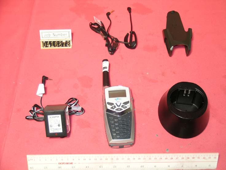
Click to zoom
Application Details
- Equipment Class
- FRF - Part 95 Family Radio Face Held Transmitter
- Date of Grant
- Nov 28, 2004
- Application Purpose
- Original Equipment
- Date of Application
- Nov 28, 2004
- Equipment Note
- FRS/GMRS Two Way Radio
- Frequency Range
- 467.56250000 - 467.71250000
- Company
- Giant Electronics Ltd
- Country
- Hong Kong
Documents & Files
Document Text
Text extracted from the exhibit documents filed with the FCC. Open a document above to read the original.
Users Manual
Safety and General Information Important Information on Safe and Efficient Operation Read This Information Before Using Your Radio The information provided in this document supersedes the general safety information in user guides published prior to December 1, 2002. Transmit and Receive Procedure Your two-way radio contains a transmitter and a receiver. To control your exposure and ensure compliance with the general population/uncontrolled environment exposure limits, always adhere to the following procedure: z Transmit no more than 50% of the time. z To transmit (talk), press the Push to Talk (PTT) button. z To receive calls, release the PTT button. Transmitting 50% of the time, or less, is important because the radio generates measurable RF energy exposure only when transmitting (in terms of measuring standards compliance). Exposure To Radio Frequency Energy Your Our two-way radio complies with the following RF energy exposure standards and guidelines: z United States Federal Communications Commission, Code of Federal Regulations; 47CFR part 2 sub-part J z American National Standards Institute (ANSI) / Institute of Electrical and Electronic Engineers (IEEE) C95. 1-1992 z Institute of Electrical and Electronic Engineers (IEEE) C95. 1-1999 Edition z International Commission on Non-Ionizing Radiation Protection (ICNIRP) 1998 z Ministry of Health (Canada) Safety Code 6. Limits of Human Exposure to Radio frequency Electromagnetic Fields in the Frequency Range from 3 KHz to 300 GHz, 1999 z Australian Communications Authority Radio communications (Electromagnetic Radiation – Human Exposure) Standard, 2003 z ANATEL ANNEX to Resolution No. 303 of July 2, 2002 “Regulation of limitation of exposure to electrical, magnetic and electromagnetic fields in the radio frequency range between 9KHz and 300GHz” and “Attachment to resolution #303 from July 2, 2002” To assure optimal radio performance and make sure human exposure to radio frequency electromagnetic energy is within the guidelines set forth in the above standards, always adhere to the following procedures. The content of this document is Giant Electronics Ltd.'s intellectual property and is the property of Giant. It is to be treated as strictly confidential and is not to be disclosed, reproduced, or used except as authorized in writing by Giant Electronics Ltd. In connection with the manufacture, maintenance and use of the Giant equipment to which it pertains. Copyright @Giant Electronics Ltd. All rights reserved. Page 1 of 12 Portable Radio Operation and EME Exposure Antenna Care Use only the supplied or an approved replacement antenna. Unauthorized antennas, modifications, or attachments could damage the radio and may violate FCC regulations. DO NOT hold the antenna when the radio is “IN USE”. Holding the antenna affects the effective range. Two-way Radio Operatio n When using your radio as a traditional two-way radio, hold the radio in a vertical position with the microphone 1 to 2 inches (2.5 – 5 cm) away from the lips. Body-Worn Operation To maintain compliance with FCC/Health Canada RF exposure guidelines, if you wear a radio on your body when transmitter, always place the radio in a Our supplied or approved clip, holder, holster, case, or body harness for this product. Use of non-Our- approved accessories may exceed FCC/Health Canada RF exposure guidelines. If you do not use one of the our-supplied or approved body-wore accessories, and are not using the radio held in the normal use position, ensure the radio and its antenna are at least 1 inch (2.5 cm) from your body when transmitting. Data Operation If applicable, when using any data feature of the radio with or without an accessory cable, position the radio and its antenna at least 1 inch (2.5 cm) from the body. Electromagnetic Interference/Compatibility Note: Nearly every electronic device is susceptible to electromagnetic interference (EMI) if inadequately shielded, designed, or otherwise configured for electromagnetic compatibility. Facilities To avoid electromagnetic interference and/or compatibility conflicts, turn off your radio in any facility where posted notices instruct you to do so. Hospitals or health care facilities may be using equipment that is sensitive to external RF energy. Aircraft When instructed to do so, turn off your radio when on board an aircraft. Any use of a radio must be in accordance with applicable regulations per airline crew instructions. The content of this document is Giant Electronics Ltd.'s intellectual property and is the property of Giant. It is to be treated as strictly confidential and is not to be disclosed, reproduced, or used except as authorized in writing by Giant Electronics Ltd. In connection with the manufacture, maintenance and use of the Giant equipment to which it pertains. Copyright @Giant Electronics Ltd. All rights reserved. Page 2 of 12 Medical Devices - Pacemakers The advanced Medical Technology Association recommends that a minimum separation of 6 inches (15 cm) be maintained between a handheld wireless radio and a pacemaker. These recommendations are consistent with the independent research by, and recommendations of the U.S. Food and Drug Administration. Persons with pacemakers should: z ALWAYS keep the radio more than 6 inches (15cm) from their pacemaker when the radio is turned ON. z Not carry the radio in the breast pocket. z Use the ear opposite the pacemaker to minimize the potential for interference. z Turn the radio OFF immediately if you have any reason to suspect that interference is taking place. Medical Devices – Hearing Aids Some digital wireless radios may interfere with some hearing aids. In the event of such interference, you may want to consult your hearing aid manufacturer to discuss alternatives. Other Medical Devices If you use any other personal medical device, consult the manufacturer of your device to determine if it is adequately shielded from RF energy. Your physician may be able to assist you in obtai…
Text truncated - open the document above for the full version.
Cover Letter(s)
The content of this document is Giant Electronics Ltd.'s intellectual property and is the property of Giant. It is to be treated as strictly confidential and is not to Re: FCC ID: K7GT8220 Pursuant to 47 CFR 0.459, Giant Electronics Ltd. request confidential protection of the following documents submitted electronically in furtherance of the above-reference application as containing propriety information listed below: ■ Schematic ■ Block Diagram ■ Operational Description This information represents intellectual property of Giant Electronics Ltd. and it is subject to competition. This information should not be made routinely available for public inspection, and Giant Electronics Ltd. reserves the right to discern which parties can obtain access to this information. Dated this 28th day of September 2004 YK Ling Printed Title: Electronic Engineer be disclosed, reproduced, or used except as authorized in writing by Giant Electronics Ltd. In connection with the manufacture, maintenance and use of the Giant equipment to which it pertains. Copyright @Giant Electronics Ltd. All rights reserved.
Cover Letter(s)
From: David Chernomordik ES-Mpk Sent: Monday, November 22, 2004 5:21 PM To: Jerry Liu (EMC) EMC-TPE Cc: Tommy Leung ES-HKG Subject: TCB certification K7GT8220, SAR report Dear Jerry Liu, After reviewing the SAR report No: EME-040937, I have the following question/comment: According to the Supplement C, OET Bulletin 65 (Edition 01-01), page 38, the length and width of the phantom should be at least twice the corresponding dimensions of the test device, including its antenna. Does the phantom used meet this requirement? Please justify. Thanks David ------------------------------------------------------------------------------------------------------------------------------- From: Vicky Chan EMC-TPE Sent: Friday, November 26, 2004 12:28 AM To: Jerry Liu (EMC) EMC-TPE; David Chernomordik ES-Mpk Cc: Kevin Chen EMC-TPE; Thomas Eng ES-Mpk; Kid Wong ES-HKG; JT Chen EMC-TPE; Tulip Hu EMC-TPE Subject: RE: TCB Certification K7GT8220, SAR report No: EME-040937 !!! Dear David, This is Vicky Chan from Intertek Taiwan, and I am pleasure to have to chance to contact with you. Due to Jerry is not in the office today, therefore I will send the report to you instead. Please find attachment for the SAR modified report. Should you have any question, please feel free to contact me. Best regards, Vicky Chan CSO Intertek Taiwan ETL SEMKO Division No.11 Lane275, Ko Nan 1st ST. Shiang-Shan District Hsinchu City Taiwan 300 Tel: (+886-3) 5191411 Ext.310 Fax:(+886-3) 5191410 Email:[email protected] www.etlsemko.com.tw -----Original Message----- From: Jerry Liu [mailto:[email protected]] Sent: Thursday, November 25, 2004 5:41 PM To: David Chernomordik ES-Mpk Cc: Vicky; Kevin Chen EMC-TPE; Thomas Eng ES-Mpk Subject: RE: TCB Certification K7GT8220, SAR report No: EME-040937 !!! Importance: High Dear David, Sorry for the late response. Regarding to the issue of the phantom size, we will modify our report, and submit it to you tomorrow. Should you have any question, please feel free to contact me. Jerry / Intertek Taiwan -----Original Message----- From: David Chernomordik ES-Mpk [mailto:[email protected]] Sent: Thursday, November 25, 2004 5:19 AM To: Kevin Chen EMC-TPE; Jerry Liu (EMC) EMC-TPE Cc: Thomas Eng ES-Mpk Subject: TCB Certification K7GT8220, SAR report No: EME-040937 !!! Importance: High Hello Kevin and Jerry, I sent you an urgent email on 11/22/04 regarding the size of the phantom. According to the Supplement C, OET Bulletin 65 (Edition 01-01), page 38, the length and width of the phantom should be at least twice the corresponding dimensions of the test device, including its antenna. Does the phantom used meet this requirement? Please justify. Please reply ASAP. If you have question, please call me: 650-463-2900 (b), 408-266-6442(h) Thank you and Kind Regards, David Chernomordik
External Photos
Test Setup FCC ID : K7GT8220 External Photo -front External Photo - rear
ID Label/Location Info
Label Location The size and content of the label follow the specification in page 1 and 2 of this file.
Internal Photos
Test Setup FCC ID : K7GT8220 Internal Photo - 1 Internal Photo - 2 Test Setup FCC ID : K7GT8220 Internal Photo - 3 Internal Photo - 4
Parts List/Tune Up Info
Giant Electronics Ltd. T8220ALECASV04 T8220 FRS RADIO CANADA SILVER LEI EAT8220BAXLESV04 BASE UNIT ALI SILVER WITH GRAY 2 EAT8220BCXLESVXX BASE CASING LEI SILVER WITH GRAY 1 EAT8220BCXXX BASE CASING COMMON 1EA KEM-M10954A BATTERY CONTACT 2EA KEM-M10956 ANTENNA WIRE 1EA KEM-M12654 SPRING FOR LATCH FOR T7400 2 EAKEM-M7160 CHARGING CONTACT 2EA KEM-M8354 COIL SPRING ASS 1EA KEM-OT10954 METAL DOME 1EA KEM-OT10955 LENS TAPE PAPER 1EA KEM-OT12669 PORON PLATE 1EA KEM-OT5963 MIC CUSHION COVER 1EA KEM-OT7167 SPEAKER NET 1EA KEM-P10957 LED LENS 1EA KEM-TS2306X4B TAPTITE SCREW X/HD T2.3X6 5 EAKEM-TS2310X4B TAPTITE SCREW X/HD T2.3X10 6 EAT8220BC1CABK BASE CASING BELT CLIP BLACK 3C 1 EAKEM-M10957 CLIP SPRING 1EA KEM-M10958 BELT METAL P/N 1EA KEM-OT9552 BELT CLIP PAD 1EA KEM-P10963 CLIP ARN 1EA KEM-P10964 CLIP 1EA KEM-P10965 BELT FIXING CAP 1EA KEM-P10966 BELT PIN 1EA KEM-P10971 BELTCLIP HOLSTER NO LOGO 1 EAKEM-TS2307C4B TAPITE SCREW SINK HEAD T2.3X7 3 EAT8220BC4SV BASE RF & MAIN PCB (ALL) 1 EAKEM-OT10952 KEYPAD 1EA KEM-OT10961 PUBBER RING (NO CHARGE) 1 EAKEM-P10951-01 FRONT HOUSING 1EA KEM-P10952-01 REAR HOUSING 1EA KEM-P10954 BATTERY CRADLE 1EA KEM-P10955-01 LCD LENS 1EA KEM-P10955 LCD LENS W/O PRINTING 1 EAKEM-P10955-01Z PRINTING FOR LCD LENS 1 EAKEM-P10956 FACE PLATE W/O PRINTING 1 EAKEM-P10956-01 FACE PLATE 1EA KEM-P10961 BACK LABEL 1EA KEM-P10968 BATTERY DOOR LATCH 1EA KEM-P10969 ANTENNA SHROUD NO LOGO BLACK 1 EAKEM-P10970 BATTERY DOOR NO LOGO 1 EAT8220B1XCAXXXX BASE RF & MAIN PCB COMMON 1 EAT822CBCXXXC BASE CASING COMMON PARTS 1 EAKEJW-SA28BK STRAND WIRE UL1007 #28 BLACK 0.04 M SP-KEJW-SA28RD STRAND WIRE UL1007 #28 RED 0.04 M SP+KESP-122-1 SPEAKER 32 OHM 0.5W 3632A505 1 EA SPK101 T8220ALECASV04..T8220ALECASV04 2004-9-4 1 of 7 Giant Electronics Ltd. KESP-172 MIC DB MIC C9745 42dB 1 EA MIC101T822CB1XXXC BASE RF & MAIN COMMON PART 1 EAKEC-E106CRM0305 CAP ELECT 6.3V M 10UF 3X5MM 2 EA C161,C703KEC-E107KRM0505 CAP. ELECT 4V M 100UF 5X5MM 2 EA C200,C704KEC-E227CRM0605 CAP. ELECT 6.3V M 220UF 6X5MM 1 EA C509KEC-E227DRMKA CAP. ELECT. 10V M% 220UF 2 EA C108,C111KEC-E477CRM0608 CAP. ELECT 6.3V M 470UF 6X8MM 1 EA C112KECF-0126-C SAW FILTER F-11 465MHZ FTF465B FRONTER 1 EA BPF501KECF-0163-A2 CRYSTAL FILTER FT21M07A 21.4M FRONTER 1 EA BPF502KECF-0166-A-1 CERAMIC FILTER CFT450HT-1 HUATAO 1 EA BPF503KED-LC062 LCD FOR T7300 1 EA LCD101 KED-L91B BLUE LIGHT HI-LIGHT EC-204UBC 1 EA D101E537KEJ-129 DC JACK/EAR PIECE JACK ST-321-J60 SUN RI 1 EA J101KEJW-FC182 HEAT SEAL H=12MM P=1.4MM L=18MM 12PINS 1 EA FOR PCB-LCDKEM-M10951 SHIELD CAN 1EA KEM-M10952 LIGHTGUIDE SHELF 1EA KEM-OT10953 LIGHTGUIDE 1EA KEM-OT8357 DOUBLE SIDE TYPE FOR LCD-PCB 2 EAKEOE-OT482 JTB 450KHZ CERAMIC DISCRIMINATOR 1 EA L517KESW-129-A1 TACT SWITCH TS-35U-BH-2-01 CHIFUNG 1 EA SW1E537KEX-C074-1 CERAMIC RESONATOR 4MHZ +/-0.2% 1 EA X101T822CB1SC BASE RF & MAIN PCB SMT COMMON PARTS 1 EAT822CB1SBC BASE RF & MAIN PCB SMT BOTTOM COMMON PART 1 EAKCC-101FJNPOMUG CAP.CER.CHIP 50V CH J% 100PF MURATA 6 EA C114,C115,C194,C106,C109,C119KCC-102FKBMUG CAP.CER.CHIP 50V B K% 0.001UF MURATA 1 EA C117KCC-103BKBMUG CAP. CER. CHIP 10V X7R K 0.01UF 3 EA C1,C10,C121KCC-104DZFMUG CAP.CER.CHIP 16V F Z% 0.1UF MURATA 4 EA C118,C186,C189,C157KCC-105CZY5VMUG CAP CER CHIP 6.3V Y5V 1uF Z 0402 MURATA 4 EA C113,C120,C193,C191KCC-106BRZFF CAP CER CHIP 10V F Z 10UF 1 EA C160KCC-180FJNPOMUG CAP.CER.CHIP 50V CH J% 18PF MURATA 1 EA C578E526E538KCC-273DKBTDG CAP. CER. CHIP 16V Y7R K 0.027UF TDK 1 EA C116KCC-390FJNPOMUG CAP CER CHIP 50V NPO J% 39PF MURATA 2 EA C101,C102KCC-561FKBMUG CAP. CER. CHIP 50V X7R K 560PF 1 EA C187KCD-KDS160 DIODE CHIP KDS160 KEC 2 EA D105,D108KCD-KPA3010EC LED CHIP KPA-3010EC RED 4 EA D702,D102,D103,D104KCL-101MU-1 INDUCTOR CHIP 100NH +-5% LQG11AR10J00T 1 EA L532KCR-000G RES. CHIP 1/16W 0 OHM 5 EA R7,R20,R144,R219,R223KCR-102G RES. CHIP 1/16W 1K 3 EA R148,R198,R13 KCR-103G RES. CHIP 1/16W 10K 4 EA R34,R35,R36,R37KCR-104G RES. CHIP 1/16W 100K 2 EA R224,R711KCR-105G RES. CHIP 1/16W 1M 1 EA R176 KCR-124G RES CHIP 1/16W 5% 120K 0402 1 EA R214KCR-153G RES. CHIP 1/16W 15K 2 EA R213,R200KCR-181G RES. CHIP 1/16W 180 0402 1 EA R177KCR-183G RES CHIP 1/16W 5% 18K 0402 1 EA R178KCR-221G RES. CHIP 1/16W 220 1 EA R239KCR-222G RES. CHIP 1/16W 2.2K 2 EA R238,R562 T8220ALECASV04..T8220ALECASV04 2004-9-4 2 of 7 Giant Electronics Ltd. KCR-223G RES. CHIP 1/16W 22K 10 EA R142,R147,R207,R581,R706,R707,R708,R709,R710,R171KCR-224G RES. CHIP 1/16W 220K 7 EA R216,R704,R705,R712,R713,R714,R715KCR-243G RES CHIP 1/16W 5% 24K 0402 1 EA R105KCR-301G RES. CHIP 1/16W 300 OHM 2 EA R9,R10KCR-302G RES. CHIP 1/16W 3K 3 EA R188,R237,R8 KCR-332G RES. CHIP 1/16W 3.3K 0402 1 EA R220KCR-392G RES. CHIP 1/16W 3.9K 1 EA R1KCR-470A RES. CHIP 1/10W 47 1 EA R16 KCR-472B RES. CHIP 1/16W 4.7K 1 EA R143KCR-472G RES. CHIP 1/16W 4.7K 0402 2 EA R146,R199KCR-473B-A RES. CHIP 1/16W 47K (1%) 2 EA R14,R15KCR-473G RES. CHIP 1/16W 47K 2 EA R174,R717KCR-474G RES. CHIP 1/16W 470K 0402 7 EA R24,R201,R202,R203,R204,R205,R206KCR-683G RES CHIP 1/16W 5% 68K 0402 5 EA R12,R2,R26,R23,R33KCR-821G RES. CHIP 1/16W 820 1 EA R240KCT-2SA1586GR TR CHIP PNP 2SA1586GR 4862830A05 3 EA Q1,Q105,Q112KCT-2SC4116GR TR CHIP NPN 2SC4116GR 9 EA Q103,Q106,Q107,Q108,Q126,Q127,Q128,Q129,Q702KEIC-XC6201P402 IC XC6201P402MR 4V REGULATOR TOREX 1 EA IC106KEIC-274 DIE MCU JT5V13-5VB9 FOR T8220 1 EA IC101T822CB1STC BASE RF & MAIN PCB SMT TOP COMMON PART 1 EAKCC-TR003-A CAP.CHIP TR1 10P ECRJA010A11 PANASONIC 1 EA VC501KCC-TR003 CAP. CHIP TR1MMER 10PF TZBX4100AA110 0 EA VC501KCC-100FRDNPOE CAP. CER. CHIP 50V CH D% 10PF 1 EA C503KCC-101FJNPOMUG CAP.CER.CHIP 50V CH J% 100PF MURATA 24 EA C123,C149,C152,C155,C158,C166,C178,C180,C505,C546 C547,C552,C571,C572,C575,C576,C580,C581,C582,C600C603,C608,C560,C611 KCC-102FKBMUG CAP.CER.CHIP 50V B K% 0.001UF MURATA 4 EA C135,C174,C534,C565KCC-103BKBMUG CAP. CER. CHIP 10V X7R K 0.01UF 14 EA C127,C175,C622,C551,C705,C510,C629,C511,C513,C514 C517,C557,R125,C169 KCC-104BKBMUG CAP. CER. CHIP 10V X7R K 0.1UF 9 EA C129,C141,C156,C5…
Text truncated - open the document above for the full version.
Parts List/Tune Up Info
THE CONTENT OF THIS DOCUMENT IS GIANT ELCT.LTD. INTELLECTUAL PROPERTY AND IS THE PROPERTY OF GIANT, IT IS TO BE TREATED AS STRICTLY AND IS NOT BE DISCLOSED, REPRODUCED, OR USED EXCEPT AS AUTHORIZED IN WRITING BY GIANT ELECTRONIC LTD. IN CONNECTION WITH THE MANUFACTURE,MAINTENANCE AND USE OF THE GIANT EQUIPMENT WHICH IT PERTAINS. COPYRIGHT @GIANT ELECT. LTD, ALL RIGHTS RESERVED. GIANT ELECTRONICS LTD. Title: Alignment Procedure Model: T8220 A. PCB LEVEL (Test Condition: under CH15) NO ITEM ALIGNMENT METHOD REMARK 1. LCD display (Should enter test mode) 1. Turn on the radio power until a good key chirp is heard, . finally, the LCD should be display ‘1’. 2. Press ‘DOWN’ key , then all LCD segments should be anticlockwise displayed. 3. Finally, all the LCD segments should be shown for about 500ms as follows: 218 2. Standby current 1. Set A-METER, and RX mode. 2. Check the standby current <50mA DC. 3. Talk on current 1. Set A-METER, and TX mode @50ohm load. 2. Check the talk on current <1500mA DC. 3. Set channel to 14 4. Check the talk on current <650mA DC. 4. VCO 1. Set RX or TX mode 2. Check TP503 to provide 0.7~2.3VDC . 3. Adjust L509 to provide 2.2 ± 0.1VDC at TP503 if VCO level are more than 2.4VDC on CH14. 5. TX Power 1. Set TX mode CH15, Check transmit power to provide < 1.33 W ERP GMRS power. 2. Set TX mode CH14, Adjust VR503 to provide < 0.44 W ERP FRS power Test voltage is 6Vd.c. 6. TX Frequency 1. Set TX mode 2. Adjust VC501 to provide 462.5500MHz ± 50Hz. 7. CTCSS Tone Frequency 1. Set CH15/CODE1 and Tx mode. 2. Check CTCSS tone frequency to be within 66.8Hz to 67.2Hz. 8. CTCSS Tone Dev. 1. Set CH15/CODE1、AF input level to off, check DEV to be 300Hz~ 650Hz. 2. Set CH14/CODE38、AF input level to off, check DEV to be 300Hz~ 650Hz. FILTER SET: 1.50HZ~300HZ 2.750μs De-emp ON 3. PK+ 4. FM DEV. AVG ON 9. TX Modulation & distortion 1.Set AF level at 50mv;1KHz,Adjust VR101 to provide Max TX deviation 2.25KHz to 2.35KHz. 2.Check input Mic level in 4~15 mV to provide normal deviation 1.5KHz. 3.Check the demodulation distortion <= 5%. 5. Audio Frequency Response. a) Input a 2.0mV 1KHz audio frequency to TP116 and press ‘PTT’ switch. b) Check the response compare to 1KHz tone. i) 500Hz : -5.0 dB to –11.0 dB. ii) 2.5KHz : +0dB to +5.0 dB . FILTER SET: 1.HPF 50Hz 2.LPF 15KHz 3. PK + THE CONTENT OF THIS DOCUMENT IS GIANT ELCT.LTD. INTELLECTUAL PROPERTY AND IS THE PROPERTY OF GIANT, IT IS TO BE TREATED AS STRICTLY AND IS NOT BE DISCLOSED, REPRODUCED, OR USED EXCEPT AS AUTHORIZED IN WRITING BY GIANT ELECTRONIC LTD. IN CONNECTION WITH THE MANUFACTURE,MAINTENANCE AND USE OF THE GIANT EQUIPMENT WHICH IT PERTAINS. COPYRIGHT @GIANT ELECT. LTD, ALL RIGHTS RESERVED. GIANT ELECTRONICS LTD. Title: Alignment Procedure Model: T8220 A. PCB LEVEL (Test Condition: under CH15) NO ITEM ALIGNMENT METHOD REMARK 10. VOX Detector 1. Set VOX level at 1. 2. Set AF level at 14.2 +/- 0.2 mV,1KHz at TP116. 3. Unit start to transmit. 4. Set AF level at 10 +/- 0.2mV,1KHz at TP116. 5. Unit stop transmit. 6. Set VOX level at 2. 7. Set AF level at 8.4 +/- 0.2mV,1KHz at TP116. 8. Unit start to transmit. 9. Set AF level at 5.5 +/- 0.2mV,1KHz at TP116. 10. Unit stop transmit. 11. Set VOX level at 3 12. Set AF level at 4.0 +/- 0.2mV,1KHz at TP116. 13. Unit start to transmit. 14. Set AF level at 2.5 +/- 0.2mV,1KHz at TP116. 15. Unit stop transmit. 11. Rx Audio test 1. Set RX mode CH7. 2. Set SG RF level to –50dBm with 1.5KHz deviation 1KHz modulation Signal. 3. Adjust L517 to provide minimum distortion & max output level at TP117. 4. Rotate the volume switch to the position, which give a Max audio output at TP117. 5. Check Max audio output level >1500mV. 6. Check Rx current <150mA. 7. Check the 1KHz distortion <= 5%. 8. Set SG RF level to –119dBm with 1.5kHz deviation at 1KHz audio frequency. a). Check SINAD sensitivity <= -119dBm. @12dB SINAD at TP117. 9. Audio frequency response. a) Set SG RF level to –50dBm with 1.5kHz deviation at 1KHz audio frequency. b) Rotate the volume switch to the position, which give an output 100mV±5mV at TP117. c) Vary the audio frequency from 300Hz to 3KHz. d) Check the RX response compare to 1KHz tone. i) 500Hz : -25.0 dB to 15.0 dB. ii) 2.5KHz : 30.0 dB to –40.0 dB 10. Maximum and Minimum Audio Output Power. a) Set SG RF level to –50dBm with 1.5kHz deviation at 1KHz audio frequency. b) Rotate the volume switch to the position, which give a maximum output . c) Check the voltage at TP117 >/=1500mV. d) Set maximum audio output to 0dB, rotate the volume switch to the position, which give a minimum output. e) Check the minimum voltage -23dB to -40dB at TP117 THE CONTENT OF THIS DOCUMENT IS GIANT ELCT.LTD. INTELLECTUAL PROPERTY AND IS THE PROPERTY OF GIANT, IT IS TO BE TREATED AS STRICTLY AND IS NOT BE DISCLOSED, REPRODUCED, OR USED EXCEPT AS AUTHORIZED IN WRITING BY GIANT ELECTRONIC LTD. IN CONNECTION WITH THE MANUFACTURE,MAINTENANCE AND USE OF THE GIANT EQUIPMENT WHICH IT PERTAINS. COPYRIGHT @GIANT ELECT. LTD, ALL RIGHTS RESERVED. GIANT ELECTRONICS LTD. Title: Alignment Procedure Model: T8220 A. PCB LEVEL (Test Condition: under CH15) NO ITEM ALIGNMENT METHOD REMARK 12. Noise- Detector 1. Set SG to –120dBm with 1.5KHz deviation., 1KHz AF on CH7. 2. Press ”Mon” key and Adjust VR502 for transient state @ 10dB SINAD. 3. Check high state @7 to 15dB SINAD. 13. CTCSS Tone Detect 1. Set CH15/CODE1 and SG to –60dBm with 67Hz tone frequency, 400Hz deviation. 2. Check the Pin22 of IC101 to have square-wave, and low for RF modulation off. 3. Repeat item 1 and 2 for code38(250.3Hz). 4. Repeat item 1 ~ 3 for CH14. 14. Normal Batter level Detect 1. Provide 1.5V DC at BP102. 2. Battery level : 5.2+/-0.15V level 1, 4.9+/-0.15V level 2, Level 3: 4.7+/-0.15V. 15. SCAN 1. Set SG RF level to –50dBm with 500Hz deviation, 100Hz modulation. 2. Press "Mon" key. 3. Unit shows channels 9 and code 13. THE CONTENT OF THIS DOCUMENT IS GIANT ELCT.LTD. INTELLECTUAL PROPERTY AND IS THE PROPERTY OF GIANT, IT IS TO BE TREATED AS STRICTLY A…
Text truncated - open the document above for the full version.
RF Exposure Info
FCC ID. : K7GT8220 Report No.: EME-040937 Page 1 of 71 0597 ILAC MRA Specific Absorption Rate (SAR) Test Report for Giant Electronics Ltd. on the Portable UHF FRS/GMRS PTT Radio Transceiver Model Number: T8220 Test Report: EME-040937 Date of Report: Nov. 25, 2004 Date of test: Nov. 24, 2004 Total No of Pages Contained in this Report: 71 Accredited for testing to FCC Part 15 Tested by: Kevin Chen Reviewed by: Jerry Liu Review Date: Nov. 26, 2004 All services undertaken are subject to the following general policy: Reports are submitted for exclusive use of the client to whom they are addressed. Their significance is subject to the adequacy and representative character of the samples and to the comprehensiveness of the tests, examinations or surveys made. This report shall not be reproduced except in full, without written consent of Intertek Testing Services, Taiwan Ltd. FCC ID. : K7GT8220 Report No.: EME-040937 Page 2 of 71 Table of Contents 1.0 Job Description.......................................................................................................4 1.1 Client Information...............................................................................................4 1.2 Equipment under test (EUT)................................................................................4 1.3 Test plan reference...............................................................................................5 1.4 System test configuration....................................................................................5 1.4.1 System block diagram & Support equipment....................................................5 1.4.2 Test Position.....................................................................................................6 1.4.3 Test Condition..................................................................................................6 1.5 Modifications required for compliance................................................................7 1.6 Additions, deviations and exclusions from standards...........................................7 2.0 SAR Evaluation......................................................................................................8 2.1 SAR Limits.........................................................................................................8 2.2 Configuration Photographs..................................................................................9 2.3 SAR measurement system.................................................................................14 2.4 SAR measurement system validation.................................................................15 2.4.1 System Validation result.................................................................................16 2.4.2 System Performance Check result...................................................................18 2.5 Test Result.........................................................................................................20 3.0 Test Equipment.....................................................................................................21 3.1 Equipment List..................................................................................................21 3.2 Tissue Simulating Liquid...................................................................................22 3.2.1 Body Tissue Simulating Liquid for evaluation test..........................................22 3.2.2 Head Tissue Simulating Liquid for System performance Check and evaluation test 22 3.2.3 Body Liquid results........................................................................................23 3.2.4 Head Liquid results.........................................................................................24 3.3 E-Field Probe and 450 Balanced Dipole Antenna Calibration............................25 4.0 Measurement Uncertainty.....................................................................................26 5.0 Measurement Traceability.....................................................................................28 6.0 Warning Label Information - USA........................................................................28 7.0 References............................................................................................................29 8.0 Document History.................................................................................................30 APPENDIX A - SAR Evaluation Data........................................................................31 APPENDIX B - Photographs......................................................................................40 APPENDIX C - E-Field Probe and 450MHz Balanced Dipole Antenna Calibration Data44 FCC ID. : K7GT8220 Report No.: EME-040937 Page 3 of 71 STATEMENT OF COMPLIANCE The Giant sample device, model # T8220 was evaluated in accordance with the requirements for compliance testing defined in FCC OET Bulletin 65, Supplement C (Edition 01-01). Testing was performed at the Intertek Testing Services facility in Hsinchu, Taiwan. The EUT was evaluated in a face-held configuration with the front of the radio placed parallel to the outer surface of the planar. A 2.5cm separation distance was maintained between the front side of the EUT and the outer surface of the planar phantom for the duration of the test. The EUT was tested in a body-worn configuration with the rear of the radio placed parallel to outer surface of the planar phantom. The attached plastic belt-clip was touching the planar phantom. The EUT was evaluated for body-worn SAR with the microphone accessory. For the evaluation, the dosimetric assessment system INDEXSAR SARA2 was used. The phantom employed was the box phantom of 2mm thick in one wall. The total uncertainty for the evaluation of the spatial peak SAR values averaged over a cube of 1g tissue mass had been assessed for this system to be ±20.6%. The device was tested at their maximum output po…
Text truncated - open the document above for the full version.
Test Report
• The test results reported in this report shall refer only to the sample actually tested and shall not refer or be deemed a refer to bulk from which such a sample may be said to have been obtained. • This report shall not be reproduced except in full without prior authorization from Intertek Testing Services Hong Kong Limited • For Terms And Conditions of the services, it can be provided upon request. • The evaluation data of the report will be kept for 3 years from the date of issuance. Intertek Testing Services Hong Kong Ltd. 2/F., Garment Centre, 576 Castle Peak Road, Kowloon, Hong Kong. Tel: (852) 2173 8888 Fax: (852) 2371 0521 Website: www.hk.intertek-etlsemko.com Giant Electronics Limited Application For Certification (FCC ID: K7GT8220) October 29, 2004 0416873 TL/ Ann Choy October 29, 2004 INTERTEK TESTING SERVICES FCC ID: K7GT8220 i SUMMARY OF CONTENTS LIST OF EXHIBITS EXHIBIT 1: General Description EXHIBIT 2 : System Test Configuration EXHIBIT 3: RF Power Output EXHIBIT 4: Modulation Characteristics EXHIBIT 5: Occupied Bandwidth EXHIBIT 6: Spurious Emission EXHIBIT 7: Frequency Stability EXHIBIT 8: Technical Specifications EXHIBIT 9: Product Labelling EXHIBIT 10: Photographs EXHIBIT 11: Instruction Manual EXHIBIT 12: Tune Up Procedure EXHIBIT 13: Part List EXHIBIT 14: Input Current EXHIBIT 15: RF Exposure Info EXHIBIT 16: Confidentiality Request INTERTEK TESTING SERVICES FCC ID: K7GT8220 ii MEASUREMENT/TECHNICAL REPORT Application : Giant Electronics Limited Trade Name/Model No : Giant/ T8220 NEXXTECH/ 2111862 Date : October 29, 2004 This report concerns (check one:)Original Grant X Class II Change Equipment Type: GMRS + FRS Deferred grant requested per 47 CFR 0.457(d)(1)(ii)? Yes No X If yes, defer until: date C…
Text truncated - open the document above for the full version.
Contact Information
Applicant
Yumin Zou(A. Manager)
Technical Contact
Intertek Testing ServicesTommy Leung
[email protected]852-2173-8538
2/F., Garment Centre · Kowloon · Hong Kong
Non-Technical Contact
Intertek Testing ServicesTommy Leung
[email protected]852-2173-8538
Test Firm
Intertek Testing Services Hong KongBilly Chow
Technical Specifications
| # | Rule Parts | Frequency Range | Power Output | Emission | Tolerance |
|---|---|---|---|---|---|
| 2 | 95B | 467.5625 MHz - 467.7125 MHz | 440.00 mW | 10K0F3E | 2.25 ppm |
Other Applications from Giant Electronics Ltd

K7GMDBJJPR
Jun 24, 2012Two Way Radio - FRS
Equipment Class
FRF - Part 95 Family Radio Face Held Transmitter
K7GMTCEJ
Apr 26, 2012Two Way Radio with GMRS and FRS
Equipment Class
CXX - Communications Rcvr for use w/ licensed Tx and CBs
K7GMDBJJ
Mar 01, 2012Two Way Radio with GMRS and FRS
Equipment Class
FRF - Part 95 Family Radio Face Held Transmitter
K7GMSFGJ
Mar 10, 2011Two Way Radio with Weather Band
Equipment Class
CXX - Communications Rcvr for use w/ licensed Tx and CBs
K7GT2007
Apr 08, 2010Two Way Radio with GMRS and FRS
Equipment Class
FRF - Part 95 Family Radio Face Held Transmitter