K7GT8270DTwo Way Radio with FRS and GMRS
Giant Electronics Ltd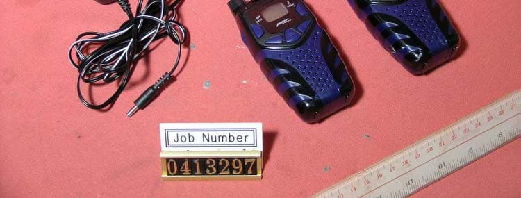
Click to zoom
Application Details
- Equipment Class
- FRF - Part 95 Family Radio Face Held Transmitter
- Date of Grant
- Sep 26, 2004
- Application Purpose
- Original Equipment
- Date of Application
- Sep 26, 2004
- Equipment Note
- Two Way Radio with FRS and GMRS
- Frequency Range
- 467.56250000 - 467.71250000
- Company
- Giant Electronics Ltd
- Country
- Hong Kong
Documents & Files
Document Text
Text extracted from the exhibit documents filed with the FCC. Open a document above to read the original.
Users Manual
User’s Guide Model RT210 FRS/ GMRS Recreational Two-Way Radios FRS/ GMRS Recreational Two-Way Radios KEM-PK10751 Realtree 08-24-04.qxd 8/24/04 10:01 AM Page 1 Realtree 08-24-04.qxd 8/24/04 10:01 AM Page 2 Contents Safety and General Information........................ 2 FCC Licensing Information ..............................10 Control Buttons..................................................11 Getting Started ..................................................12 Installing the AA Batteries..................................12 Installing the NiMH Battery Pack......................12 Battery Meter....................................................13 Attaching the Belt Clip......................................14 Removing the Belt Clip......................................14 Turning Your Radio On and Off........................14 Setting the Volume............................................14 Setting a Channel..............................................15 Channels and Frequencies................................15 Talking and Listening........................................16 Talk Range........................................................16 Checking the Channel Before Transmitting......16 Special Features ................................................17 Interference Eliminator Code............................17 Push to Talk Timeout Timer..............................17 Locking the Keypad..........................................17 Scanning Channels ..........................................18 Advanced Scan ................................................18 Alerts ..................................................................19 Channel Busy Indicator ....................................19 Setting and Transmitting Call Tones ................19 Transmitting a Talk Confirmation Tone..............20 Accessories........................................................21 Using Audio Accessories..................................21 Hands - Free Use (VOX / iVOX) ......................22 Setting the Sensitivity Level..............................22 Warranty..............................................................23 Copyright Information......................................28 1 Contents Contents Realtree 08-24-04.qxd 8/24/04 10:01 AM Page 3 Important Information on Safe and Efficient Operation Read This Information Before Using Your Radio The information provided in this document supersedes the general safety information in user guides published prior to December 1, 2002. Transmit and Receive Procedure Your two-way radio contains a transmitter and a receiver. To control your exposure and ensure compliance with the general population/uncontrolled environment exposure limits, always adhere to the following procedure: uTransmit no more than 50% of the time. uTo transmit (talk), press the Push to Talk (PTT) button. uTo receive calls, release the PTT button. Transmitting 50% of the time, or less, is important because the radio generates measurable RF energy exposure only when transmitting (in terms of measuring standards compliance). Exposure To Radio Frequency Energy Your two-way radio complies with the following RF energy exposure standards and guidelines: uUnited States Federal Communications Commission, Code of Federal Regulations; 47CFR part 2 sub-part J 2 Safety and General Information Safety and General Information Realtree 08-24-04.qxd 8/24/04 10:01 AM Page 4 uAmerican National Standards Institute (ANSI) / Institute of Electrical and Electronic Engineers (IEEE) C95. 1-1992 uInstitute of Electrical and Electronic Engineers (IEEE) C95.1-1999 Edition uInternational Commission on Non-Ionizing Radiation Protection (ICNIRP) 1998 uMinistry of Health (Canada) Safety Code 6. Limits of Human Exposure to Radiofrequency Electromagnetic Fields in the Frequency Range from 3 kHz to 300 GHz, 1999 uAustralian Communications Authority Radiocommunications (Electromagnetic Radiation --- Human Exposure) Standard, 2003 uANATEL ANNEX to Resolution No. 303 of July 2, 2002 "Regulation of limitation of exposure to electrical, magnetic and electromagnetic fields in the radio frequency range between 9 KHz and 300 GHz" and "Attachment to Resolution No. 303 from July 2, 2002" To assure optimal radio performance and make sure human exposure to radio frequency electromagnetic energy is within the guidelines set forth in the above standards, always adhere to the following procedures. Portable Radio Operation and EME Exposure Antenna Care Use only the supplied or an approved replacement antenna.Unauthorized antennas, modifications, or attachments could damage the radio and may violate FCC regulations. DO NOT hold the antenna when the radio is “IN USE”.Holding the antenna affects the effective range. Safety and General Information Safety and General Information 3 Realtree 08-24-04.qxd 8/24/04 10:01 AM Page 5 Two-way Radio Operation When using your radio as a traditional two-way radio,hold the radio in a vertical position with the microphone 1 to 2 inches (2.5 to 5 cm) away from the lips. Body-Worn Operation To maintain compliance with FCC/Health Canada RF exposure guidelines, if you wear a radio on your body when transmitting, always place the radio in a supplied or approved clip, holder, holster, case, or body harness for this product. Use of non-approved accessories may exceed FCC/Health Canada RF exposure guidelines. If you do not use one of the supplied or approved body-worn accessories, and are not using the radio held in the normal use position, ensure the radio and its antenna are at least 1 inch (2.5 cm) from your body when transmitting. Data Operation If applicable, when using any data feature of the radio with or without an accessory cable, position the radio and its antenna at least 1 inch (2.5 cm) from the body. Electromagnetic Interference/Compatibility Note:Nearly every electronic device is susceptible to electromagnetic interference (EMI) if inadequately shielded, designed, or otherwise configured for …
Text truncated - open the document above for the full version.
Users Manual
Potentially Explosive Atmospheres Turn off your radio prior to entering any area with a potentially explosive atmosphere, unless it is a radio type especially qualified for use in such areas as “intrinsically safe”. Do not remove, install, or charge batteries in such areas. Sparks in a potentially explosive atmosphere can cause an explosion or fire resulting in bodily injury or even death. Note:The areas with potentially explosive atmospheres referred to above include fueling areas such as below decks on boats, fuel or chemical transfer or storage facilities, areas where the air contains chemicals or particles, such as grain,dust, or metal powders, and any other area where you would normally be advised to turn off your vehicle engine. Areas with potentially explosive atmospheres are often but not always posted. Blasting Caps and Areas To avoid possible interference with blasting operations, turn off your radio when you are near electrical blasting caps, in a blasting area, or in areas posted: “Turn off two-way radio.” Obey all signs and instructions. Operational Cautions Antennas Do not use any portable radio that has a damaged antenna.If a damaged antenna comes into contact with your skin, a minor burn can result. Safety and General Information Safety and General Information 7 Realtree 08-24-04.qxd 8/24/04 10:01 AM Page 9 Batteries All batteries can cause property damage and/or bodily injury such as burns if a conductive material such as jewelry, keys, or beaded chains touch exposed terminals. The conductive material may complete an electrical circuit (short circuit) and become quite hot. Exercise care in handling any charged battery, particularly when placing it inside a pocket, purse, or other container with metal objects. Battery Charger Safety Instructions Save these Instructions 1. Do not expose the charger to rain or snow. 2.Do not operate or disassemble the charger if it has received a sharp blow, or has been dropped or damaged in any way. 3.Never alter the AC cord or plug provided with the unit. If the plug will not fit the outlet, have the proper outlet installed by a qualified electrician. An improper condition can result in a risk of electric shock. 4.To reduce the risk of damage to the cord or plug, pull the plug rather than the cord when disconnecting the charger from the AC receptacle. 5.To reduce the risk of electric shock, unplug the charger from the outlet before attempting any maintenance or cleaning. 6.Use of an attachment not recommended or sold with unit may result in a risk of fire, electric shock, or personal injury. 8 Safety and General Information Safety and General Information Realtree 08-24-04.qxd 8/24/04 10:01 AM Page 10 7. Make sure the cord is located so it will not be stepped on, tripped over, or subjected to damage or stress. 8.An extension cord should not be used unless absolutely necessary. Use of an improper extension cord could result in a risk of fire and/or electric shock. If an extension cord must be used, make sure that: uThe pins on the plug of the extension cord are the same number, size and shape as those on the plug of the charger. uThe extension cord is properly wired and in good electrical condition. uThe cord size is 18 AWG for lengths up to 100 feet, and 16 AWG for lengths up to 150 feet. 9.The supply cord of this charger cannot be replaced. If the cord is damaged, call Customer Service at 1-800-638-5156 in USA or Canada. Safety and General Information Safety and General Information 9 Realtree 08-24-04.qxd 8/24/04 10:01 AM Page 11 FCC Licensing Information Your radio operates on General Mobile Radio Service (GMRS) frequencies and is subject to the Rules and Regulations of the Federal Communications Commission (FCC). The FCC requires that all operators using GMRS frequencies obtain a radio license before operating their equipment. To obtain the FCC forms, please request Form 605and 159,which includes all forms and instructions. If you wish to have the document faxed or mailed, or have questions, please use the following contact information. Faxed Contact the Fax-On- Demand system at: Mailed Call the FCC forms hotline at: Questions Regarding FCC license Contact the FCC at: 1-202-418-0177 1-800-418-FORM (1-800-418-3676) 1-888-CALL-FCC (1-888-225-5322) Or: http://www.fcc.gov Changes or modifications not expressly approved may void the user’s authority granted by the FCC to operate this radio and should not be made. To comply with FCC requirements, transmitter adjustments should be made only by or under the supervision of a person certified as technically qualified to perform transmitter maintenance and repairs in the private land mobile and fixed services as certified by an organization representative of the user of those services. Replacement of any transmitter component (crystal, semiconductor, etc.) not authorized by the FCC equipment authorization for this radio could violate FCC rules. Note:Use of this radio outside the country where it was intended to be distributed is subject to government regulations and may be prohibited. 10 FCC Licensing Information FCC Licensing Information Realtree 08-24-04.qxd 8/24/04 10:01 AM Page 12 Use “MODE”to: uSelect menu options uExit the menu (when pressed while in a menu) uLock and unlock the keypad (when held down and not in a menu) Accessory Jack Use “MON”to: uMonitor Use and to: uScroll through menus Microphone Useto: uTurn radio on/off uAdjust volume LED Indicator Light Useto: uTalk uSave a setting Use“CALL”to: uTransmit call tone Speaker Control Buttons - Model RT210 l + Control Buttons - Model RT210 Control Buttons - Model RT210 11 Realtree 08-24-04.qxd 8/24/04 10:01 AM Page 13 Getting Started Installing the AA Batteries Your radio uses 3 AA Alkaline batteries. 1.With the back of the radio facing you, lift the battery latch up to release the battery cover and remove the cover. 2.Insert 3 AA Alkaline batteries as shown on the inside of the battery compartment. 3.Reposition the battery cover and press…
Text truncated - open the document above for the full version.
Users Manual
Getting Started Getting Started 15 Setting a Channel Your radio has 22 channels. Channels 1-7 and 15-22 are 1 watt. Channels 8-14 are 0.5 watt. When the radio is on a 1 watt channel, displays. The High power icon will be turned off when the radio is on a 0.5 watt channel. 1.With the radio on, press “MODE”. The current channel flashes. 2.Press or to set the channel. 3.Press to save the channel setting. Channels and Frequencies Channel 1 2 3 4 5 6 7 8 9 10 11 Frequency 462.5625 MHz 462.5875 MHz 462.6125 MHz 462.6375 MHz 462.6625 MHz 462.6875 MHz 462.7125 MHz 467.5625 MHz 467.5875 MHz 467.6125 MHz 467.6375 MHz Description GMRS/FRS GMRS/FRS GMRS/FRS GMRS/FRS GMRS/FRS GMRS/FRS GMRS/FRS FRS FRS FRS FRS Channel 12 13 14 15 16 17 18 19 20 21 22 Frequency 467.6625 MHz 467.6875 MHz 467.7125 MHz 462.5500 MHz 462.5750 MHz 462.6000 MHz 462.6250 MHz 462.6500 MHz 462.6750 MHz 462.7000 MHz 462.7250 MHz Description FRS FRS FRS GMRS GMRS GMRS GMRS GMRS GMRS GMRS GMRS + l Realtree 08-24-04.qxd 8/24/04 10:01 AM Page 17 To communicate, all radios in your group must be set to the same channel and Interference Eliminator Code. To talk, press and hold . Hold the radio 2 to 3 inches away from your mouth when talking. When you finish talking, release (press to talk, release to listen). Talk Range Your radio is designed to maximize performance and improve transmission range. Do not use the radios closer than 5 feet apart. Checking the Channel Before Transmitting Your radio has multiple channels shared on a "take turns" basis. For uninterrupted communication, do not talk on a channel if someone else is currently talking on it. To check for activity on a channel before you talk, press and hold “MON”.If you hear static, the channel is clear to use. 16 Talking and Listening Talking and Listening Realtree 08-24-04.qxd 8/24/04 10:01 AM Page 18 Special Features Interference Eliminator Code Interference Eliminator Codes help minimize interference by providing you with a choice of code combinations. To set the code for a channel: 1.Press “MODE”twice until the code starts to flash. 2.Press or to select the code. 3.Press to save the code setting. You can set a different code for each channel using this procedure. Note:You must set the Interference Eliminator Code to on an FRS radio that uses Interference Eliminator Codes to communicate with other FRS radios that do not have Interference Eliminator Codes. Push to Talk Timeout Timer To prevent accidental transmissions and save battery life, the radio emits a continuous warning tone and stops transmitting if you pressfor60 continuous seconds. Locking the Keypad To avoid accidentally changing your radio settings, press and hold “MODE”for 3 seconds or until displays. You can still turn the radio on and off, adjust the volume, receive, transmit, send a call tone, and monitor channels. All other functions are locked. To unlock the radio, press and hold “MODE”for 3 seconds or until is no longer displayed. + l Special Features Special Features 17 Realtree 08-24-04.qxd 8/24/04 10:01 AM Page 19 Scanning Channels Use scanning to monitor channels and codes for transmissions or to find someone in your group who has accidentally changed channels. To start scanning, briefly press and release “MON”. The scan indicator displays . When the radio detects channel activity, it stops scanning and you can hear the transmission. To respond to the transmission, press within 5 seconds. Note:If your radio's Interference Eliminator Code is set to while scanning, the radio checks for activity on each channel regardless of the code used on the channel. If your radio's Interference Eliminator Code is set to , the radio checks for activity only on channels using codes and Advanced Scan If the radio stops scanning on a channel you do not want to listen to, briefly press and release or to resume scanning for the next active channel. Removing Channels from the Scan List To remove a channel so the radio does not stop on it while scanning, press and hold or for at least 3 seconds, then release. This temporarily removes the channel from the scan list. To restore the channel, turn the radio off and then back on. Note:You cannot remove the channel your radio was set to when you started the scan (called your home channel). 18 Special Features Special Features + l + l ignores channels using code . Realtree 08-24-04.qxd 8/24/04 10:02 AM Page 20 Alerts Channel Busy Indicator When a channel is busy, the LED flashes twice per second. Setting and Transmitting Call Tones Your radio can transmit different call tones to other radios in your group so you can alert them that you want to talk. To set a call tone: 1.With the radio on, press “MODE”3 times. The current call tone setting flashes and displays. 2.Press or to change and hear the call tone. 3.Press “MODE”or to set the new call tone. To transmit your call tone to other radios, set to the same channel and Interference Eliminator Code as your radio and press “CALL”. Notes uThe RT210 model has 10 call tones. uSetting the call tone to disables the call tone feature. + l Alerts Alerts 19 Realtree 08-24-04.qxd 8/24/04 10:02 AM Page 21 Transmitting a Talk Confirmation Tone You can set your radio to transmit an unique tone when you finish transmitting. It's like saying Roger or Over to let others know you are finished talking. uTo turn talk confirmation on, press and hold while you turn the radio on. When you release after transmitting, your call tone transmits and displays. uTo turn talk confirmation off, turn your radio off and then back on while pressing and holding . 20 Alerts Alerts + + Realtree 08-24-04.qxd 8/24/04 10:02 AM Page 22 Accessories There is one audio accessory available for your radio. Using Audio Accessories 1.Turn the radio off. Plug the accessory connector into the jack. See page 11 for the location of the accessory jack on your radio. 2.Turn the radio on. Lower the volume before placing the accessory on your head or in your ear. 3.Press “MON”while rotating…
Text truncated - open the document above for the full version.
External Photos
Test Setup FCC ID : K7GT8270D External Photo - front External Photo - rear
ID Label/Location Info
Sequential four-digit number. The numbers will start over at the start of each week/month. A--2000, B--2001, C--2002, D--2003, E--2004, F--2005, G--2006,.......EG. DG NT/FY APC CODE ( CUSTOMER SUPPLY THIS INFO)
Internal Photos
Test Setup FCC ID : K7GT8270D Internal Photo - 1 Internal Photo - 2 Test Setup FCC ID : K7GT8270D Internal Photo - 3 Internal Photo - 4 Test Setup FCC ID : K7GT8270D Internal Photo - 5 Internal Photo - 6 Test Setup FCC ID : K7GT8270D Internal Photo - 7 Internal Photo - 8 Test Setup FCC ID : K7GT8270D Internal Photo - 9
Parts List/Tune Up Info
ItemDescriptionLocation 1T8270 FRS AMERICA CM WITH CHARGER 2T8270 ASSEMBLY AMERICA CM 3T8270 BASE CASING AMERICA CM 4BASE CASING COMMON 5BATT PLATE"+""-" (C)E503 6BATT PLATE "-""+" (D)E503 7ANTENNA SPRINGE: 8BATT PLATE -E509 9CHARGING CONTACT 10DOME 11LENS PROTECT FILME514 12DOUBLE TAPEE514 13SHIELD COPPERE: 14SPEAKER NET DIA.35 15MIC CUSHION COVERE: 16SPEAKER CUSHIONE: 17SPEAKER SPONGE 18ANTENNA INSERT BLACK 19BELT CLIP COVER BLACK 20TAPTITE SCREW X/HD T2.3X8 21BASE CASING AMERICA CM 22ANTENNA SPRING 23KEYPAD BLACK 24PTT BLACK 25FRONT HOUSING CAMOUFLAGE 26FRONT HOUSING BLACK 27REAR HOUSING BLACK 28BATTERY DOOR BLACK 29LCD LENS WITH PRINTING FOR CN 30LCD LENS W/O PRINTING 31PRINTING FOR LCD LENS CM 32LED LENS 33ANTENNA SHROUD BLACK 34VOLUME KNOB W/O PRINTING 35DUST CAP BLACK 36BASE RF & MAIN PCB (ALL) 37BASE CASING COMMON PARTS 38STRAND WIRE UL1007 #28 BLACKJW201L=45MM 39STRAND WIRE UL1007 #28 REDJW202L=45MM 40MIC EM-926A-622 WELLINMIC101 41SPEAKER 32 OHM 0.5W 3632A505SPK101 42BASE RF & MAIN COMMON PARTS 43CAP. ELECT 6.3V M 10UF 4X5MMC172 44CAP.ELECT 6.3V M 100UF 5X5MMC242 45CAP. ELECT 6.3V M 220UF 6X5MMC248 46CAP. ELECT 6.3V M 470UF 6X8MMC237 47SAW FILTER 465MHZ SF465 AEIBPF101 48CRYSTAL FILTER 21.4MHZ AEI 21.4N7.5A2BPF102 49CERAMIC FILTER CFT450HT HUATAMOBPF105 504DIGIT WITH ICON 22X20X1.7MM TB4320ALCD101 51DIA 2.5mm EARPHONE JACK ST-101J101 52 HEAT SEAL CABLE P=0.6MM L=10MM 12PINS K&KJW203 53COIL FIXED 2U2H 5%L112 54BATT PLATE + 55SHIELD WHOLE 56LCD BRACKET 57COPPER PAPER 58WHITE SHEET 59LCD CUSHION 60LCD LIGHT GUIDE 61JTB 450KHZ CERAMIC DISCRIMINATORL114 62RES.SEMI.F-09115SA A5KB L14.6FCX7VR103 63SLIDE TACT SWITCH TS-37-BH-DGK102 64CERAMIC RESONATOR 4MHZ +/-0.2%X102 65BASE RF & MAIN PCB SMT COMMON PARTS 66BASE RF & MAIN PCB SMT BOTTOM COMMON PARTS 67CAP.CER.CHIP 50V D% 10PF NPO MURATAC180 FOR MATCH B1 CRYSTAL 68CAP.CER.CHIP 50V CH J% 100PF MURATAC142,C255,C284,C309 69CAP. CER. CHIP 16V X7R K 0.01UFC5 70CAP.CER.CHIP 16V F Z% 0.1UF MURATAC264,C124,C170,C173,C175,C108,C222,R 71CAP CER CHIP 6.3V Y5V 1uF Z 0402 MURATAC149,C136,C275 72CAP. CER. CHIP 16V F Z% 1UFC147,C186 73CAP.CER.CHIP 50V CH C% 1PF MURATAC179 FOR MATCH B3/B4 CRYSTAL 74CAP.CER.CHIP 50V CH J% 15PF MURATAC180 FOR MATCH B3 CRYSTAL 75CAP CER CHIP 50V X7R K 0.0015UF MURATAC161,C163 76CAP. CER. CHIP 16V B K 0.015UF MURATAC258 77CAP.CER.CHIP 50V CH J% 18PF MURATAC171 FOR MATCH B4 CRYSTAL 78CAP. CER. CHIP 50V CH J% 20PF MURATAC180 FOR MATCH B4 CRYSTAL 79CAP.CER.CHIP 50V CH J% 22PF MURATAC171 FOR MATCH B1/B3 CRYSTAL 80CAP.CER.CHIP 50V CH J% 24PF MURATAC169 81CAP. CER. CHIP 16V Y7R K0.027UF TDKR290 82CAP. CER. CHIP 50V CH J% 33PFC308,C312,C319,C133 83CAP. CER. CHIP 16V F Z% 0.33UFC253 84CAP. CER. CHIP 50V CH C% 5PF MURATAC165 FOR MATCH B3/B4 CRYSTAL 85CAP. CER. CHIP 50V X7R K 560PFC111 86CAP CER CHIP 50V X7R K 680PF MURATAC260 87CAP. CER. CHIP 25V B K 0.0068UFC198 88CAP. CER. CHIP 50V X7R K 0.068UFC208 89CAP. CER. CHIP 50V CH D 9PF MURATA 0402C165 FOR MATCH B1 CRYSTAL 90DIODE ARRAY CHIP DA204UD103 91LED CHIP KPA-3010EC REDD107,D108 92DIODE PIN 1SS314D106,D2 93THER. NTCCM10053EH220JC TDK 0402 TYPETR102 94RES. CHIP 1/16W 0 OHMR252,R253,C306,R303,R286,R289,C280 95RES. CHIP 1/16W 10 OHMR139 96RES. CHIP 1/16W 1KR270 97RES. CHIP 1/16W 10KR131,R272,R273,R10,R271 98RES. CHIP 1/16W 100KR145,R275,R23 99RES. CHIP 1/16W 1MR115,R241 100RES. CHIP 1/16W 1.2KR110 101RES CHIP 1/16W 5% 12K 0402R184 102RES CHIP 1/16W 5% 120K 0402R136 103RES. CHIP 1/16W 1.5KR293,R101 104RES CHIP 1/16W 5% 160 OHM 0402R104 105RES. CHIP 1/16W 180 0402R189 106RES. CHIP 1/16W 180KR137,R257 107RES CHIP 1/16W 5% 180K 0402R258 108RES. CHIP 1/16W 2.2KR123,R133 109RES. CHIP 1/16W 22KR126 110RES. CHIP 1/16W 22KR12,R284 111RES. CHIP 1/16W 220KR105 112RES CHIP 1/16W 5% 24K 0402R235 113RES. CHIP 1/16W 2.7KR147,R207 114RES CHIP 1/16W 5% 27K 0402R15,R183 115RES. CHIP 1/16W 270K 0402R146 116RES. CHIP 1/16W 330 OHM 0402TR105 117RES. CHIP 1/16W 3.3K 0402R106 118RES. CHIP 1/16W 39 OHM 0402R231 119RES. CHIP 1/16W 39K 0402R260 120RES CHIP 1/16W 5% 390K 0402R132 121RES. CHIP 1/16W 4.7KR11 122RES. CHIP 1/16W 4.7K 0402R9,R274,R225,R226 123RES. CHIP 1/16W 47KR120,R202,R302 124RES. CHIP 1/16W 470K 0402R208,R209,R210,R211,R227,R240 125RES. CHIP 1/16W 5.6K 0402R140 126RES. CHIP 1/16W 56KR201 127RES. CHIP 1/16W 680 OHM 0402R127 128RES. CHIP 1/16W 6.8K 0402R292 129RES CHIP 1/16W 5% 680K 0402R141 130RES. CHIP 1/16W 820R291 131TR CHIP PNP 2SA1586GR4862830A05Q108,Q111 132TR. CHIP PNP 2SA1611-T1 M6 133TR CHIP NPN 2SC4116GRQ2,Q103,Q109,Q121,Q126,Q127,Q128,Q12 134TR. CHIP NPN 2SC4177-T1 L6 135BASE RF & MAIN PCB SMT TOP COMMON PARTS 136CAP. CHIP TR1MMER 10PF TZBX4100AA110C159 137CAP.CER.CHIP 50V CH J% 100PF MURATAC158,C282,C283,C310,C311,C324,C174,C 138CAP. CER. CHIP 50V CH J% 100PFC323 139CAP.CER.CHIP 50V B K% 0.001UF MURATAC164 140CAP CER CHIP 50V X7R +/-10% 0.001u EYANGC164 141CAP. CER. CHIP 50V B K% 0.001UFC206 142CAP. CER. CHIP 50V B K% 1NFC103,C113,C250,C214,C270 143CAP. CER. CHIP 16V X7R K 0.01UFC135,C143,C192,C194,C246,C257 144CAP. CER. CHIP 16V B K% 0.1uFC244 145CAP.CER.CHIP 16V F Z% 0.1UF MURATAC167,C204,C221,C234,C116,C125,C126,C 146CAP CER CHIP 6.3V Y5V 1uF Z 0402 MURATAC157 147CAP CHIP 16V 10% X7R 1uF 0402 MURATAC166 148CAP. CER. CHIP 16V F Z% 1UFC177,C269 149CAP CER CHIP 10V F Z 10UFC232 150CAP. CER. CHIP 10V F Z% 10UFC145,C235,C109 151CAP.CER.CHIP 50V CH C% 1PF MURATAC115 152CAP.CER.CHIP 50V CH J% 12PF MURATAC151 153CAP.CER.CHIP 16V B K% 0.012UF MURATAC184 154CAP.CER.CHIP 50V CH J% 15PF MURATAC132 155CAP. CER. CHIP 50V CH J% 150PF MURATAC322 156CAP. CER. CHIP 50V CH J% 150PFC285 157CAP.CER.CHIP 50V CH C% 1.5PF MURATAC123,C130 158CAP.CER.CHIP 50V CH J% 18PF MURATAC137,C112,C127 159CAP. CER. CHIP 16V B K 0.018UFC241 160CAP CER CHIP 50V COG B 1.8PFC303 161CAP.CER.CHIP 50V CH C% 2PF MURATAC138 162CAP. CER. CHIP 10V X7R K 0.0022UFC209 163CAP.CER.CHIP 16V B K% 22NF MURATAC228,C239,C196,C273,C274,C156 164CAP.CER.CHIP 50V CH J% 24PF MURATAC155 165CAP. CER. CHIP 50V NPO J 27P 0402C190 166CAP.CER.CHIP…
Text truncated - open the document above for the full version.
Parts List/Tune Up Info
Tune Procedure 1) TX VCO ADJUSTMENT a. connect the DC voltmeter at TP103 b. press and hold PTT button c. adjust L113 to 1.0VDC +/-0.2V at CH1 2) FREQUENCY ADJUSTMENT a. connect the frequency counter meter to TP 101 b. adjust C159 to TX frequency +/-200Hz 3) TX POWER CHECK a. connect the RF level meter to the TP101 b. press and hold PTT button c. check the TX power < 0.52 W at CH1 and < 0.17 W at CH14 4) DEVIATION LIMITING AND MIC SENSITIVITY a. connect the deviation meter to TP101 b. apply audio signal 1KHz 25mVrms to TP113 c. press and hold PTT button d. adjust VR101 to 2.2KHz DEV +/-0.2KHz e. check mic sensitivity between 1mVrms and 10mVrms at 1.5KHz DEV • TO PRESS AND HOLD THE PTT BUTTON FOR TX MODE TESTING • TO PRESS AND HOLD MENU AND +, THEN POWER UP FOR RADIO TEST MODE • THE RADIO CAN TRANSMITTING WITHOUT TIMEOUT UNDER TEST MODE
RF Exposure Info
© 2004 Celltech Labs Inc. 1 of 20 Test Report S/N: 081304-550K7G Test Date(s): August 17, 2004 Test Type: FCC/IC SAR Evaluation Celltech Labs Inc. declares under its sole responsibility that this wireless portable device has demonstrated compliance with the Specific Absorption Rate (SAR) RF exposure requirements specified in FCC 47 CFR §2.1093 and Health Canada’s Safety Code 6. The device was tested in accordance with the measurement standards and procedures specified in FCC OET Bulletin 65, Supplement C (Edition 01-01) and Industry Canada RSS-102 Issue 1 (Provisional) for the General Population / Uncontrolled Exposure environment. All measurements were performed in accordance with the SAR system manufacturer recommendations. I attest to the accuracy of data. All measurements were performed by me or were made under my supervision and are correct to the best of my knowledge and belief. I assume full responsibility for the completeness of these measurements and vouch for the qualifications of all persons taking them. This test report shall not be reproduced partially, or in full, without the prior written approval of Celltech Labs Inc. The results and statements contained in this report pertain only to the device(s) evaluated. Russell W. Pipe Senior Compliance Technologist Celltech Labs Inc. DECLARATION OF COMPLIANCE SAR RF EXPOSURE EVALUATION Test Lab CELLTECH LABS INC. Testing and Engineering Services 1955 Moss Court Kelowna, B.C. Canada V1Y 9L3 Phone: 250-448-7047 Fax: 250-448-7046 e-mail: [email protected] web site: www.celltechlabs.com Applicant Information GIANT ELECTRONICS LTD. 7/F, Elite Industrial Bldg. 135-137 Hoi Bun Road Kwun Tong, Kowloon Hong Kong FCC IDENTIFIER: K7GT8270D IC IDENTIFIER: 2415B-T8270D Model(s): T8260D / T8270D / RT210 Rule Part(s): FCC 47 CFR §2.1093; IC RSS-102 Issue 1 (Provisional) Test Procedure(s): FCC OET Bulletin 65, Supplement C (Edition 01-01) Device Type: Portable UHF FRS/GMRS PTT Radio Transceiver Tx Frequency Range(s): 462.5500 - 462.7250 MHz (GMRS Channels 15-22) 462.5625 - 462.7125 MHz (FRS/GMRS Channels 1-7) 467.5625 - 467.7125 MHz (FRS Channels 8-14) Max. RF Output Power Tested: 0.527 Watts (27.22 dBm) ERP (GMRS 462.7125 MHz) Modulation: FM (UHF) Antenna Type(s) Tested: Fixed Helical Battery Type(s) Tested: NiMH (3.6 V, 600 mAh), Alkaline x3 (1.5 V AA) Alkaline Type 1: Duracell Procell (2850 mAh) Alkaline Type 2: Energizer E91 (2850 mAh) Body-Worn Accessories Tested: Plastic Swivel Belt-Clip (P/N: KEM-PK10873) Earbud with Boom-Microphone (P/N: KESP-202) Max. SAR Levels Evaluated: 1.16 W/kg - Face-held (100% duty cycle) 1.10 W/kg - Body-worn (100% duty cycle) © 2004 Celltech Labs Inc. 2 of 20 Test Report S/N: 081304-550K7G Test Date(s): August 17, 2004 Test Type: FCC/IC SAR Evaluation TABLE OF CONTENTS 1.0INTRODUCTION......................................................................3 2.0DESCRIPTION OF DUT............................................................. 3 3.0SAR MEASUREMENT SYSTEM................................................. 4 4.0MEASUREMENT SUMMARY...................................................... 5 5.0DETAILS OF SAR EVALUATION................................................ 6 6.0EVALUATION PROCEDURES.................................................... 6 7.0SYSTEM PERFORMANCE CHECK............................................. 7 8.0SIMULATED EQUIVALENT TISSUES.......................................... 8 9.0SAR SAFETY LIMITS............................................................... 8 10.0ROBOT SYSTEM SPECIFICATIONS............................................ 9 11.0PROBE SPECIFICATION (ET3DV6)............................................ 10 12.0PLANAR PHANTOM................................................................. 10 13.0VALIDATION PHANTOM............................................................ 10 14.0DEVICE HOLDER..................................................................... 10 15.0TEST EQUIPMENT LIST............................................................ 11 16.0MEASUREMENT UNCERTAINTIES............................................. 12-13 17.0REFERENCES.........................................................................14 APPENDIX A - SAR MEASUREMENT DATA............................................... 15 APPENDIX B - SYSTEM PERFORMANCE CHECK DATA............................ 16 APPENDIX C - SYSTEM VALIDATION PROCEDURES................................. 17 APPENDIX D - PROBE CALIBRATION...................................................... 18 APPENDIX E - MEASURED FLUI…
Text truncated - open the document above for the full version.
Contact Information
Applicant
Yumin Zou(A. Manager)
Technical Contact
Intertek Testing Services Hong Kong Ltd.Tommy Leung
[email protected]85221738538
2/F., Garment Center · Kowloon · Hong Kong
Non-Technical Contact
Intertek Testing Services Hong Kong Ltd.Tommy Leung
[email protected]85221738538
Test Firm
Intertek Testing Services Hong KongBilly Chow
Technical Specifications
| # | Rule Parts | Frequency Range | Power Output | Emission | Tolerance |
|---|---|---|---|---|---|
| 2 | 95B | 467.5625 MHz - 467.7125 MHz | 170.00 mW | 10K4F3E | 2.31 ppm |
Other Applications from Giant Electronics Ltd

K7GMDBJJPR
Jun 24, 2012Two Way Radio - FRS
Equipment Class
FRF - Part 95 Family Radio Face Held Transmitter
K7GMTCEJ
Apr 26, 2012Two Way Radio with GMRS and FRS
Equipment Class
CXX - Communications Rcvr for use w/ licensed Tx and CBs
K7GMDBJJ
Mar 01, 2012Two Way Radio with GMRS and FRS
Equipment Class
FRF - Part 95 Family Radio Face Held Transmitter
K7GMSFGJ
Mar 10, 2011Two Way Radio with Weather Band
Equipment Class
CXX - Communications Rcvr for use w/ licensed Tx and CBs
K7GT2007
Apr 08, 2010Two Way Radio with GMRS and FRS
Equipment Class
FRF - Part 95 Family Radio Face Held Transmitter