KA349WAN2HIGH CAPACITY WIRELESS BRIDGING/ROUTING SYSTEM
Solectek Corporation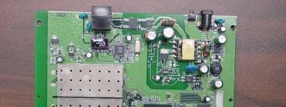
Click to zoom
Application Details
- Equipment Class
- TNB - Licensed Non-Broadcast Station Transmitter
- Date of Grant
- Sep 13, 2005
- Application Purpose
- Original Equipment
- Date of Application
- Sep 13, 2005
- Equipment Note
- HIGH CAPACITY WIRELESS BRIDGING/ROUTING SYSTEM
- Frequency Range
- 4940.00000000 - 4990.00000000
- Company
- Solectek Corporation
- Country
- United States
Documents & Files
Document Text
Text extracted from the exhibit documents filed with the FCC. Open a document above to read the original.
Users Manual
1 SKYWAY 4000 Series User’s Guide 1. Introduction Congratulations on your purchase of Solectek’s SKYWAY 4000 Series Bridge/Router, a feature rich, best-in-class wireless solution. This User’s Guide will describe the operation of your SKYWAY 4000 unit in detail. SYSTEM FEATURES • Field proven OFDM modulation allowing near line-of-sight deployment and strong immunity to multi-path. • Data rates from 6 Mbps to 72 Mbps. • High power radio and improved radio sensitivity for best in class link ranges – over 10 miles with only 1-foot panel antenna. • Power over Ethernet (PoE) for simplified cable routing – only a single outdoor CAT5 cable is needed. • Integrated antenna/radio simplifies installation and eliminates lossy RF coax runs. • AES encryption for the ultimate in security and data protection. • Client access control via MAC address filtering. • Intuitive Web based user interface. PACKAGE CONTENTS • (2) SKYWAY point-to-point radios: 4101, 4301 or 4501. • (2) 24VDC Power Supplies. • (2) Power over Ethernet (PoE) injectors. • (2) Two-axis mast mounting kits. • (2) Ethernet cable weatherproofing glands. • CD-ROM containing documentation and software utilities. • Registration Card. • Warranty and Compliance Card. NOTE: CAT5 Ethernet cable is not included in the package. Please contact Solectek for information on available UV-protected Ethernet cables for outdoor use. System Requirements • Indoor CAT 5 cable – straight cable if connecting to a hub/switch, cross-over cable if connecting to a PC. • A computer running TCP/IP over Ethernet for testing of the client in a live multipoint wireless network. 2 2. Physical Installation A. INTRODUCTION Your SkyWay radio is designed to be mast mounted on a rooftop or radio tower. After determining the best location for your radio, installation can begin. (Please refer to Solectek’s RF Site Design Guide on the included documentation CD for more information about choosing an ideal radio location.) B. MOUNTING KIT ASSEMBLY A two-axis mounting kit is included with each SkyWay radio allowing secure, adjustable mounting to a pole or mast. The mounting kit must first be assembled and then attached to the back of the SkyWay radio. Please refer to the printed directions included in the mounting kit box for more information. There are three possible methods in arranging the clamp pieces to accommodate small, medium and large mast diameters. Please refer to the figure on the next page. Note that the middle and rightmost images differ only in the length of bolt used to fasten the two clamp pieces together. The mounting kit attaches to the back of the SkyWay radio by way of four self-tapping screws. Be sure screws are perpendicular to the radio back before driving the screws inward. Wrench tighten all screws/nuts prior to outdoor installation. C. ETHERNET CABLE Only a single, outdoor rated, Cat5 Ethernet cable is needed to connect the Skyway radio to the indoor PoE Injector. To ensure all-weather operation, the included weatherproofing cable gland must be built onto the Ethernet cable. This seal can be slipped onto the Cat5 cable before attaching the RJ45 connectors at the end(s). Note: the total combined length of the two Ethernet cables between the radio and hub/switch/PC must not exceed 300 feet. Note: In order to maintain FCC compliance, use of a shielded Ethernet cable with Skyway 4000 is required. D. INSTALLATION After locating and installing the radio mast, the physical installation of your Skyway 4000 radio can begin. If benchtesting the system first, you may want to skip this step and return to it after testing is completed. 1. Using the clamp on the mast mounting kit, attach the SkyWay radio to the chosen mast. Wrench tighten mast clamp bolts. 2. Using the two axis adjustment pivots, point the radio antenna in the general direction of the target radio. Partially tighten axis bolts so that fine-tuning can be performed later. 3. Connect RJ45 connector to the SkyWay radio. 4. Slide cable gland up the Ethernet cable to radio housing and screw gland into threaded opening. Wrench tighten, but do not overtighten the nylon gland. 5. At opposite end of gland (pointing away from the radio), tighten seal nut against Ethernet cable. Wrench tighten, again being careful not to overtorque the gland. 6. Place PoE Injector and Power Supply in a convenient, indoor location near to the destination hub, switch or PC. 7. Route and connect outdoor Cat5 cable to PoE Injector. 8. You may now plug in the Power Supply to power the unit. 3 3. System Configuration A. CONNECTING THE SKYWAY UNIT FOR CONFIGURATION Using the appropriate diagram below as a guide, cable together your SkyWay test system. Connect your PC to the POE injector using (a) crossover Ethernet cable or (b) straight cable and a hub/switch. B. SET UP YOUR COMPUTER’S TCP/IP PROPERTIES Open networking properties in your Windows OS. Find the TCP/IP setup window of your wired Ethernet adapter. The details on how to set the IP address of your computer’s Ethernet adapter are different, depending on Windows versions (95/98/2000/Me/XP). Please consult your Windows OS documentation. Shown below is the Windows 2000 TCP/IP Properties window. Set the IP addresses to the following values. Ethernet’s IP Address: 192.168.0.100 Subnet Mask: 255.255.255.0 4 C. LOG-IN TO YOUR SKYWAY • Start a Web Browser on your computer (such as Netscape Navigator or Microsoft Explorer). • At the URL line, type in the following: http://192.168.0.1 or http://192.168.0.2 to access the Welcome screen below. The Skyway 4000 Point-to-Point kits are shipped in preconfigured pairs. One unit will be configured to have a default IP address of 192.168.0.1 and the other will have an IP address of 192.168.0.2. • Click on the login menu option located in the navy-blue left menu bar. The following screen should appear: • The default username is admin and the default password is default. Once logged in, the password can be changed. Click OK and you will see the Main…
Text truncated - open the document above for the full version.
Cover Letter(s)
September 9, 2005 TIMCO ENGINEERING, INC. 849 N.W. State Road 45 P.O. Box 370 Newberry, Florida 32669 Re: Request of Confidentiality FCC ID: KA349WAN2 Pursuant to Sections 0.457(d)(1)(ii) and 0.459 of the Commission’s Rules, the Applicant hereby requests confidential treatment of information accompanying as outlined below: Schematics Parts List The above materials contain trade secrets and proprietary information not customarily released to the public. The public disclosure of these matters might be harmful to the Applicant and provide unjustified benefits to its competitors. The Applicant understands that pursuant to Rule 0.457(d)(1)(ii), disclosure of this Application and all accompanying documentation will not be made before the date of the Grant for this Application. Sincerely, David Gell VP Engineering 858-450-1220 858-457-2681 (fax)
External Photos
External Photos Top Left Side Top Right Side Bottom Right Side Bottom Left Side
ID Label/Location Info
ID Label/Location Information Label Location Label Sample
Internal Photos
Internal Photos Photo 1: Assembly Photo 2: PCB1 top with shield Photo 3: PCB1 top without shield Photo 4: PCB1 bottom Photo 5: PCB2 top Photo 6: PCB2 bottom
Operational Description
Skyway 4000 Operational Description Skyway 4000 Series is a high capacity wireless bridging and/or routing system. It makes use of OFDM digital modulation in the 4940 MHz to 4990MHz frequency band. The transceiver is integrated into the antenna. The unit is tuned to the right frequency and power level by software as soon as it is powered up. The system is intended for outdoor use such that the integrated transceiver and antenna is mounted outdoors and a single Ethernet cable connects it to the power supply and indoor user’s network. That is, it incorporates POE (power over Ethernet). The DC Power is injected into the Ethernet cable via an indoor Power Injector Unit (PIU). The PIU has two inputs, power supply and Ethernet, and one output, the POE. Unit will be professionally installed. The Skyway 4000 Series comes in a variety of flavors. These include both Point-to-Point bridges and Point-to- Multipoint Routers with various EIRP dependent on which antenna is used.
Parts List/Tune Up Info
September 13, 2005 TIMCO ENGINEERING, INC. 849 N.W. State Road 45 P.O. Box 370 Newberry, Florida 32669 Attn: Reviewing Engineer RE: Tune Up Procedure FCC ID: KA349WAN2 To Whom it May Concern: The Solectek Skyway 4000 with the above referenced FCC ID, has no field hardware adjustment points. All configuration changes possible are made via software, and are as described in the User Manual for this equipment. Therefore, there is no separate tune up procedure to submit. Sincerely, David Gell VP Engineering 858-450-1220 858-457-2681 (fax)
Test Report
TEST REPORT FROM d For Skyway 4000 Radio -2 To FCC Part 90 Subpart Y Test Report Serial No.: SL05081801-SLK-001B This report supersedes NONE Remarks: Equipment complied with the specification [X ] Equipment did not comply with the specification [ ] This Test Report is Issued Under the Authority of: .......................................................................................................... Tested by: Alvin Ilarina, Test Enginner .......................................................................................................... Reviewed by: Leslie Bai, Lab Manager Issue date: 06 September 2005 Equipment Details: Manufacturer: Solectek Corporation This test report may be reproduced in full only. Registration No. 783147 Registration No. 2195 Registration No. 4842 RTA No. D23/16V Lab Code: KR0032 Title: Solectek Corporation Skyway 4000 Radio -2 To: FCC Part 90 Subpart Y Serial# SL05081801-SLK-001B Issue Date 06 September 2005 Page 2 of 34 This page has been left blank intentionally. Title: Solectek Corporation Skyway 4000 Radio -2 To: FCC Part 90 Subpart Y Serial# SL05081801-SLK-001B Issue Date 06 September 2005 Page 3 of 34 CONTENTS EXECUTIVE SUMMARY..............................................................................................................................................5 1 TECHNICAL DETAILS..........................................................................................................................................6 2 TESTS REQUIRED..................................................................................................................................................7 3 MEASUREMENTS, EXAMINATIONS AND DERIVED RESULTS.................................................................8 4 TEST INSTRUMENTATION................................................................................................................................27 APPENDIX A: EUT TEST CONDITIONS.................................................................................................................28 APPENDIX B: EXTERNAL PHOTOS........................................................................................................................29 APPENDIX C: CIRCUIT/BLOCK DIAGRAMS.......................................................................................................30 APPENDIX D: INTERNAL PHOTOS.........................................................................................................................31 APPENDIX F: PRODUCT DESCRIPTION...............................................................................................................32 APPENDIX H: FCC LABEL LOCATION..................................................................................................................33 APPENDIX I: USER MANUAL...................................................................................................................................34 Title: Solectek Corporation Skyway 4000 Radio -2 To: FCC Part 90 Subpart Y Serial# SL05081801-SLK-001B Issue Date 06 September 2005 Page 4 of 34 This page has been left blank intentionally. Title: Solectek Corporation Skyway 4000 Radio -2 To: FCC Part 90 Subpart Y Serial# SL05081801-SLK-001B Issue Date 06 September 2005 Page 5 of 34 Executive Summary The purpose of this test programme was to demonstrate compliance of the Solectek Corporation, Skyway 4000 Radio -2 against the current FCC Part 90 Subpart Y. The Skyway 4000 Radio -2 demonstrated compliance with the FCC Part 90 Subpart Y. Solectek Corporation is the applicant and claimed manufacturer of this tested product. For the detailed description of this product, please refer to the Skyway 4000 Radio -2 User Manual. The test has demonstrated that this unit complies with stipulated standards. Title: Solectek Corporation Skyway 4000 Radio -2 To: FCC Part 90 Subpart Y Serial# SL05081801-SLK-001B Issue Date 06 September 2005 Page 6 of 34 1 Technical Details Purpose Compliance testing of Skyway 4000 Radio -2 with FCC Part 90 Subpart Y Applicant / Client Solectek Corporation 6370 Nancy Ridge Dr. Suite 109 San Diego, CA 92121-3212 Manufacturer Solectek Corporation Laboratory performing the tests SIEMIC Labs 2206 Ringwood Avenue San Jose, CA 95131 Test location(s) SIEMIC Labs 2206 Ringwood Avenue San Jose, CA 95131 Test report reference number SL05081801-SLK-001B Date EUT received 30 Aug 2005 Standard applied FCC Part 90 Subpart Y Dates of test (from – to) 30 Aug 2005 to 30 Sep 2005 No of Units: 1 Equipment Category: Licensed Non-Broadcast Station Transmitter Trade/Product Name: Skyway 4000 Radio -2 Type/Model Name/No: Skyway 4000 Radio -2 Technical Variants: None FCC ID No. KA349WAN2 Title: Solectek Corporation Skyway 4000 Radio -2 To: FCC Part 90 Subpart Y Serial# SL05081801-SLK-001B Issue Date 06 September 2005 Page 7 of 34 2 Tests Required The product was tested in accordance with the following specifications. The test results recorded in this Test Report are exclusively referred to the tested sample(s). Test Standard Description Pass / Fail 47 CFR Part 90, Subpart Y 2.1046; 90.1215(a) Peak Output Power Pass 2.1046; 90.1215(a) Peak Power Spectral Density Pass 2.1049; 90.210(m) Occupied Bandwidth; Emissions Mask Pass 2.1051; 90.210(m) Spurious Emissions at Antenna Terminals Pass 2.1053; 90.210(m) Radiated Spurious Emissions Pass 2.1055(a)(1); 90.213 Frequency Stability; Temperature Variations Pass 2.1055(d)(1); 90.213 Frequency Stability; Voltage Variations Pass TIA/EIA-603-A-2001 ANSI C63.4: 2001 Notes: Deviations to above standards are outlined in specific test sections if applicable. Cable loss and external attenuation are compensated for in the measurement system when applicable. Title: Solectek Corporation Skyway 4000 Radio -2 To: FCC Part 90 Subpart Y Serial# SL05081801-SLK-001B Issue Date 06 September 2005 Page 8 of 34 3 Measurements, Examinations and Derived Results 3.1 General observations Equipment serial number(s) Module: Part nu…
Text truncated - open the document above for the full version.
Test Setup Photos
Test Setup Photos Radiated Emissions Conducted Emissions Temperature Stability
Contact Information
Applicant
Eric Lee(President)
Technical Specifications
| # | Rule Parts | Frequency Range | Power Output | Emission | Tolerance |
|---|---|---|---|---|---|
| 3 | 9 | 4.94 GHz - 4.99 GHz | 70.00 mW | 10M0X1D | 8 ppm |
Other Applications from Solectek Corporation
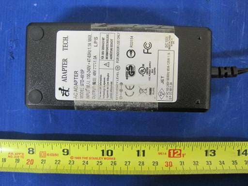
KA349WAN3
Aug 13, 2014Outdoor Broadband Wireless Radio
Equipment Class
TNB - Licensed Non-Broadcast Station Transmitter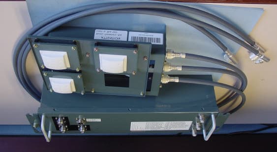
KA358MRS1
Jan 31, 2008Wireless Telemetry Transceiver
Equipment Class
DTS - Digital Transmission System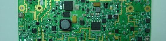
KA349WAN1
Sep 13, 2005HIGH CAPACITY WIRELESS BRIDGING/ROUTING SYSTEM
Equipment Class
TNB - Licensed Non-Broadcast Station Transmitter
KA358WAN2
Jun 13, 2005Ethernet Bridge / Transceiver
Equipment Class
DTS - Digital Transmission System
KA358WAN1
Oct 22, 2003DIGITAL TRANSCEIVER SYSTEM
Equipment Class
DXX - Part 15 Low Power Communication Device Transmitter