KA358WAN2Ethernet Bridge / Transceiver
Solectek Corporation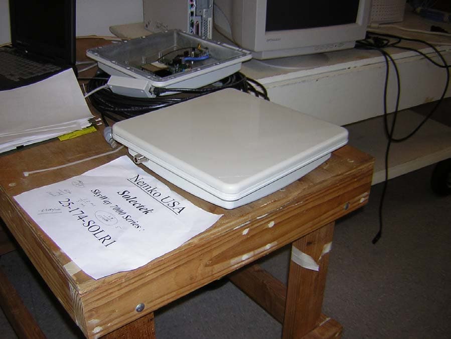
Click to zoom
Application Details
- Equipment Class
- DTS - Digital Transmission System
- Date of Grant
- Jun 13, 2005
- Application Purpose
- Original Equipment
- Date of Application
- Jun 13, 2005
- Equipment Note
- Ethernet Bridge / Transceiver
- Frequency Range
- 5745.00000000 - 5825.00000000
- Company
- Solectek Corporation
- Country
- United States
Documents & Files
Document Text
Text extracted from the exhibit documents filed with the FCC. Open a document above to read the original.
Users Manual
1 SKYWAY 7000 Series User’s Guide 1. Introduction Congratulations on your purchase of Solectek’s SKYWAY 7000 Series Bridge/Router, a feature rich, best-in-class wireless solution. This User’s Guide will describe the operation of your SKYWAY 7000 unit in detail. S YSTEM F EATURES • Field proven OFDM modulation allowing near line-of-sight deployment and strong immunity to multi-path. • Data rates from 6 Mbps to 72 Mbps. • High power radio (400mW) and improv ed radio sensitivity for best in class link ranges – over 10 miles with only 1-foot panel antenna. • Power over Ethernet (PoE) for simpli fied cable routing – only a single outdoor CAT5 cable is needed. • Integrated antenna/radio simplifies installation and eliminates lossy RF coax runs. • AES encryption for the ultimate in security and data protection. • Client access control vi a MAC address filtering. • Intuitive Web based user interface. P ACKAGE C ONTENTS • (2) SKYWAY point-to-point radios: 7101, 7301 or 7501. • (2) 24VDC Power Supplies. • (2) Power over Ethernet (PoE) injectors. • (2) Two-axis mast mounting kits. • (2) Ethernet cable weatherproofing glands. • CD-ROM containing documentation and software utilities. • Registration Card. • Warranty and Compliance Card. NOTE: CAT5 Ethernet cable is not included in the package. Please contact Solectek for information on available UV -protected Ethernet cables for outdoor use. System Requirements • Indoor CAT 5 cable – straight cabl e if connecting to a hub/switch, cross-over cable if connecting to a PC. • A computer running TCP/IP over Ethern et for testing of the client in a live multipoint wireless network. 2 2. Physical Installation A. I NTRODUCTION Your SkyWay radio is designed to be mast mounted on a rooftop or radio tower. After determining the best loca tion for your radio, installation can begin. (Please re fer to Solectek’s RF Site Design Guide on the included documentation CD for more informat ion about choosing an ideal radio location.) B. M OUNTING K IT A SSEMBLY A two-axis mounting kit is included with each SkyWay radio allowing secure, adjustable mounting to a pole or mast . The mounting kit must first be assembled and then attached to the back of the SkyWay radio. Please refer to the printed directions included in the mounting kit box for more information. There are three possible methods in arranging the clamp pieces to accommodate small, medium and large ma st diameters. Please refer to the figure on the next page. Note that the middle and rightmost images differ only in the length of bolt used to fasten the two clamp pieces together. The mounting kit attaches to the back of the SkyWay radio by way of four self-tapping screws. Be sure screws are perpendicular to the radio back before driving the screws inward. Wrench tighten all screws/nuts prior to outdoor installation. C. E THERNET C ABLE Only a single, outdoor rated, Cat5 Ethe rnet cable is needed to connect the Skyway radio to the indoor PoE Injector . To ensure all-weather operation, the included weatherproofing cable glan d must be built on to the Ethernet cable. This seal can be slipped onto the Cat5 cable before attaching the RJ45 connectors at the end(s). Note: the total combined length of the two Ethernet cables between the radio and hub/switch/PC must not exceed 300 feet. Note: In order to maintain FCC compliance, use of a shielded Ethernet cable with Skyway 7000 is required. D. I NSTALLATION After locating and installing the radio mast, the physical installation of your Skyway 7000 radio can begin. If benchtesting the sy stem first, you may want to skip this step and return to it after testing is completed. 1. Using the clamp on the mast mounting kit, attach the SkyWay radio to the chosen mast. Wrench tighten mast clamp bolts. 2. Using the two axis adjustment pivots, point the radio antenna in the general direction of the ta rget radio. Partially tighten axis bolts so that fine-tun ing can be performed later. 3. Connect RJ45 connector to the SkyWay radio. 4. Slide cable gland up the Ethernet cable to radio housing and screw gland into threaded opening. Wrench tighten, but do not overtighten the nylon gland. 5. At opposite end of gland (p ointing away from the radio), tighten seal nut against Ethernet cable. Wrench tighten, again being careful not to overtorque the gland. 6. Place PoE Injector and Power Supply in a convenient, indoor location near to the destination hub, switch or PC. 7. Route and connect outdoor Cat5 cable to PoE Injector. 8. You may now plug in the Power Supply to power the unit. 3 3. System Configuration A. C ONNECTING THE S KY W AY U NIT FOR C ONFIGURATION Using the appropriate diagram below as a guide, cable together your SkyWay test system. Connect your PC to the POE injector using (a) crossover Ethernet cable or (b) straight cable and a hub/switch. B. S ET UP Y OUR C OMPUTER ’ S TCP/IP PROPERTIES Open networking properties in your Windows OS. Find the TCP/IP setup window of your wired Ethernet adapter . The details on how to set the IP address of your computer’s Ethernet adapter are di fferent, depending on Windows versions (95/98/2000/Me/XP). Please consult your Windows OS documentation. Shown below is the Windows 2000 TCP/IP Properties window. Set the IP addresses to the following values. Ethernet’s IP Address: 192.168.0.100 Subnet Mask: 255.255.255.0 4 C. L OG -I N TO Y OUR S KY W AY • Start a Web Browser on your computer (such as Netscape Navigator or Microsoft Explorer). • At the URL line, type in the following: http://192.168.0.1 or http://192.168.0.2 to access the Welcome screen below. The Skyway 7000 Point-to-Point kits are shipped in preconfigured pairs. One unit will be configured to have a default IP address of 192.168.0.1 and the other will have an IP address of 192.168.0.2. • Click on the login menu option located in the navy-blue left menu bar. The following screen should appear: • The default username is admin and the default password is default . Once logged in, the …
Text truncated - open the document above for the full version.
Users Manual
⇒ Warrant y One Year Li m ited War r anty Subject to the conditions and pr oced ur es set for t h at w ww.solectek.co m , Solectek will repai r or replace, at Solectek’ s option, such Solectek products or par t s ther eof, which, on inspection by Solectek, ar e found to be cover e d by th e lim i ted warr anties. T h e war r anty per i od is twelve m o n t hs fr o m the date o f ship m e nt fro m Solectek. This warrant y is available only to the i n itial end user purchaser of the product and is not tr ansfer able. I f y ou think ther e is a problem or defect with y our Solectek product go to www.solectek. c o m for additional warranty in form ation and instr u ctions. End User Lic e nse Agree m ent The End User Lic e n se agree m ent is s e t f o rth on the Solectek website at ww w.solectek.co m . Inst a l l i ng and using this devi ce indicates acc eptance of these ter m s and conditions. I f the ter m s ar e unacceptable, the unused device and all r e lated softwar e m u st be r e turned. Installation / Electrical Guidelines Obser v e the following electr i cal guidelines when wor k ing on y our Solectek pr oduct: • Do not subject the sy stem to te m p er atur es bey ond the specifications of the pr oduct ( - 30 to +60C) The continu e d saf e ty of t h is produc t requi res (a) grounding of t h e syst e m housing via m o un ting k i t , and (b) a m o unti n g m a s t /p ole construct e d of steel or stainless steel pipi ng. • Do not work on the sy ste m or connect or disconnect c a bles under these c onditio ns: ⇒ Dur i ng a thunder s torm W h en power is applied • Do not touch the p o wer supply when the power co rd is c onnected. Because y our Solectek p r oduct does not have a po wer switch, line vo ltages ar e pr esent within the power s upply when the power cor d is connected to the Pr oduct. • Your Solectek pr o duct r e lies on the building’ s insta llation of sh or t- cir c uit ( over c ur r e nt) pr otection. M a ke sur e that a f u se or cir c uit breaker not lar g er than 120 VAC, 15A U.S. ( 240 VAC, 10A inter n ational) is used on the phase conduc tor s ( a ll cur r e nt- car ry ing conductor s ) . • L o cate the e m er gency power - o ff switch for the AC sour ce connected to the Pr oduct. I f an electr ical accident occurs, us e this switch to turn off power to the Product. • Identify possible h azards in y our work area, such as m o i s t floor, ungrou nde d pow er extension cables, and m i ssin g safety grounds. Do not work alone if potentially haza rdous conditio ns exist. • Ungrounded or i m properly grounded antennas constitute a hazard to pe rsonnel and equip m ent. A lightnin g str i ke on or near an i m pr oper l y g r ounded an ten n a can cause severe injur y or death as well as equip m ent destruction. General Safet y Guideline s Obser v e the following gener a l gui delines to ensure safety: • W e ar safety glasses when wor k ing un der any cond itions that m i ght be hazar dous to y our ey es . • Do not perf or m an y action that creat e s a potential hazar d to people or m a k e s the equip m ent unsaf e. • Antenna cable should be listed for ou tdoor insta llation in accordance with the National Elec tric Code, or acceptabl e to the local Auth ority H a ving Jurisdiction. Regula t ory Informa t ion FCC Ra dio Fr e que ncy Inte rfe r e n ce Sta t eme n t F CC I D : K A 358WAN2 T h is device is cer t ified to co m p ly with Par t 15 of Feder a l Co m m unications Co m m ission ( F CC ) Rules. Operation is subject to the following two conditions: 1. It m a y not cause har m f u l interf eren ce. 2. It m u st accept a n y interference that m a y c a use undesired operation. Changes or mo difications not express ly approved by Sol ectek could void the user’s authority to operate the equipment. Warrant y One Year Li m ited War r anty Subject to the conditions and pr oced ur es set for t h at w ww.solectek.co m , Solectek will repai r or replace, at Solectek’ s option, such Solectek products or par t s ther eof, which, on inspection by Solectek, ar e found to be cover e d by th e lim i ted warr anties. T h e war r anty per i od is twelve m o n t hs fr o m the date o f ship m e nt fro m Solectek. This warrant y is available only to the i n itial end user purchaser of the product and is not tr ansfer able. I f y ou think ther e is a problem or defect with y our Solectek product go to www.solectek. c o m for additional warranty in form ation and instr u ctions. ⇒ End User Lic e nse Agree m ent The End User Lic e n se agree m ent is s e t f o rth on the Solectek website at ww w.solectek.co m . Inst a l l i ng and using this devi ce indicates acc eptance of these ter m s and conditions. I f the ter m s ar e unacceptable, the unused device and all r e lated softwar e m u st be r e turned. Installation / Electrical Guidelines Obser v e the following electr i cal guidelines when wor k ing on y our Solectek pr oduct: • Do not subject the sy stem to te m p er atur es bey ond the specifications of the pr oduct ( - 30 to +60C) The continu e d saf e ty of t h is produc t requi res (a) grounding of t h e syst e m housing via m o un ting k i t , and (b) a m o unti n g m a s t /p ole construct e d of steel or stainless steel pipi ng. • Do not work on the sy ste m or connect or disconnect c a bles under these c onditio ns: ⇒ Dur i ng a thunder s torm W h en power is applied • Do not touch the p o wer supply when the power co rd is c onnected. Because y our Solectek p r oduct does not have a po wer switch, line vo ltages ar e pr esent within the power s upply when the power cor d is connected to the Pr oduct. • Your Solectek pr o duct r e lies on the building’ s insta llation of sh or t- cir c uit ( over c ur r e nt) pr otection. M a ke sur e that a f u se or cir c uit breaker not lar g er than 120 VAC, 15A U.S. ( 240 VAC, 10A inter n ational) is used on the phase conduc tor s ( a ll cur r e nt- car ry ing conductor s ) . • L o cate the e m er gency power - o ff switch for the AC s…
Text truncated - open the document above for the full version.
Attestation Statements
March 9, 2005 Nemko Canada Inc 303 River Road Ottawa, Ontario, Canada K1V 1H2 Attn: Director of Certification Authority to Act as Agent On our behalf, I appoint Nemko USA (11696 Sorrento Valley Road, San Diego, CA) to act as our agent in the preparation of this application for equipment certification. I certify that submitted documents properly describe the device or system for which equipment certification is sought. I also certify that each unit manufactured, imported or marketed, as defined in the Federal Communications Commission’s regulations will have affixed to it a label identical to that submitted for approval with this application. For instances where our authorized agent signs the application for certification on our behalf, I acknowledge that all responsibility for complying with the terms and conditions for certification, as specified by Nemko Canada Inc, still resides with Solectek Corporation, 6370 Nancy Ridge Drive, Suite 109, San Diego, CA. Dated this 9 Day of March 20 05 Agency agreement expiration date: 3/9/2006 By: David Gell Signature Printed Title: VP Engineering On behalf of : Solectek Corporation Telephone: 858.450.1220
Cover Letter(s)
March 7, 2005 Nemko USA 11696 Sorrento Valley Road, Suite F San Diego, CA 92121 Re: Request of Confidentiality FCC ID: KA358WAN2 Pursuant to Sections 0.457(d)(1)(ii) and 0.459 of the Commission’s Rules, the Applicant hereby requests confidential treatment of information accompanying as outlined below: Schematics, Parts List, Block Diagram, Operational description The above materials contain trade secrets and proprietary information not customarily released to the public. The public disclosure of these matters might be harmful to the Applicant and provide unjustified benefits to its competitors. The Applicant understands that pursuant to Rule 0.457(d)(1)(ii), disclosure of this Application and all accompanying documentation will not be made before the date of the Grant for this Application. Sincerely, David Gell VP Engineering 858-450-1220 858-457-2681 (fax)
Cover Letter(s)
Nemko Canada Inc 303 River Road Ottawa, Ontario, Canada K1V 1H2 Attn: Director of Certification 1. The Skyway 7000 device will be sold through trained resellers. It is not available to the general public and cannot be purchased through mail order. 2. Each transmitter, enclosure and antenna configuration is specifically packaged for the customer. The installation (user) manual is not intended to address all configurations possible. Fixed point to point applications are addressed by this customer specific distribution system. Antennas are supplied identified as Solectek part numbers only. 3. Solectek has training program for our resellers. 4. Installation requires a site survey using sophisticated signal analysis tools. 5. The Skyway 7000 is used for carrier and enterprise class wireless networks. The use will be used in commercial locations only, therefore FCC Class A specifications apply. By: David Gell Signature Printed Telephone: 858-450-1220 x3020
RF Exposure Info
Prediction of MPE limit at a given distance Equation from page 18 of OET Bulletin 65, Edition 97-01where: S = power density P = power input to the antennaG = power gain of the antenna in the direction of interest relative to an isotropic radiatorR = distance to the center of radiation of the antenna Maximum peak output power at antenna input terminal: 25.90 (dBm) Maximum peak output power at antenna input terminal: 389.05 (mW) Antenna gain(typical): 26.00 (dBi) Maximum antenna gain: 26.00 (numeric) Prediction distance: 600.00 (cm) Prediction frequency: 5775.00 (MHz) MPE limit for uncontrolled exposure at prediction frequency: 1.00 (mW/cm^2) Power density at prediction frequency: 0.0022 (mW/cm^2) Maximum allowable antenna gain: 40.66 (dBi) Margin of Compliance: 26.51 EUT is professionally installed on the outside of buildings away from the general public. 2 4 R PG S π =
Test Report
Nemko USA, Inc. 11696 Sorrento Valley Rd., Suite F San Diego, CA 92121-1024 Phone (858) 755-5525 Fax (858) 452-1810 PART 15.247, SUBPART C RSS-210 - L OW POWER LICENSE EXEMPT RADIO- COMMUNICATION DEVICES (ALL FREQUENCY BANDS) CERTIFICATION REPORT For The Ethernet Bridge/Transceiver Model: SkyWay 7000 Series FCC ID# KA358WAN2 PREPARED FOR: Solectek Corporation 6370 Nancy Ridge Drive, Suite 109 San Diego, CA 92121-3212 PREPARED ON 3-15-05 R EPORT NUMBER: 2005 030174-FCC P ROJECT NUMBER: 25-174-SOLR1 Total Pages: 60 Nemko USA, Inc. 11696 Sorrento Valley Road, Suite F, San Diego, CA 92121 Phone (858) 755-5525 Fax (858) 452-1810 DATE DOCUMENT NAME DOCUMENT # PAGE Mar 15, 2005 SkyWays 7000 Series FCC Test Report 2005 030174 FCC FCCID#: KA358WAN2 2 of 60 DOCUMENT HISTORY REVISION DATE COMMENTS - 3-15-05 Prepared By: A. Laudani - 3-15-05 Initial Release: Ricky Hill 6-8-05 Revised: A. Laudani NOTE: Nemko USA, Inc. hereby makes the following statements so as to conform to Chapter 10 (Test Reports) Requirements of ANSI C63.4 (2001) “Methods and Measurement of Radio-Noise Emissions from Low-Voltage Electrical and Electronic Equipment in the Range of 9 kHz to 40 GHz”: o The unit described in this report was received at Nemko USA, Inc.'s facilities on March 11, 2004. Testing was performed on the unit described in this report on March 11, 2004 to March 16, 2004. o The Test Results reported herein apply only to the Unit actually tested, and to substantially identical Units. o This report does not imply the endorsement of the Federal Communications Commission (FCC), NVLAP or any other government agency. This Report is the property of Nemko USA, Inc., and shall not be reproduced, except in full, without prior written approval of Nemko USA, Inc. However, all ownership rights are hereby returned unconditionally to HME, and approval is hereby granted to HME and its employees and agents to reproduce all or part of this report for any legitimate business purpose without further reference to Nemko USA, Inc. Nemko USA, Inc. 11696 Sorrento Valley Road, Suite F, San Diego, CA 92121 Phone (858) 755-5525 Fax (858) 452-1810 DATE DOCUMENT NAME DOCUMENT # PAGE Mar 15, 2005 SkyWays 7000 Series FCC Test Report 2005 030174 FCC FCCID#: KA358WAN2 3 of 60 TABLE OF CONTENTS DOCUMENT HISTORY .................................................................................................................................. 2 CERTIFICATION ............................................................................................................................................. 5 1. ADMINISTRATIVE DATA AND TEST SUMMARY ......................................................................... 6 1.1.ADMINISTRATIVE DATA.................................................................................................................................. 6 1.2.TEST SUMMARY.............................................................................................................................................. 6 2. SYSTEM CONFIGURATION ................................................................................................................ 7 2.1.SYSTEM COMPONENTS AND POWER CABLES.................................................................................................. 7 2.2.DEVICE INTERCONNECTION AND I/O CABLES................................................................................................. 7 2.3.DESIGN MODIFICATIONS FOR COMPLIANCE.................................................................................................... 8 2.4.DESIGN MODIFICATIONS FOR COMPLIANCE.................................................................................................... 8 3. DESCRIPTION OF TEST SITE AND EQUIPMENT .......................................................................... 9 3.1.DESCRIPTION OF TEST SITE............................................................................................................................. 9 4. DESCRIPTION OF TESTING METHODS ........................................................................................ 10 4.1.INTRODUCTION............................................................................................................................................. 10 4.2.CONFIGURATION AND METHODS OF MEASUREMENTS FOR CONDUCTED EMISSIONS..................................... 12 4.3.CONFIGURATION AND METHODS OF MEASUREMENTS FOR FREQUENCY IDENTIFICATION............................. 14 4.4.CONFIGURATION AND METHODS OF MEASUREMENTS FOR RADIATED EMISSIONS........................................ 16 4.5.SPREAD SPECTRUM DEVICES........................................................................................................................ 18 5. TEST RESULTS ..................................................................................................................................... 19 5.1.CONDUCTED EMISSIONS TEST DATA............................................................................................................ 19 5.2.RADIATED EMISSIONS TEST DATA................................................................................................................ 21 5.3.CFR 47 PART 15C §15.247 TEST RESULTS................................................................................................... 22 APPENDICES A. A DDITION CONDUCTED SPURIOUS PLOTS B. C ONDUCTED & RADIATED EMISSIONS MEASUREMENT UNCERTAINTIES....................................................... 26 C. NEMKO USA, INC.’S TEST EQUIPMENT & FACILITIES CALIBRATION PROGRAM............................................ 28 D. FCC AND NVLAP ACCREDITATION............................................................................................................... 30 Nemko USA, Inc. 11696 Sorrento Valley Road, Suite F, San Diego, CA 92121 Phone (858) 755-5525 Fax (858) 452-1810 DATE DOCUMENT NAME DOCUMENT # PAGE Mar 15, 2005 SkyWays 7000 Series FCC Test Report 2005 030174 FCC FCCID#:…
Text truncated - open the document above for the full version.
Contact Information
Applicant
Eric Lee(President)
Technical Contact
Solectek CorporationDavid Gell
[email protected]858-642-2720
6370 Nancy Ridge Road · San Diego, California · United States
Test Firm
Nemko USA, Inc.Rhonda Saxon
Technical Specifications
| # | Rule Parts | Frequency Range | Power Output |
|---|---|---|---|
| 2 | 15C | 5.75 GHz - 5.83 GHz | 400.00 mW |
Other Applications from Solectek Corporation
KA349WAN3
Aug 13, 2014Outdoor Broadband Wireless Radio
Equipment Class
TNB - Licensed Non-Broadcast Station Transmitter
KA358MRS1
Jan 31, 2008Wireless Telemetry Transceiver
Equipment Class
DTS - Digital Transmission System
KA349WAN1
Sep 13, 2005HIGH CAPACITY WIRELESS BRIDGING/ROUTING SYSTEM
Equipment Class
TNB - Licensed Non-Broadcast Station Transmitter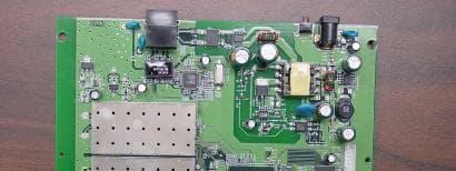
KA349WAN2
Sep 13, 2005HIGH CAPACITY WIRELESS BRIDGING/ROUTING SYSTEM
Equipment Class
TNB - Licensed Non-Broadcast Station Transmitter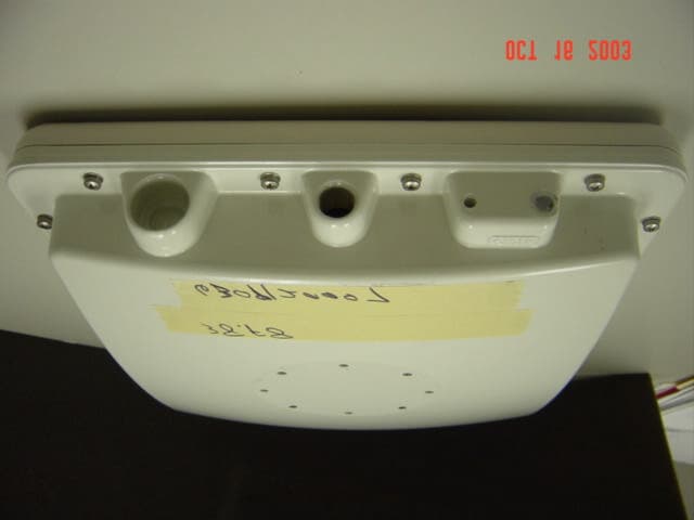
KA358WAN1
Oct 22, 2003DIGITAL TRANSCEIVER SYSTEM
Equipment Class
DXX - Part 15 Low Power Communication Device Transmitter