KA349WAN3Outdoor Broadband Wireless Radio
Solectek Corporation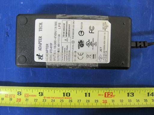
Click to zoom
Application Details
- Equipment Class
- TNB - Licensed Non-Broadcast Station Transmitter
- Date of Grant
- Aug 13, 2014
- Application Purpose
- Original Equipment
- Date of Application
- Aug 13, 2014
- Equipment Note
- Outdoor Broadband Wireless Radio
- Frequency Range
- 4950.00000000 - 4980.00000000
- Company
- Solectek Corporation
- Country
- United States
Documents & Files
Document Text
Text extracted from the exhibit documents filed with the FCC. Open a document above to read the original.
Users Manual
1 SkyWay ® Excel PTP Series User’s Guide v1.6 Part Number: 1514001 Copyright 2008-2009, Solectek Corp. All rights reserved. 1. Introduction Congratulations on your pu rchase of Solectek’s SkyWay Excel Series PTP Radio System, a feature rich, best-in-class wireless solution. This User’s Guide will describe the operation of your SkyWay unit in detail. S YSTEM F EATURES • Field proven, MIMO-OFDM modulation allowing high capacity, near line-of-sight deployment and st rong immunity to multi-path. • Power over Ethernet (PoE) fo r simplified cable routing. • Integrated antenna/radio simplifies installation and eliminates lossy RF coax runs. • Frame aggregation for enhanced data throughput. • Line speed QoS packet inspection prioritizes latency sensitive, real-time data. • Intuitive Web based user interface and Telnet CLI. KIT CONTENTS • SkyWay Radio (2) • External antennas & RF Cables (2 sets) 1 • +48VDC AC-DC Power Supply (2) • Power over Ethernet (PoE) injector (2) • Pre-assembled, two-axis mast mounting kit (2) • Cat5 weatherproofing feedthrough (2) • Coax/grommet seals • Documentation CD • Warranty and Compliance Card. NOTE: The requisite Cat5 Ethernet cables are not included in the package. Please contact Solectek for inform ation on available outdoor grade shielded Ethernet cables. Management Platform Requirements a) For GUI/Telnet management: Pentium IV (or later) computer; Windows XP SP2; Inte rnet Explorer v7.0. b) For SNMP monitoring: SNMP v2c co mpatible SNMP manager, running on appropriate PC/Server platform. 1 For external antenna model, only 2 2. Installation Outline This section summarizes the steps needed to properly configure and install the SkyWay Excel Radio. As the back ground and guidelines for much of the radio installation process are well covered in many in-depth publications and training classes, only those steps that uniquely relate to the SkyWay product are covered in this User Guide. A. System Design RF Design and Site Survey IP Network Design B. Unit Preparation Unit connection (Section 3) Initial Configuration (Sections 4-6) Bench testing (Section 7) C. Site Preparation Selection of unit mounting location Cable routing Preparation of mast and other supporting structures D. Installation Mounting (Section 8) Spectrum Analysis (Section 9) Antenna alignment (Section 10) E. Verification Link status + metrics (Section 11) Ping connectivity Performance testing Reliability monitoring F. Optimization RF channel tuning Data rate tuning QoS (Section 12) G. Management + Maintenance VLAN (Section 13) Telnet (Section 14) SNMP (Section 15) Network Time (Section 16) Password Management (Section 17) Software upgrades (Section 18) Reboot (Section 19) H. Troubleshooting Event Log (Section 20-21) Diagnostics (Section 22) 3. System Connection A. P ORT D ESCRIPTIONS SkyWay Excel has the following access ports: • (1) 10/100 Ethernet + Power Connector: RJ45 jack • (2) RF Ports: N type, female (connectorized unit only) The RJ45 connector is accessed at the bottom of the unit, through a multi-piece waterproofing feedthrough. If included, the two RF Ports are accessed on the top of the unit. Unit Top B. C ONNECTING THE S KY W AY U NIT Using the diagram below as a guide, ca ble your SkyWay test system using a PC or Laptop and a pair of Cat5 ca bles. An auto-MDIX feature eliminates the need for cross-over cables. To Radio To Network +48V in Cat5 Cat5 AC/DC PSU Po wer In jector PC / Laptop 3 C. L OG I NTO THE HTTP M ANAGEMENT S YSTEM • Open networking properties in your Windows OS. Find the TCP/IP setup window of your wired Ethernet adapter. Set the IP addresses to the following values. Ethernet’s IP Address: 192.168.1.1 Subnet Mask: 255.255.255.0 • Open a Web Browser on the Test PC • At the URL line, type in the following: http://192.168.1.100 to access the login prompt fo r a Slave unit, or http://192.168.1.200 to access a Master unit. • The username is admin and the default password is admin . Click OK and you will see the Main Status screen as shown below: 4 4. Initial Configuration A. IP Configuration Navigate to Configuration -> Basic to access the Basic Configuration screen: System Name This is an optional description of the unit used to simplify the identification of a particular radio in the wireless network. This parameter is not related to the identification of the unit on your wired local area network. For security purposes, the System Name is not broadcast across the RF link. Name can be up to 32 characters long, and consist of all alphanumerics, plus the following symbols: @ (at sign) - (dash) . (period) ‘ (tick) _ (underscore). Name may not include spaces. LAN IP Configuration IP Address : IP address of the local unit. Subnet Mask : Subnet mask of the local unit. Default Gateway : Default gateway for the local unit. B. System Mode In each Excel PTP link, one radio must be configured a Master device and the other a Slave device. To verify co rrect configuration, navigate to Configuration -> Advanced and confirm the state of each radio: A change to the System Mode setting requires that the Submit button be pressed and the radio be restarted. C. Wireless Configuration Navigate to Configuration -> Wireless to access the Wireless Configuration screen: RF Network Name The wireless network name assigned to this PTP network. Both sides of the link must share the same RF Network Name. RF Network Name can be up to 32 characters long, and consist of all alphanumerics, plus the following symbols: @ (at sign) - (dash) . (period) ‘ (tick) _ (underscore). RF Network Name may not include spaces. Transmit Power This parameter sets the RF ou tput power of the radio. Increasing this value will extend the range of the PTP system. However, the maximum available power is limited by both the countr y of operation, and by the chosen RF modulation. 5 For example, in the US, the maximum operating power should be limited as follows: Modulation Max Output Power QAM64 17 dBm QAM16 20 dBm QPSK, BPSK 23 dBm Ba…
Text truncated - open the document above for the full version.
Cover Letter(s)
SCS-F18: Project and Product Certification Representative Authorization Letter Page 1 of 2 Rev 2.0 2206 Ringwood Avenue San Jose, CA 95131 Tel: 408-526-1188 Fax: 408-526-1088 Email: [email protected] Project and Product Certification Representative Authorization Letter Revision History Reason for Amendment (current / obsolete) From To Approved Date Initial Release (current) 1.0 1.0 Nov-14-2006 Revised wording (current) 1.0 2.0 Sept–25-2007 SCS-F18: Project and Product Certification Representative Authorization Letter Page 2 of 2 Rev 2.0 (Client’s Company Letterhead/log) 19-Apr-2010 To: SIEMIC, INC. 2206 Ringwood Avenue, San Jose, CA 95131 USA Dear Sir/Madam, Re: Project and Product Certification Representative Authorization Letter We, Solectek Corp. hereby authorize SIEMIC, INC. to act as a Certification Body for certifying for the following project(s): SkyWay Excel, 4900 series (FCC ID: KA349WAN3) We affirm that between SIEMIC and Solectek, any difference in understanding, including test plan, measurement methods, applicable standards and relevant procedures and processes have been resolved prior to commencement of testing activities. Sincerely, David Gell VP Engineering Solectek Corp San Diego, CA
Cover Letter(s)
SCS-F19: Confidentiality Request Letter Page 1 of 2 Rev 2.0 19-Apr-2010 To: Federal Communications Commission Authorization and Evaluation Division 7435 Oakland Mills Road Columbia, MD Subject: Permanent Confidentiality Request for FCC ID: KA349WAN3 We hereby request confidential treatment of information accompanying this application as outlined below: - Internal Photos - Block Diagram - Operational Description - Schematics - Bills of Materials The above materials contain trade secrets and proprietary information not customarily released to the public. The public disclosure of these materials may be harmful to the applicant and provide unjustified benefits to its competitors. In addition, due to the following considerations, we herby request confidential treatment to all internal photos: • The product is intended for deployment on secure/restricted access rooftops and building sides. These locations are not accessible to the public • The product is not user serviceable. Tamper-seals are applied to restrict access to the inside of the device • The photos contain technical and design information which we deem to be trade secrets and proprietary. If made public, the information might be used to the disadvantage of Solectek Corporation. • We attest that the request for confidentiality of internal photos satisfies the following requirement "3) Internal photos can also be held confidential if a non-consumer device is inaccessible to the general public, such as a device mounted on the top of a large tower (or in a fenced enclosure) that is only serviceable by the licensee or his designated technicians." SCS-F19: Confidentiality Request Letter Page 2 of 2 Rev 2.0 The applicant understands that pursuant to Section 0.457 & 0.459 of the Rules, disclosure of this application and all accompanying documentation will not be made before the date of the Grant for this application. Sincerely, David Gell VP Engineering Solectek Corp San Diego, CA
External Photos
Antenna: External Antenna with 29dBi gain Antenna: Integral Antenna with 23dbi gain Antenna: External Antenna with 10dBi antenna gain Power Over Ethernet Power Supply
Internal Photos
Main Board – Top Main Board – Bottom Board A – Top Board A – Bottom Radio Board – Top (with RF shield) Radio Board – Top (without RF shield) Radio Board – Bottom
RF Exposure Info
MPE CALCULATION For Solectek Corp– Outdoor Broadband Wireless Radio, Model: SkyWay Xl49 RF Exposure Requirements: 47 CFR §1.1307(b) RF Radiation Exposure Limits: 47 CFR §1.1310 RF Radiation Exposure Guidelines: FCC OST/OET Bulletin Number 65 EUT Frequency Band: 4945MHz ~4985MHzMHz Limits for General Population/Uncontrolled Exposure in the band of: 1500MHz – 100000MHz Power Density Limit: 1 mW/ cm 2 ; Equation: S = PG / 4πR 2 or R = √PG / 4πS Where, S = Power Density P = Power Input to Antenna G = Antenna Gain R = distance to the center of radiated antenna ______________________________________________________________________________________________________________________ Power = 19.97dBm, Typical Antenna Gain = 29dBi, MPE limit= 1mW/cm 2 By using equation R = √PG / 4πS R= 79.22cm Result The Above Result had shown that the minimum separation distance in order to meet MPE requirement is 80cm. Completed By: Choon Sian Ooi Date: May 03, 2010
Test Report
SOLECTEK CORP Outdoor Broadband Wireless Radio Model: SkyWay XL49 3 May 2010 Report No.: SL10032601-SOL-001rev 2.0 (This report supersedes: SL10032601-SOL-001rev 1.0) Modifications made to the product : None This Test Report is Issued Under the Authority of: Choon Sian Ooi Compliance Engineer Leslie Bai Director of Certification This test report may be reproduced in full only. Test result presented in this test report is applicable to the representative sample only. Title: RF Test Report of Solectek Corp Model : SkyWay XL49 To FCC 90Y 2009 & RSS 111 Issue 3.0 Serial# SL10032601-SOL-001rev 2.0 Issue Date 3 May 2010 Page 2 of 98 www.siemic.com Laboratory Introduction SIEMIC, headquartered in the heart of Silicon Valley, with superior facilities in US and Asia, is one of the leading independent testing and certification facilities providing customers with one-stop shop services for Compliance Testing and Global Certifications. In addition to testing and certification, SIEMIC provides initial design reviews and compliance management through out a project. Our extensive experience with China, Asia Pacific, North America, European, and international compliance requirements, assures the fastest, most cost effective way to attain regulatory compliance for the global markets. Accreditations for Conformity Assessment Country/Region Accreditation Body Scope USA FCC, A2LA EMC , RF/Wireless , Telecom Canada IC, A2LA, NIST EMC, RF/Wireless , Telecom Taiwan BSMI , NCC , NIST EMC, RF, Telecom , Safety Hong Kong OFTA , NIST RF/Wireless ,Telecom Australia NATA, NIST EMC, RF, Telecom , Safety Korea KCC/RRA, NIST EMI, EMS, RF , Telecom, Safety Japan VCCI, JATE, TELEC, RFT EMI, RF/Wireless, Telecom Mexico NOM, COFETEL, Caniety Safety, EMC , RF/Wireless, Telecom Europe A2LA, NIST EMC, RF, Telecom , Safety Accreditations for Product Certifications Country Accreditation Body Scope USA FCC TCB, NIST EMC , RF , Telecom Canada IC FCB , NIST EMC , RF , Telecom Singapore iDA, NIST EMC , RF , Telecom Title: RF Test Report of Solectek Corp Model : SkyWay XL49 To FCC 90Y 2009 & RSS 111 Issue 3.0 Serial# SL10032601-SOL-001rev 2.0 Issue Date 3 May 2010 Page 3 of 98 www.siemic.com This page has been left blank intentionally. Title: RF Test Report of Solectek Corp Model : SkyWay XL49 To FCC 90Y 2009 & RSS 111 Issue 3.0 Serial# SL10032601-SOL-001rev 2.0 Issue Date 3 May 2010 Page 4 of 98 www.siemic.com CONTENTS 1 EXECUTIVE SUMMARY & EUT INFORMATION ................................................................................................................ 6 2 TECHNICAL DETAILS...................................................................................................................................................... 7 3 MODIFICATION ............................................................................................................................................................... 8 4 TEST SUMMARY ............................................................................................................................................................. 9 5 MEASUREMENTS, EXAMINATION AND DERIVED RESULTS ......................................................................................... 10 ANNEX A. TEST INSTRUMENT & METHOD ............................................................................................................................ 73 ANNEX B EUT AND TEST SETUP PHOTOGRAPHS ............................................................................................................... 77 ANNEX C. TEST SETUP AND SUPPORTING EQUIPMENT ....................................................................................................... 77 ANNEX D USER MANUAL, BLOCK & CIRCUIT DIAGRAM ...................................................................................................... 81 ANNEX E. SIEMIC ACCREDITATION CERTIFICATES .............................................................................................................. 82 Title: RF Test Report of Solectek Corp Model : SkyWay XL49 To FCC 90Y 2009 & RSS 111 Issue 3.0 Serial# SL10032601-SOL-001rev 2.0 Issue Date 3 May 2010 Page 5 of 98 www.siemic.com This page has been left blank intentionally. Title: RF Test Report of Solectek Corp Model : SkyWay XL49 To FCC 90Y 2009 & RSS 111 Issue 3.0 Serial# SL10032601-SOL-001rev 2.0 Issue Date 3 May 2010 Page 6 of 98 www.siemic.com 1 Executive Summary & EUT information The purpose of this test programmed was to demonstrate compliance of the Solectek Corp, Model: Nano-UHF against the current Stipulated Standards. The Outdoor Broadband Wireless Radio have demonstrated compliance with the FCC 90Y 2009. The equipment under test radio operating frequency is 4945MHz to 4985MHz (10MHz) 4950MHz to 4980 MHz (20MHz) The test has demonstrated that this unit complies with stipulated standards. EUT Information EUT Description : System, a feature rich, best-in-class wireless solution. SYSTEM FEATURES • Field proven, MIMO-OFDM modulation allowing high capacity, near line-of-sight deployment and strong immunity to multi-path. • Power over Ethernet (PoE) for simplified cable routing. • Integrated antenna/radio simplifies installation and eliminates lossy RF coax runs. • Frame aggregation for enhanced data throughput. • Line speed QoS packet inspection prioritizes latency sensitive, realtime data. • Intuitive Web based user interface and Telnet CLI. KIT CONTENTS • SkyWay Radio (2) • External antennas & RF Cables (2 sets)1 • +48VDC AC-DC Power Supply (2) • Power over Ethernet (PoE) injector (2) • Pre-assembled, two-axis mast mounting kit (2) • Cat5 weatherproofing feedthrough (2) • Coax/grommet seals • Documentation CD • Warranty and Compliance Card. Model No : SkyWay XL49 Input Power : 120Vac 60Hz Classification Per Stipulated Test Standard : Licensed Non-Broadcast Station Transmitter Title: RF Test Report of Solectek Corp Model : SkyWay XL49 To FCC 90Y 2009 & RSS 111 Issue 3.0 Serial# SL10032601-SOL-001…
Text truncated - open the document above for the full version.
Test Setup Photos
Radiated Emission View (>30MHz) Radiated Emission View (< 30Mhz)
Contact Information
Applicant
Eric Lee(President)
Test Firm
SIEMIC LaboratoriesLeslie Bai
Technical Specifications
| # | Rule Parts | Frequency Range | Power Output | Emission | Tolerance |
|---|---|---|---|---|---|
| 2 | 90Y | 4.95 GHz - 4.98 GHz | 99.00 mW | 16M5W7D | 4.833 ppm |
Other Applications from Solectek Corporation
KA358MRS1
Jan 31, 2008Wireless Telemetry Transceiver
Equipment Class
DTS - Digital Transmission System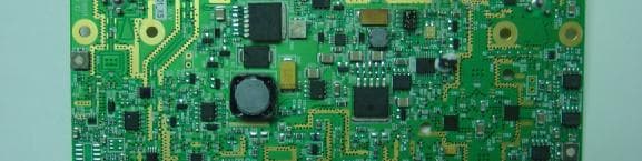
KA349WAN1
Sep 13, 2005HIGH CAPACITY WIRELESS BRIDGING/ROUTING SYSTEM
Equipment Class
TNB - Licensed Non-Broadcast Station Transmitter
KA349WAN2
Sep 13, 2005HIGH CAPACITY WIRELESS BRIDGING/ROUTING SYSTEM
Equipment Class
TNB - Licensed Non-Broadcast Station Transmitter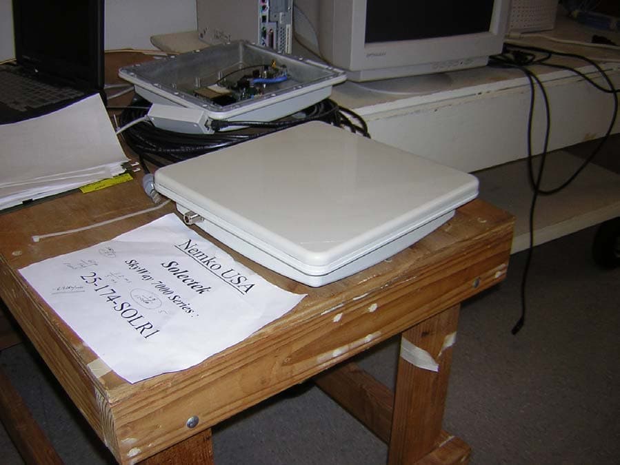
KA358WAN2
Jun 13, 2005Ethernet Bridge / Transceiver
Equipment Class
DTS - Digital Transmission System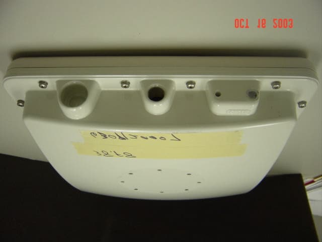
KA358WAN1
Oct 22, 2003DIGITAL TRANSCEIVER SYSTEM
Equipment Class
DXX - Part 15 Low Power Communication Device Transmitter