KA358MRS1Wireless Telemetry Transceiver
Solectek Corporation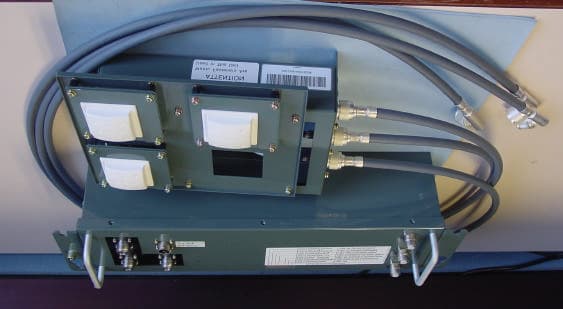
Click to zoom
Application Details
- Equipment Class
- DTS - Digital Transmission System
- Date of Grant
- Jan 31, 2008
- Application Purpose
- Original Equipment
- Date of Application
- Jan 31, 2008
- Equipment Note
- Wireless Telemetry Transceiver
- Frequency Range
- 5745.00000000 - 5805.00000000
- Company
- Solectek Corporation
- Country
- United States
Documents & Files
Document Text
Text extracted from the exhibit documents filed with the FCC. Open a document above to read the original.
Users Manual
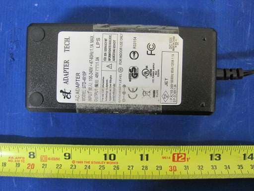
This document is Solectek CONFIDENTIAL and may not be reproduced without written permission. V1.5 Document Number: SYSFS Reviewed By: SYSTEM Release Date: 1-DEC-07 Koito MRS User Guide v1.5 This document is Solectek CONFIDENTIAL and may not be reproduced without written permission. V1.5 1. Introduction For the Phase II release, the Configuration of the MRS boardset can be changed in three ways: HTTP GUI, Telnet and Configuration File. 1. The GUI is functional, though per Solectek schedule, is not completely functional. 2. Telnet may be used to work with the commands listed in this document. 3. The Configuration File may be offloaded, modified and re-stored on the MRS. 2. Unit Power The MRS boardset is intended to be powered via the 2pin, +48V connector on Minotaur. The Solectek Base Station is to be powered via PoE, supplied by the included Power Supply/Injector and connected into the RJ45 Minotaur connector 3. Unit Access Both HTTP and Telnet access is password protected. Default access is as follows: Login: Root Password: Solectek 4. Unit Defaults MRS Boardset Solectek Base Station Network Mode Bridge Bridge Ethernet IP Address 172.21.0.100/255.255.0.0 172.21.0.10/255.255.0.0 RF IP Address 192.168.1.x/255.255.255.0 192.168.1.x/255.255.255.0 RF Mode Client Access Point SSID Koito_2 Koito_2 Encryption Open Open RF Bandwidth 20 MHz 20 MHz 5. Telnet Any Telnet client can be used to access the MRS and Base Station devices. Access is per login/password above. Once logged in, configuration can be adjusted by two methods: (a) direct commands, or by (b) modifying the configuration file. 5.1. Direct Commands set_config The set_config can be used to change (or add) a configuration variable. On in the Telnet shell, the command may be invoked as: This document is Solectek CONFIDENTIAL and may not be reproduced without written permission. V1.5 set_config VARIABLE VALUE eg. set_config ENET0_IPADDR 10.20.20.7 (Set the ENET0_IPADDR). set_config DEV_MODE ap (set the device operation mode to AP). IMPORTANT: All set_config commands should be followed by a save_config command which stores the changes to permanent Flash memory. A reboot is also required for most command to take effect. show_config You may use the show_config command to display the value of a configuration variable. eg. show_config ROUTER_TYPE 5.2. Configuration File Within the MRS software system, there are two files that hold configuration information. Both are accessible by Telnet: • /etc/shadow - has user name and passwords for console and telnet (and ssh) login. (This file does not hold the password for the GUI login) • /etc/solectek/CONFIG_VARS - This file holds all the configuration information for Networking (such as IP addresses, netmasks etc.), WIFI configuration, Product Operation mode etc. Remember that any method you use to modify these files, require the command save_config when you are done with the changes. The file CONFIG_VARS contains information on the product configuration. This file has a very simple format: VARIABLE1=VALUE1 VARIABLE2=VALUE2 Changing the VALUE of a VARIABLE will change them in the current CONFIG_VARS file, but not in the flash. The file can be changed by: uploading a version of the file to a PC, edit it, and download it back to the device. Save it, and then reboot. There are two methods to accomplish this: • ftp - ftpput is used to send a file from the MRS device to a remote system. ftpget is used to get a file from a system. The commands look as follows: ftpput -u username -p password local-file remote-file ftpget -u username -p password local-file remote-file This document is Solectek CONFIDENTIAL and may not be reproduced without written permission. V1.5 • http - Can be used only to download a file. The command is: wget http://ip-address/path-to-file 6. Configuration Parameters Note: Parameters are case sensitive Note: Parameter format below is correct for CONFIG_VARS file usage. When used with set_config, the ‘=’ is replaced by a space. • ENET0_IPADDR=aa.bb.cc.dd - IP address of the Ethernet Interface - Used as the Bridge address when the system is operating in Bridge mode. • ENET0_NETMASK=aa.bb.cc.dd - Netmask for the interface • ENET0_BROADCASAT=aa.bb.cc.dd - The broadcast address of the interface • ENET0_MAC=aa:bb:cc:dd:ee:ff - The mac address (This may go-away based on manufacturing). Currently, when the system boots up, this MAC address is set on the Ethernet Interface. • WIFI_IPADDR=aa.bb.cc.dd - The WIFI IP address - Can be ignored if the system is a Bridge • WIFI_NETMASK=aa.bb.cc.dd - Netmask for the interface • WIFI_BROADCAST=aa.bb.cc.dd - Broadcast address of the interface • DEFAULT_GATEWAY=aa.bb.cc.dd - The default router gateway • ESSID - ESSID of the wireless interface - If the device is an AP, then it will advertise the ESSID, while if it is a client, then it will connect to this ESSID • DEV_MODE=ap|client - The device mode, can either be "ap" or "client" • ROUTER_TYPE=bridge|router - The routing method can be "bridge" or "router". If bridging is used, then it will use the information of the Ethernet interface and apply it to the bridge interface. • WIFI_CWMMODE=0|1|2 - 0 = static 20Mhz channel, 1 = dynamic 20/40 Mhz, 2 = 40 Mhz Channel. System must be set to 0. • WIFI_ENC=open|shared|ieee8021x - open is WEP (static key), shared WPA2 with either a passphrase or passkey (128 bits). • WIFI_WEP_KEY=key - 10 digit or 26 digit hex key (for 40+24 or 104+24) WEP • WIFI_PASSPHRASE=pass-phrase - 8 to 32 characters - This is used when WIFI_ENC=shared. If present, this will be used instead of WIFI_PSK (below) This document is Solectek CONFIDENTIAL and may not be reproduced without written permission. V1.5 • WIFI_PSK=32 hex digits PSK - Used in shared mode • RADIUS_SERVER=a.b.c.d - IP address of radius server. Used when WIFI_ENC=ieee8021x. • RADIUS_SECRET=secret - Secret shared with the radius server • ADMIN_NAME=admin - For HTTP login request for the GUI • ADMIN_PASS=password - For the HTTP login …
Text truncated - open the document above for the full version.
Cover Letter(s)
Nemko Canada Inc 303 River Road Ottawa, Ontario, Canada K1V 1H2 Attn: Director of Certification RE: FCC ID#: KA358MRS1 Authority to Act as Agent On our behalf, I appoint Nemko USA, located at 11696 Sorrento Valley Road, San Diego, CA, to act as our agent in the preparation of this application for equipment certification. I certify that submitted documents properly describe the device or system for which equipment certification is sought. I also certify that each unit manufactured, imported or marketed, as defined in the Federal Communications Commission’s regulations will have affixed to it a label identical to that submitted for approval with this application. For instances where our authorized agent signs the application for certification on our behalf, I acknowledge that all responsibility for complying with the terms and conditions for certification, as specified by Nemko Canada Inc, still resides with Solectek Corporation, located at 6370 Nancy Ridge Drive, San Diego, CA. Dated this 14 Day of November 20 07 Agency agreement expiration date: 14-Nov-08 By: David Gell Signature Printed Title: VP Engineering On behalf of : Solectek Corporation Telephone: 858-450-1220
Cover Letter(s)
14-Nov-07 Solectek Corporation 6370 Nancy Ridge Drive Suite 109 San Diego, CA 92121 Nemko 11696 Sorrento Valley Rd. San Diego CA, 92121 USA Re: Request of Confidentiality for FCC ID#: KA358MRS1 Pursuant to Sections 0.457(d)(I)(ii) and 0.459 of the Commission’s Rules, the Applicant hereby requests confidential treatment of information accompanying as outlined below: Schematics, Parts List, Operating Description, Block Diagrams The above materials contain trade secrets and proprietary information not customarily released to the public. The public disclosure of these matters might be harmful to the Applicant and provide unjustified benefits to its competitors. The Applicant understands that pursuant to Rule 0.457(d)(I)(ii), disclosure of this Application and all accompanying documentation will not be made before the date of the Grant for this Application. Sincerely, David Gell VP Engineering Solectek Corporation
ID Label/Location Info
Solectek Corporation Model No.: 1531000 FCC ID: KA358MRS1 * This device complies with Part 15 of the FCC Rules. Operation is subject to the following two conditions: (1) This device may not cause harmful interference, and (2) This device must accept any interference received, including interference that may cause undesired operation. Made in Japan
RF Exposure Info
Prediction of MPE limit at a given distance Equation from page 18 of OET Bulletin 65, Edition 97-01where: S = power density P = power input to the antennaG = power gain of the antenna in the direction of interest relative to an isotropic radi a R = distance to the center of radiation of the antenna Maximum peak output power at antenna input terminal: 17.10 (dBm) Maximum peak output power at antenna input terminal: 51 (mW) Antenna gain(typical): 3 (dBi) Maximum antenna gain: 1.995 (numeric) Prediction distance: 20 (cm) Sourse Based Time Average Duty Cycle: 100 (%) Prediction frequency: 5745 (MHz) MPE limit for uncontrolled exposure at prediction frequency: 1.000 (mW/cm^2) Power density at prediction frequency: 0.0204 (mW/cm^2) Margin of Compliance: 16.9 2 4 R PG S π =
Test Report
Nemko USA, Inc. 11696 Sorrento Valley Rd., Suite F San Diego, CA 92121-1024 Phone (858) 755-5525 Fax (858) 452-1810 FCC Part 15 Subpart C, 15.247 : 24/01/2008 Test Report: 2007 118189 MIMO FCC Project number: 8189-1 Applicant: Solectek Corporation 6370 Nancy Ridge Road Suite 109 San Diego, CA 92121-3212 Equipment Under Test (EUT): 5.8GHz Broadband Wireless Communication Platform Model: MRS FCC ID: KA358MRS1 In Accordance With: FCC Part 15 Subpart C, 15.247 Tested By: Nemko USA Inc. 11696 Sorrento Valley Road, Suite F San Diego, CA 92121 Authorized By: Alan Laudani, RF/EMC Test Specialist Date: January 2, 2008 Total Number of Pages: 63 Nemko USA, Inc. 11696 Sorrento Valley Road, Suite F, San Diego, CA 92121 Phone (858) 755-5525 Fax (858) 452-1810 Report Number: 2007 118189 MIMO FCC FCC ID: KA358MRS1 Specification: FCC Part 15 Subpart C, 15.247 Page 2 of 63 2.1. Section 1. Summary of Test Results General All measurements are traceable to national standards These tests were conducted on a sample of the equipment for the purpose of demonstrating compliance with Part 15; Subpart C. Radiated tests were conducted is accordance with ANSI C63.4-2003. Radiated emissions are made on an open area test site. A description of the test facility is on file with the FCC. The assessment summary is as follows: Apparatus Assessed: 5.8GHz Broadband Wireless Communication Platform Model MRS Specification: FCC Part 15 Subpart C, 15.247 Date Received in Laboratory: October 17, 2007 Compliance Status: Complies Exclusions: None Non-compliances: None Report Release History: REVISION DATE COMMENTS - Jan. 2, 2008 Prepared By: Ferdinand S. Custodio - Jan. 2, 2008 Initial Release: Alan Laudani Nemko USA, Inc. 11696 Sorrento Valley Road, Suite F, San Diego, CA 92121 Phone (858) 755-5525 Fax (858) 452-1810 Report Number: 2007 118189 MIMO FCC FCC ID: KA358MRS1 Specification: FCC Part 15 Subpart C, 15.247 Page 3 of 63 Note that the results contained in this report relate only to the items tested and were obtained in the period between the date of initial receipt of samples and the date of issue of the report. This test report has been completed in accordance with the requirements of ISO/IEC 17025. Nemko USA Inc. authorizes the applicant to reproduce this report provided it is reproduced in its entirety and for use by the company’s employees only. Any use which a third party makes of this report, or any reliance on or decisions to be made based on it, are the responsibility of such third parties. Nemko USA Inc. accepts no responsibility for damages, if any, suffered by any third party as a result of decisions made or actions based on this report. TESTED BY: ___________________________________ Date: Jan. 2, 2008 Ferdinand S. Custodio, EMC Test Engineer Nemko USA, Inc. 11696 Sorrento Valley Road, Suite F, San Diego, CA 92121 Phone (858) 755-5525 Fax (858) 452-1810 Report Number: 2007 118189 MIMO FCC FCC ID: KA358MRS1 Specification: FCC Part 15 Subpart C, 15.247 Page 4 of 63 TABLE OF CONTENTS 2.1. Section 1. Summary of Test Results.......................................................................2 Section 2: Equipment Under Test..........................................................................................5 2.1 Product Identification....................................................................................................5 2.2 Samples Submitted for Assessment..........................................................................5 2.4 Theory of Operation......................................................................................................6 2.5 Technical Specifications of the EUT..........................................................................6 2.5 Block Diagram................................................................................................................7 2.5 List of Accessories........................................................................................................8 Section 3: Test Conditions......................................................................................................9 3.1 Specifications.................................................................................................................9 3.2 Deviations From Laboratory Test Procedures..........................................................9 3.3 Test Environment..........................................................................................................9 3.4 Test Equipment............................................................................................................10 Section 4: Observations.........................................................................................................11 4.1 Modifications Performed During Assessment.........................................................11 4.2 Record Of Technical Judgements............................................................................11 4.3 EUT Parameters Affecting Compliance...................................................................11 4.4 Test Deleted.................................................................................................................11 4.5 Additional Observations.............................................................................................11 Section 5: Results Summary.................................................................................................12 5.1 FCC Part 15 Subpart C and Subpart E: Test Results...........................................12 Appendix A: Test Results......................................................................................................13 Clause 15.209(a) Radiated Emissions (General Requirements)........................................13 Bandedge Measurements..........................................................................................................16 Clause 15.247(d) Spurious Emissions (RF Antenna Conducted Test)...........................…
Text truncated - open the document above for the full version.
Contact Information
Applicant
Eric Lee(President)
Technical Contact
Solectek CorporationDavid Gell
[email protected]858-450-1220
6370 Nancy Ridge Drive, Suite 109 · San Diego, California · United States
Non-Technical Contact
Solectek CorporationDavid Gell
[email protected]858-450-1220
Test Firm
Nemko USA, Inc.Rhonda Saxon
Technical Specifications
| # | Rule Parts | Frequency Range | Power Output |
|---|---|---|---|
| 1 | 15C | 5.75 GHz - 5.80 GHz | 51.40 mW |
Other Applications from Solectek Corporation
KA349WAN3
Aug 13, 2014Outdoor Broadband Wireless Radio
Equipment Class
TNB - Licensed Non-Broadcast Station Transmitter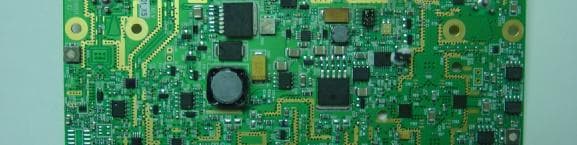
KA349WAN1
Sep 13, 2005HIGH CAPACITY WIRELESS BRIDGING/ROUTING SYSTEM
Equipment Class
TNB - Licensed Non-Broadcast Station Transmitter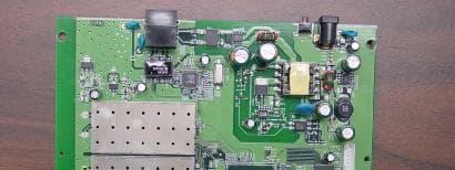
KA349WAN2
Sep 13, 2005HIGH CAPACITY WIRELESS BRIDGING/ROUTING SYSTEM
Equipment Class
TNB - Licensed Non-Broadcast Station Transmitter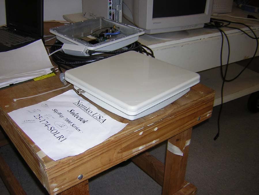
KA358WAN2
Jun 13, 2005Ethernet Bridge / Transceiver
Equipment Class
DTS - Digital Transmission System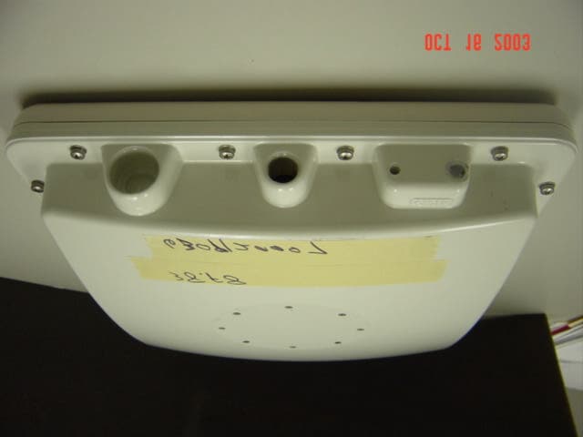
KA358WAN1
Oct 22, 2003DIGITAL TRANSCEIVER SYSTEM
Equipment Class
DXX - Part 15 Low Power Communication Device Transmitter