KBRASTU51Keyless Entry System Transmitter
Marelli Corporation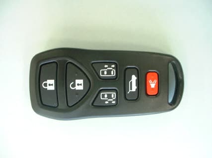
Click to zoom
Application Details
- Equipment Class
- DSR - Part 15 Remote Control/Security Device Transceiver
- Date of Grant
- Dec 09, 2002
- Application Purpose
- Original Equipment
- Date of Application
- Dec 09, 2002
- Equipment Note
- Keyless Entry System Transmitter
- Frequency Range
- 315.00000000 - 315.00000000
- Company
- Marelli Corporation
- Country
- Japan
Documents & Files
Document Text
Text extracted from the exhibit documents filed with the FCC. Open a document above to read the original.
Users Manual
9.USER OPERATION INSTRUCTION(DRAFT) MULTI-REMOTE CONTROL SYSTEM It is possible to lock/unlock all doors and activate the panic alarm by using the remote controller (transmitter) from outside the vehicle. Before locking the doors, make sure the keys is not left in the vehicle. The remote controller can operate at a distance of approximately 33 ft(10m) from the vehicle. (The Effective distance depends upon the conditions around the vehicle.) As many as four remote controllers can be used with one vehicle. For information concerning the Purchace and use of additional remote controllers, contact your NISSAN dealer. The multi-remote controller will not function when: -the battery is dead. -the distance between the vehicle and the remote controller is over 33ft(10m). The panic alarm will not activate when the key is in the ignition switch. ! CAUTION The following conditions or occurrence will damage the remote controller. -Do not allow the remote controller to become wet. -Do not drop the remote controller. -Do not strike the remote controller sharply against another object. -Do nou place the remote controller for an extended period in an area where temperature exceed 140 degree F(60 degree C). If multi-remote controller is lost or stolen,NISSAN recommends erasing the ID code of that controller. This will prevent the controller from unauthorized use to unlock the vehicle. For information regarding the eracing procedure, please contact an authorized NISSAN dealer. HOW TO USE MULTI-REMOTE CONTROL SYSTEM Setting hazard and horn chirp mode This vehicle is set in hazard and horn chirp mode when you first receive the vehicle. In hazard and horn chirp mode, when the LOCK button is pushed, the hazard indicator flashes twice horn chirps once. When the UNLOCK button is pushed hazard indicator flashes once. If hazard and horn chirp mode is not necessary, you can switch to normal mode by following the switching procedure. In normal mode, when the LOCK button is pushed, the hazard indicator flashes twice. When the UNLOCK button is pushed, neither the hazard indicator nor the horn operates. -Switching procedure Push the LOCK and UNLOCK buttons on the multi-remote controller simultaneously for more than 2 seconds to switch from one mode to the other. When pushing the buttons to set normal mode, the hazard indicator flashes 3 times. When pushing the buttons to set hazard and horn chirp mode, the hazard indicator flashes once and the horn chirp once. Locking the doors 1. Remove the ignition key. (*1) 2. Close all doors. (*2) 3. Push the Lock button on the multi-remote controller. 4. All of the doors will lock. All of the doors will lock when the LOCK button on the multi-remote controller is pushed even Though a door remains open and/or the ignition key is in the ON position. 5.The hazard indicator flashes twice and the horn chirp once. When the LOCK button is pushed with all doors locked, the hazard indicator flashes twice and the Horn chirps once as a reminder that the doors are already locked. *1:Doors lock with the remote controller while a key is in the ignition switch. However, the panic alarm will not activate when the key is in the ignition switch. *2: Doors lock with the remote controller while any door is open. However, hazard and horn chirp mode will not function. Unlocking doors 1. Push the UNLOCK button on the multi-remote completely closed. -Only the driver door unlocks. -The hazard indicator flashes once if all doors are completely closed. -The interior light turns on and the light timer activates for 30 seconds when the interior light switch of the vehicle is in the center position. 2.Push the UNLOCK button on the multi-remote controller again within 5 seconds. -All doors unlock. -The hazard indicator flashes once if all doors completely closed. The interior light can be turned off without waiting for 30 seconds by turning the ignition switch to The on position or by locking the doors with the multi-remote controller. Opening the slide door(right and left) 1. Push the slide door button on the multi-remote controller for longer than 0.5 second with the key removed from the key cylinder. 2.The rear gate opens. Opening the rear gate 2. Push the rear gate button on the multi-remote controller for longer than 0.5 second with the key Removed from the key cylinder. 3. The rear gate opens. The rear gate will not open when the rear gate cancel lever is in the CANCEL position. It can be opened only with the key. See “Rear gate” later in this section for cancel lever. Using the panic alarm If you are near your vehicle and feel threatended, you may activate the alarm to call attentions as follows: 1. Push the PANIC button on the remote controller for longer than 0.5 seconds. 2. The theft warning alarm and head lights will stay on for 30 seconds. 3. The panic alarm stops then; -It has run for 30 seconds, or -The LOCK or the UNLOCK button is pushed on the multi-remote controller for longer than 0.5 seconds. BATTERY REPLACEMENT Replace the battery as follows. 1. Open the lid using a suitable tool. 2. Replace the battery with a new one. -Recommended battery:CR2025 or equivalent. -Make sure that the + side face the bottom case. 3. Close the lid securely. 4. Push the remote controller button two or three times to check its operation. See your NISSAN dealer if you need any assistance for replacement. If the battery is removed for any reason other than replacement, perform step4 above. -An improperly disposed battery can harm environment. Always confirm local regulations for battery disposal. -The remote controller is water-proof, however, if it get wet, immediately wipe completely dry. -When changing batteries, do not let dust or oil get in the controller. FCC Notice: Changes or modifications not expressly approved by the manufacturer for compliance could void the User’s authority to operate the equipment. This device complies with Part 15 of the FCC Rules and Regulation and the Standard RSS-210 of Industry Canada…
Text truncated - open the document above for the full version.
External Photos
CalsonicKansei Corp. Transmitter of Keyless Entry System <FCC ID: KBRASTU51> <External photos> Front view CalsonicKansei Corp. Transmitter of Keyless Entry System <FCC ID: KBRASTU51> Rear view
ID Label/Location Info
3.Labelling of equipment The labeling is molded on the back surface of the transmitter as shown bellow. FCC ID :KBRASTU51 MODEL NO. :ASTU51 IC : 2111B-ASTU51 MANUFACTURER : CalsonicKansei Corp.
Internal Photos
CalsonicKansei Corp. Transmitter of Keyless Entry System <FCC ID: KBRASTU51> <Internal photos> Inside view CalsonicKansei Corp. Transmitter of Keyless Entry System <FCC ID: KBRASTU51> Inside view CalsonicKansei Corp. Transmitter of Keyless Entry System <FCC ID: KBRASTU51> Inside view CalsonicKansei Corp. Transmitter of Keyless Entry System <FCC ID: KBRASTU51> Circuit board <Front> CalsonicKansei Corp. Transmitter of Keyless Entry System <FCC ID: KBRASTU51> Circuit board <Rear >
Operational Description
1. GENERAL TECHNICAL DESCRIPTION 1-1. INTENDED USE AND OPERATION INSTRUCTIONS This equipment constitutes a keyless entry system comprising a portable transmitter and a control unit including receiver installed in a inside of the vehicle. This system is a radio frequency apparatus which distantly controls the locking and unlocking of motor vehicle door locks, unlock and trunk lid by operating a portable transmitter with six control buttons(six push button switches). The transmitter is a portable device and the control unit including the receiver which has an integral receiving antenna is a mobile device installed behind the instrument panel of the vehicle. The construction of the system is given in section1-2. The transmitter is activated by loading a battery cell in it. The Specification of operation is shown below. By pressing the “LOCK” or “UNLOCK” or “POWER SLIDE DOOR RIGHT” or “POWER SLIDE LEFT” or “REAR GATE” or “PANIC” button for least 13 milliseconds, the duration requird for the transmitter and the receiver to recognize the state of the switch as ON or OFF, the vehicle’s door lock actuators are energized, and flash the hazard lamps for indicator purpose. By pressing one of the buttons, the radiation occurs in the form of coded signals that are received by the control unit installed in the vehicle. The control unit wakes-up,then compares the received ID code with the pre-stored ID code in its non-volatile memory, then activates the door lock actuators upon coincidence of both codes. The ID signal is consisted by unique ID portion and function portion which directs the control units “LOCK” or “UNLOCK” or “POWER SLIDE DOOR RIGHT” or “POWER SLIDE LEFT” or “REAR GATE” or “PANIC” status. To press one of the buttons for at least 13 milliseconds,the transmitter about after 26 milliseconds, radiatesA+B+B coded signal to be received by the control unit installed in the vehicle to corresponding vehicle parts actuated,where A is a wake up signal and B is a word signal(see Timing Diagram below). Regarding “PANIC” it is required to actuate corresponding function on the vehicle, to press continuously at least 0.5 seconds. To press any buttons continuously up to 25 seconds, the transmitter continuously send word signal B. Button (Switch) ON OFF Transmit data A B 26mS B 44.8mS 1-2. CONSTRUCTION OF KEYLESS ENTRY SYSTEM The construction of the system is shown below. 1-3. TIMING DIAGRAM (1) To press one of the buttons for at least 13 milliseconds,the transmitter about after 26 milliseconds, radiatesA+B+B coded signal The timing diagram of the system is shown below. Transmitter Antenna Controller(receiver) This equipment is not included in this application for radio type approval. Each singal of vehicle Figure 1-1:system construction Button (Switch) ON OFF Transmit data A B B >25sec ......................... Button (Switch) ON OFF Transmit data A B 26mS B 44.8mS B 44.8mS (2) The word signal B is consisted by six portions, which are preamble(a), header(b), encrypt(c), serial number(d), function code(e) and verify code(f). construction of Word signal B (3) The signal of wake up A and preamble(a) are consisted by a element pulse of on time 400 microseconds(TE)and off time 800 microsecond(2TE), duty 1/3 pulse. The wake up signal A is consisted by 84 element pulses and a 102.4 milliseconds dead time. The preamble(a) is consisted by 7 element pulses. The header(b) is consisted by a 4 milliseconds on and 4milliseconds off long pulse. (4) The encrypt(c) is 32 bit, the serial number(d) is 28 bit, function code(e) is 4 bit and verify code(f) is 2 bit pluses are used, where data 1 bit is consisted by one single high or low signal, for example, TE high or 2TE low means “1”, 2TE high or TE low means “0”. preamble header encrypt Serial number Function code Verify code Transmit data 102.4mS dead time TE 2TE 84pulses TE 2TE 6pulses 4mS 4mS header preamble Serial number encrypt 32bit 28bit 4bit 2bit Function code verify code (5) To press of one of the “LOCK”,“UNLOCK”,“POWER SLIDE DOOR RIGHT”,“POWER SLIDE LEFT”, “REAR GATE”or “PANIC” buttonsaas mentioned (1). , the transmitter transmits all same signal except function code(e). the button function is characterized by the fuction code(e), which is unique for each buttons. (6) To press “UNLOCK” button once, the driver door of the vehicle is unlocked, to press twice within 1.5 seconds, all doors unlocked. (7) To press any button for longer period, the transmit of word cord B will be continued but will cease it within 25 seconds. (8) Regarding “PANIC” button, it makes sound the alarm and the head lights of the vehicle for approximately 30 seconds, during sound alarm period, to press “PANIC” button again it stops. (9) To press the “LOCK” and “UNLOCK” buttons simultaneously at least 2 seconds, it switches one mode which deactivate the horn chirp and the hazard flashing as the indicator on locking, and other mode which activate them. The transmitter and receiver communication is made on frequency f=315MHz, and the modulation is AM, corresponding to binary digit 0 and 1. 2.TECHNICAL SPECIFICATIONS 2-1.Transmitter specifications -Model number : ASTU51 -Power source : CR2025(Lithium battery 3V) -Nominal voltage : 2.85V/3.0V(On load/Off load) -Center frequency : 315MHz -Number of channels : 1 -Emission designator : H1D -Type of antenna : P.C.B pattern antenna -Method of frequency generation : SAW -Frequency multiplication : 1 2-2.Transmitter’s characteristics -Maximum output field strength : 6000uV/m(@3m) -maximum spurious radiation : FCC rules Part15;15.209 -Frequency tolerance : 315MHz+65,-40kHz
Test Report
Test report No. : 23CE0012-HO Page : 2 of 14 Issued date : November 14, 2002 FCC ID : KBRASTU51 A-Pex International Co., Ltd.EMC Head Office Division. CONTENTS PAGE SECTION 1: Client information 3 SECTION 2: Equipment under test (E.U.T.) 3 SECTION 3: Test specification, procedures and results 4 SECTION 4: Operation of E.U.T. during testing 6 SECTION 5: Radiated EmissionFundamental and Spurious Emission 7 APPENDIX 1: Photographs of test setup 8 APPENDIX 2: Test instruments 8 APPENDIX 3: Data of EMI test 8 4383-326 Asama-cho, Ise-shi, Mie-ken 516-0021 JAPAN Telephone: +81 596 24 8116 Facsimile: +81 596 24 8124 Test report No. : 23CE0012-HO Page : 3 of 14 Issued date : November 14, 2002 FCC ID : KBRASTU51 A-Pex International Co., Ltd.EMC Head Office Division. SECTION 1: Client information Company name : CalsonicKansei Corp. Brand name : NISSAN Address : 540-7 Kyoei, Kodama-machi, Kodama-gun Saitama-ken 367-0206, Japan Telephone Number : +81-495-72-5149 Facsimile Number : +81-495-72-5142 Contact Person : Toshinori Matsumoto SECTION 2: Equipment under test (E.U.T.) 2.1 Identification of E.U.T. Type of Equipment : The keyless entry system for vehicle (Transmitter) Model No. : ASTU51 Serial No. : 3 Rating : DC 3.0V Country of Manufacture : JAPAN Receipt Date of Sample : November 8, 2002 Condition of EUT : Production prototype 2.2 Product Description CalsonicKansei Corp. Model: ASTU51(refer to as the EUT in this report) is the keyless entry system for vehicle (Transmitter). The specification is as following: Carrier Frequency : 315MHz Type of Modulation : Amplitude Shift Keying Antenna Type : PCB pattern antenna 4383-326 Asama-cho, Ise-shi, Mie-ken 516-0021 JAPAN Telephone: +81 596 24 8116 Facsimile: +81 596 24 8124 Test report No. : 23CE0012-HO Page : 4 of 14 Issued date : November 14, 2002 FCC ID : KBRASTU51 A-Pex International Co., Ltd.EMC Head Office Division. SECTION 3: Test specification, procedures and results 3.1 Test Specification Test Specification : FCC Part 15 Subpart C Title : FCC 47CFR Part15 Radio Frequency Device Subpart C Intentional Radiators Section 15.231 Periodic operation in the band 40.66 – 40.70MHz and above 70MHz Section 15.225 Operation within the Band 13.553-13.567MHz 3.2 Procedures and results No. Item Test Procedure Specification Deviation Worst margin Results 1 Automatically Deactivate ANSI C63.4:2000 Section 15.231(a)(1) N/A - Complied 2 Electric Field Strength of Fundamental Emission ANSI C63.4:2000 Section 15.231(b) N/A 11.7dB 315.00MHz Horizontal Complied 3 Electric Field Strength of Spurious Emission ANSI C63.4:2000 Section 15.205 Section 15.209 Section 15.231(b) N/A 7.6dB 1575.00MHz Horizontal Complied 4 -20dB Bandwidth ANSI C63.4:2000 Section 15.231(c) N/A - Complied 3.3 Additions to standards No addition, deviation or exclusion has been made from standards. 3.4 Confirmation A-Pex International Co., Ltd. hereby confirms that E.U.T. , in the configuration tested, complies with the specifications FCC Part15 Subpart C Section 15.231. 3.5 Uncertainty Radiated Emission Test The measurement uncertainty (with a 95% confidence level) for this test using Biconical antenna is ±4.4dB. The measurement uncertainty (with a 95% confidence level) for this test using Logperiodic antenna is ±5.0dB. The measurement uncertainty (with a 95% confidence level) for this test using Horn Antenna is ±5.5dB. The data listed in this test report may exceed the test limit because it does not have enough margin. The data listed in this test report has enough margin. 3.6 Test Location A-Pex International Co., Ltd. EMC Head Office Division. No.2 semi anechoic chamber, 7.5 x 5.8 x 5.2m. 4383-326 Asama-cho, Ise-shi, Mie-ken 516-0021 JAPAN Telephone: +81 596 24 8116 Facsimile: +81 596 24 8124 This site has been fully described in a report submitted to FCC office, and listed on June 05, 2002 (Registration number: 846015). *NVLAP Lab. code: 200572-0 3.7 Test setup, Data of EMI & Test instruments Refer to Appendix 1 to 3. 4383-326 Asama-cho, Ise-shi, Mie-ken 516-0021 JAPAN Telephone: +81 596 24 8116 Facsimile: +81 596 24 8124 Test report No. : 23CE0012-HO Page : 5 of 14 Issued date : November 14, 2002 FCC ID : KBRASTU51 A-Pex International Co., Ltd.EMC Head Office Division. SECTION 4: Operation of E.U.T. during testing 4.1 Operating Modes The EUT exercise program used during radiated testing was designed to exercise the various system components in a manner similar to typical use. The operating mode/system was as follows: Operation mode : Continuous Transmitting Justification: The system was configured in typical fashion (as a customer would normally use it) for testing. 4.2 Configuration and peripherals EUT A * Test data was taken under worse case conditions . Description of EUT No. Item Model number Serial number Manufacturer FCC ID/DOC/others A The keyless entry system for vehicle (Transmitter) ASTU51 3 CalsonicKansei Corp. KBRASTU51 4383-326 Asama-cho, Ise-shi, Mie-ken 516-0021 JAPAN Telephone: +81 596 24 8116 Facsimile: +81 596 24 8124 Test report No. : 23CE0012-HO Page : 6 of 14 Issued date : November 14, 2002 FCC ID : KBRASTU51 A-Pex International Co., Ltd.EMC Head Office Division. SECTION 5: Radiated emission (Fundamental and Spurious Emission) 5.1 Operating environment The test was carried out in a No.2 semi anechoic chamber, 7.5 x 5.8 x 5.2m. Temperature : See data Humidity : See data 5.2 Test configuration EUT was placed on a platform of nominal size, 1m by 1.5m, raised 80cm above the conducting ground plane. The EUT was set on the center of the tabletop and the rear the peripheral was aligned and flushed with rear of tabletop. Test was made with the antenna positioned in both the horizontal and vertical planes of polarization. The measurement antenna was varied in height above the conducting ground plane to obtain the maximum signal strength. A drawing of the set up is shown in the photos of Appendix 1. 5.3 Test conditions Frequency range : 30MHz-3200MHz Test distance : 3m EUT position …
Text truncated - open the document above for the full version.
Test Setup Photos
Test report No. : 23CE0012-HO Page : 8 of 14 Issued date : November 14, 2002 FCC ID : KBRASTU51 A-Pex International Co., Ltd. EMC Head Office Division. APPENDIX 1: Photographs of test setup Radiated emission 4383-326 Asama-cho, Ise-shi, Mie-ken 516-0021 JAPAN Telephone: +81 596 24 8116 Facsimile: +81 596 24 8124
Contact Information
Applicant
Takaichiro Ishida
Technical Contact
A-Pex International Co., Ltd.Yoshiaki Iwasa
[email protected]+81-596-24-8116
4383-326 Asama-cho, · Ise-shi, Mie-ken · Japan
Non-Technical Contact
A-Pex International Co., Ltd.Yukie Koyama
[email protected]+81-596-24-8116
Test Firm
UL Apex Co., Ltd.Tetsuya Hashimoto
Technical Specifications
| # | Rule Parts | Frequency Range | Power Output |
|---|---|---|---|
| 1 | 15.231 | 315 MHz - 315 MHz | - |
Other Applications from Marelli Corporation

KBRR55T0
Jun 30, 2021SW ASSY-SMART KEYLESS
Equipment Class
DSC - Part 15 Security/Remote Control Transmitter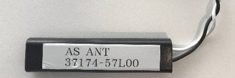
KBRK63T0
Aug 19, 2020Keyless Start System (LF Transmitter)
Equipment Class
DCD - Part 15 Low Power Transmitter Below 1705 kHz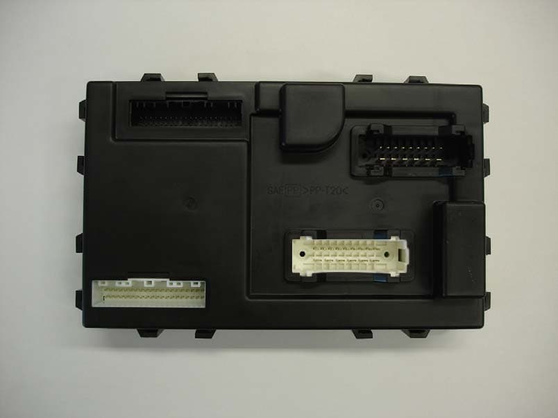
KBRBN009
Jan 19, 2010Automotive Entry System
Equipment Class
DCD - Part 15 Low Power Transmitter Below 1705 kHz
KBRTS003
Jan 20, 2005Vehicle Door Lock Transceiver
Equipment Class
DSR - Part 15 Remote Control/Security Device Transceiver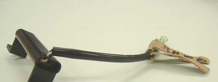
KBRS64J3
Jan 20, 2005Vehicle Door Lock Transceiver
Equipment Class
DCD - Part 15 Low Power Transmitter Below 1705 kHz