KBRK63T0Keyless Start System (LF Transmitter)
Marelli Corporation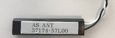
Click to zoom
Application Details
- Equipment Class
- DCD - Part 15 Low Power Transmitter Below 1705 kHz
- Date of Grant
- Aug 19, 2020
- Application Purpose
- Original Equipment
- Date of Application
- Aug 19, 2020
- Equipment Note
- Keyless Start System (LF Transmitter)
- Frequency Range
- 0.12500000 - 0.12500000
- Company
- Marelli Corporation
- Country
- Japan
Documents & Files
Document Text
Text extracted from the exhibit documents filed with the FCC. Open a document above to read the original.
Users Manual
USER OPERATION INSTRUCTION KEYLESS START SYSTEM This system uses coded radio signalsto communicate with the vehicleand remote controller when the remote controlleris near the vehicle such as in your pocket or purse. It allows the vehicle’s door lock/unlock, and startthe enginewithout inserting the ignition Key. It ispossible to use the control entry function. △CAUTION ●Be sure to carry the remote controller. ●Don’tleave the vehicle when the remote controller is in it. ●This systemmay not perform correctly dependon the environment or operation conditions, if you do not use it correctly. ・The remote controller transmitsthe faint radio waves. ・Whenthere are strong signals coming fromthetelevision tower, the power station orthe cellularphone. ・When the remote controlleris in contact witha metallicmaterial or covered by it. ・Whenanotherradio wave-type remote controlleris used nearby. ・When the remote controlleris placed near an electric appliance such as a personal computer. ●The remote controllercontinually consumes battery power when itreceives a signal to communicate with the vehicles. ●Batterylife is about 2 years, although it varies depending onoperationconditions. Pleasereplace the new one if the battery runs down or power is low. ●Battery life may quickly run down if the remote controller received strong signal long time. Don’t place the remote controllernear an electricappliance such as a televisionor personal computer. 1.KEYLESS START SYSTEMOPERATION You can lock or unlock the doors without taking the remote controllerout from your pocket or purse when you carry the remote controller. You can lock or unlock all doorsby pushing the door handle request switch or the back door handle request switch within the realm of operation. 2. Locking doors 1.Stop the engine and get out of your vehicle with yourremote controller. 2.Close all the doors. 3.Push thedoorhandle request switchor the back door handle request switch. 4.Alldoorswill lock. 3.Unlocking doors 1.Push the door handle request switch. ・The driver door unlock Front passenger side or back door. ・Only corresponding door unlocks. 4.OPERATING THE ENGINE ・LOCK(Normal parking position) This position activates only lock/unlock the door functions. ・ACC(Accessories) This position activates electrical accessories such as the radio, when the engine is not running. ・ON(Normal operating position) This position turns on the ignition system and electricalaccessories. ・START This position is startsthe engine. Starting the engine When driving the vehicle, be sure to carry theremote controller. 1. The shift knob locatedin the Parking position. 2. Securely depress the brake pedal. 3.Securely push the push engine start switch and the engine will be started. △WARNING Do not start the engine from outside the vehicle through the window. Doing so could lead an accident and injury. Be sure to sit in the driver seat to use the remote controller. For important safety information, see “Starting the engine “in the Starting and driving section. ●The warning indicated in the instrument panel (meter) ifthe push engine start switchis pushed under the following condition. It is not possible to start the enginewhen. ・You don’t have the remote controller. ・The remote controller battery has run down. ・You have a remote controllerfor another vehicle. ・The engine may not start if the remote controlleris placedin below. a) In the glove box b)In the door pocket c) On the instrument panel d)Corner of interiorcompartment Stopping the engine Removethe shift knob to the Parkingposition. Push the push engine start switch and the engine will be stopped. KEYLESS START SYSTEMOPERATING RANGE ・The keyless start function can be operated inside or outside the vehiclewhen you carry the remote controller. ・The operating range of keyless start system may narrow if the remote controller battery is run down or the remote controller received strong wave and noise. Operating range of the door lock/unlock function. The outside sensors are in the front door handlesand the back door handle. The operating range of the door lock/unlock functions areshown in the illustrations. Front door: 60cm from thefront door handles andBack doorhandle. ・The remote controller may not operate if you are too close to the door glass. ・Anyone whopossibleto open the door lock / unlockwithout remote controllerif it is in the operating range. Operating range for engine start function The operating range for starting the engine is inside the vehicle. ●The engine may not start if the remote controlleris below location. ・On theinstrument panel. ・Inside the glovebox. ・In door pocket. ・Corner of interior compartment. ●The engine may start if the remote controlleris near the door or door glass outside the vehicle . OPERATION WITH REMOTE KEYLESS ENTRY SYSTEM It is possible to lock/unlock all doors andactivate the panic alarm. The LOCK/UNLOCK button on the remote controllercan operate at a distance of approximately 10m from the vehicle.(The effective distance depends upon the condition around the vehicle) The BACK DOOR button on the remote controllercan operate at a distance of approximately 10m from the vehicle. Using the panic alarm You may activate the alarm to call attentionas followsifyou feel threatenednear your vehicle. 1.Push the PANIC button on the remote controllerfor longer 0.5 seconds. 2.The theft warning alarm and the headlights will activatestay on for 30 seconds. 3.The panic alarm stops when it satisfied below situation. ・Runningfor 30 seconds. ・Pressed the LOCK or the UNLOCK button. ・Pressed the panic button for longer than 0.5 seconds. BATTERY REPLACEMENT Replace the battery as below. 1.Insert a flat-blade screwdriver wrapped with a cloth into the slit of the top and twist it to separate the upper part from the lower part. 2.Replace the battery with a new one. ・Don’t touch the internal circuit and electric terminals as it could cause a malfunction. Recommended battery:CR2032 Make sure that the -side faces th…
Text truncated - open the document above for the full version.
External Photos
K63T0 External Photo LF Antenna EXternal Photo Room Center/Bk Room Rear Dr /As
ID Label/Location Info
Label Position Label MODEL No:K63T0 Identification code 57mm 33mm Bar code * X X X X X X X X * E 11 116RI-XXXXXX CCAB06LPXXX0TY 10R-05 XXXXX BCM ID :XXXXX LOT No :XXXX PART No :37171-XXXXX FCC ID :KBRK63T0 CONATEL PY :XXXX-XX-X-XXXXXX TYPE FOR EMC : XXXXX TYPE FOR IMMOBI : XXXXX MARELLI Corp. MADE IN THAILAND Label (30.5) (41.5) CNC ID:XX-99999
Internal Photos
K63T0 Internal Photo Room Center/Bk(Back Door) Room Rear Dr(Driver Door) /As(Assistant Door)
Test Report
Test report No. : 13392309H Page : 1 of 30 Issued date : July 20, 2020 FCC ID : KBRK63T0 UL Japan, Inc. Ise EMC Lab. 4383-326 Asama-cho, Ise-shi, Mie-ken 516-0021 JAPAN Telephone : +81 596 24 8999 Facsimile : +81 596 24 8124 Report Cover Page - 13-EM-F0429 Issue # 17.0 CERTIFICATE 5107.02 RADIO TEST REPORT Test Report No. : 13392309H Applicant : Marelli Corporation Type of EUT : Keyless Start System (LF Transmitter) Model Number of EUT : K63T0 FCC ID : KBRK63T0 Test regulation : FCC Part 15 Subpart C: 2020 Test Result : Complied (Refer to SECTION 3.2) 1. This test report shall not be reproduced in full or partial, without the written approval of UL Japan, Inc. 2. The results in this report appl y only to the sample tested. 3. This sample tested is in compliance with the limits of the above re gulation. 4. The tes t results in this test report are traceable to the national or international standards. 5. This test report must not be used by the customer to claim product certification, approval, or endorsement by the A2LA acc reditation body. 6. This test report covers Radio technical requirements. It does not cover administrative issues such as Manual or non- Radio test related Requirements. (if applicable) 7. The all test items in this test report are conducted b y UL Japan, Inc. Ise EMC Lab. 8. The opinions and the interpretations to the result of the description in this report are outside scopes where UL Japan has been accredited. 9. The information provided from the customer for this report is identified in Section 1. Date of test: July 2 to 10, 2020 Representative test engineer: Akihiko Maeda Engineer Consumer Technology Division Approved by: Shinichi Miyazono Engineer Consumer Technology Division The testing in which "Non-accreditation" is displayed is outside the accreditation scopes in UL Japan. There is no testing item of "Non-accreditation". Test report No. : 13392309H Page : 2 of 30 Issued date : July 20, 2020 FCC ID : KBRK63T0 UL Japan, Inc. Ise EMC Lab. 4383-326 Asama-cho, Ise-shi, Mie-ken 516-0021 JAPAN Telephone : +81 596 24 8999 Facsimile : +81 596 24 8124 REVISION HISTORY Original Test Report No.: 13392309H Revision Test report No. Date Page revised Contents - (Ori ginal) 13392309H July 20, 2020 - - Test report No. : 13392309H Page : 3 of 30 Issued date : July 20, 2020 FCC ID : KBRK63T0 UL Japan, Inc. Ise EMC Lab. 4383-326 Asama-cho, Ise-shi, Mie-ken 516-0021 JAPAN Telephone : +81 596 24 8999 Facsimile : +81 596 24 8124 Reference: Abbreviations (Including words undescribed in this report) A2LA The American Association for Laboratory Accreditation MCS Modulation and Coding Scheme AC Alternating Current MRA Mutual Recognition Arrangement AFH Adaptive Frequency Hopping N/A Not Applicable AM Amplitude Modulation NIST National Institute of Standards and Technology Amp, AMP Amplifier NS No signal detect. ANSI American National Standards Institute NSA Normalized Site Attenuation Ant, ANT Antenna NVLAP National Voluntary Laboratory Accreditation Program AP Access Point OBW Occupied Band Width ASK Amplitude Shift Keying OFDM Orthogonal Frequency Division Multiplexing Atten., ATT Attenuator P/M Power meter AV Average PCB Printed Circuit Board BPSK Binary Phase-Shift Keying PER Packet Error Rate BR Bluetooth Basic Rate PHY Physical Layer BT Bluetooth PK Peak BT LE Bluetooth Low Energy PN Pseudo random Noise BW BandWidth PRBS Pseudo-Random Bit Sequence Cal Int Calibration Interval PSD Power Spectral Density CCK Complementary Code Keying QAM Quadrature Amplitude Modulation Ch., CH Channel QP Quasi-Peak CISPR Comite International Special des Perturbations Radioelectriques QPSK Quadri-Phase Shift Keying CW Continuous Wave RBW Resolution Band Width DBPSK Differential BPSK RDS Radio Data System DC Direct Current RE Radio Equipment D-factor Distance factor RF Radio Frequency DFS Dynamic Frequency Selection RMS Root Mean Square DQPSK Differential QPSK RSS Radio Standards Specifications DSSS Direct Sequence Spread Spectrum Rx Receiving EDR Enhanced Data Rate SA, S/A Spectrum Analyzer EIRP, e.i.r.p. Equivalent Isotropically Radiated Power SG Signal Generator EMC ElectroMagnetic Compatibility SVSWR Site-Voltage Standing Wave Ratio EMI ElectroMagnetic Interference TR Test Receiver EN European Norm Tx Transmitting ERP, e.r.p. Effective Radiated Power VBW Video BandWidth EU European Union Vert. Vertical EUT Equipment Under Test WLAN Wireless LAN Fac. Factor FCC Federal Communications Commission FHSS Frequency Hopping Spread Spectrum FM Frequency Modulation Freq. Frequency FSK Frequency Shift Keying GFSK Gaussian Frequency-Shift Keying GNSS Global Navigation Satellite System GPS Global Positioning System Hori. Horizontal ICES Interference-Causing Equipment Standard IEC International Electrotechnical Commission IEEE Institute of Electrical and Electronics Engineers IF Intermediate Frequency ILAC International Laboratory Accreditation Conference ISED Innovation, Science and Economic Development Canada ISO International Organization for Standardization JAB Japan Accreditation Board LAN Local Area Network LIMS Laboratory Information Management System Test report No. : 13392309H Page : 4 of 30 Issued date : July 20, 2020 FCC ID : KBRK63T0 UL Japan, Inc. Ise EMC Lab. 4383-326 Asama-cho, Ise-shi, Mie-ken 516-0021 JAPAN Telephone : +81 596 24 8999 Facsimile : +81 596 24 8124 CONTENTS PAGE SECTION 1: Customer information ..................................................................................................... 5 SECTION 2: Equipment under test (EUT) ........................................................................................... 5 SECTION 3: Test specification, procedures & results ........................................................................ 6 SECTION 4: Operation of EUT during testing .................................................................................... 9 SECTION 5: Radiated emission (Fundamental and Spurious Emission) .......................................…
Text truncated - open the document above for the full version.
Test Setup Photos
Test report No. : 13392309H Page : 28 of 30 Issued date : July 20, 2020 FCC ID : KBRK63T0 UL Japan, Inc. Ise EMC Lab. 4383-326 Asama-cho, Ise-shi, Mie-ken 516-0021 JAPAN Telephone : +81 596 24 8999 Facsimile : +81 596 24 8124 APPENDIX 3: Photographs of test setup Radiated Emission Photo 1 Photo 2 Test report No. : 13392309H Page : 29 of 30 Issued date : July 20, 2020 FCC ID : KBRK63T0 UL Japan, Inc. Ise EMC Lab. 4383-326 Asama-cho, Ise-shi, Mie-ken 516-0021 JAPAN Telephone : +81 596 24 8999 Facsimile : +81 596 24 8124 Worst Case Position ECU Below 30 MHz X-axis Above 30 MHz X-axis X-axis Y-axis Z-axis Test report No. : 13392309H Page : 30 of 30 Issued date : July 20, 2020 FCC ID : KBRK63T0 UL Japan, Inc. Ise EMC Lab. 4383-326 Asama-cho, Ise-shi, Mie-ken 516-0021 JAPAN Telephone : +81 596 24 8999 Facsimile : +81 596 24 8124 Worst Case Position Dr ANT Below 30 MHz Z-axis Above 30 MHz X-axis Bk ANT Below 30 MHz Z-axis Above 30 MHz X-axis X-axis X-axis Y-axis Y-axis Z-axis Z-axis End of Report
Contact Information
Applicant
Takaichiro Ishida
Technical Contact
UL Japan, Inc.Shinichi Miyazono
[email protected]81-596-24-8999
4383-326 Asama-cho, Ise-shi · Mie-ken · Japan
Test Firm
UL Japan, Inc.(Ise)Takayuki Shimada
Technical Specifications
| # | Rule Parts | Frequency Range | Power Output |
|---|---|---|---|
| 1 | 15C | 0.125 MHz - 0.125 MHz | - |
Other Applications from Marelli Corporation
KBRR55T0
Jun 30, 2021SW ASSY-SMART KEYLESS
Equipment Class
DSC - Part 15 Security/Remote Control Transmitter
KBRBN009
Jan 19, 2010Automotive Entry System
Equipment Class
DCD - Part 15 Low Power Transmitter Below 1705 kHz
KBRTS003
Jan 20, 2005Vehicle Door Lock Transceiver
Equipment Class
DSR - Part 15 Remote Control/Security Device Transceiver
KBRS64J3
Jan 20, 2005Vehicle Door Lock Transceiver
Equipment Class
DCD - Part 15 Low Power Transmitter Below 1705 kHz
KBRTS004
Nov 04, 2004Vehicle Remote Control Transmitter
Equipment Class
DSC - Part 15 Security/Remote Control Transmitter