KBRTS003Vehicle Door Lock Transceiver
Marelli Corporation
Click to zoom
Application Details
- Equipment Class
- DSR - Part 15 Remote Control/Security Device Transceiver
- Date of Grant
- Jan 20, 2005
- Application Purpose
- Original Equipment
- Date of Application
- Jan 20, 2005
- Equipment Note
- Vehicle Door Lock Transceiver
- Frequency Range
- 315.00000000 - 315.00000000
- Company
- Marelli Corporation
- Country
- Japan
Documents & Files
Document Text
Text extracted from the exhibit documents filed with the FCC. Open a document above to read the original.
Users Manual
USER OPERATION INSTRUCTION (DRAFT) KEY FREE SYSTEM The key free uses coded radio signals to communicate with the vehicle. When the key free is near the vehicle such as in your pocket or purse. It allows the vehicle to be locked unlocked, or started without inserting the ignition Key. It is also possible to use the control entry function. △ CAUTION ・ Be sure to carry the key free with you. ・ Do not leave the vehicle with the key free inside. ・ The key free may not function correctly depending on the environment or operating conditions, if you do not use it correctly. ・The key free transmits faint radio waves. ・ When there are strong signals coming from a television tower, power station or a cellular phone with you. ・ When the key free is in contact with or covered by a metallic material. ・ When radio wave-type remote control entry is used nearby. ・ When the key free is placed near an electric appliance such as a personal Computer. ・ The key free continually consumes battery power as the key receives a signal to communicate with the vehicles. ・ Battery life is about 2 years, although it varies depending on the operating conditions. When the battery of the key free is low, If the battery runs down, replace it with a new one. ・ If the key free receive strong signal over an extended period of time the Battery could quickly run down. Do not place the key free near an electric appliance such as a television set or personal computer. 1. KEY FREE OPERATION You can lock or unlock the doors without taking the key out from your pocket or purse. When you carry the key free with you. You can lock or unlock all door by pushing the door handle request switch or back door handle request switch within the range of operation. 2. Locking doors 1. Turn the ignition knob to the LOCK position and remove the ignition key if any metal key is in the ignition knob. 2. Close all the doors. 3. Push any front door or the back door handle request switch while carrying the key free with you 4. All the door and back door will lock. 3.Unlocking doors 1. Push the door handle request switch once Drivers side: ・ The driver door unlock Front passenger side or back door. ・ Only corresponding door unlocks. 4.OPERATING THE ENGINE Ignition knob positions Push in the ignition knob in the range when you turn it. LOCK(Normal parking position) The ignition knob can only be locked in the position. The ignition knob will be unlocked when it is pushed in , and turned to the ACC position while carrying the key free . ACC(Accessories) This position activates electrical accessories such as the radio, when the engine is not running. ON(Normal operating position) This position turns on the ignition system and electrical accessories. START This position starts the engine. As soon as the engine has started, release the knob immediately. It will automatically return to the ON position. Starting the engine When driving the vehicle, be sure to carry the intelligent key with you. 1 Securely depress the brake pedal. 2.Slowly push the ignition knob in/ When the intelligent key warning light in the instrument (meter) panel comes on in blue, the ignition knob can be turned. 3.Turn the ignition knob to START and the engine will be started. 2. When the engine starts, release the ignition knob. △ WA R N I N G Do not start the engine from outside the vehicle through the window. Doing so could lead an accident and injury. Be sure to sit in the drivers seat to use the key. For important safety information, see “Starting the engine “ in the Starting and driving section. ・ When the ignition knob is pushed under the following condition, the key warning light in the instrument (meter) panel comes on in red. It is not possible to turn the ignition knob when. ・ you do not have the intelligent key with you ・The intelligent key battery has run down ・You have a key free for another vehicle with you. ・ Slowly turn the ignition knob after the key warning light comes on in blue. if it is turned quickly , it may stick and be difficult in turn. ・ The engine may not start if the intelligent key is placed. ・inside the glove box or the door pocket ・ on the instrument panel ・ in the corner of interior compartment ・ if it is difficult to turn the ignition knob perform the following. ・Push the ignition knob again and slowly turn it . ・ Turn the ignition knob while gently turning the steering wheel to the left or right Stopping the engine Shift the selector lever to the P position. Turn the ignition knob to ACC. KEY FREE OPERATING RANGE The key free function can be used only when you carry the key with you and operate as specified in the operating range inside or outside the vehicle. When the key free battery runs down or where there are strong radio waves or noise , the operating range may be narrower or the key may be inoperative. Operating range of the door lock/unlock function The outside sensors are in the front door handle and the back door handle. The operating range of the door lock/unlock function is with in 60cm from the door handle of Front door and Back door. ・ If you are too close to the door glass , the intelligent key may not operate. ・ If the key free is in the operating range, it is possible for anyone who dose not carry the key free to lock/unlock the does by pushing the door handle request switch. Operating range for engine start function The operating range for starting the engine is inside the vehicle. ・ If the key free is on the instrument panel , inside the glove box or door pocket ., or the corner of interior compartment , it may not be possible to start the engine. ・ If the key free is near the door or door glass outside the vehicle it may be possible to start the engine. OPERATION WITH KEY FREE REMOTE KEYLESS ENTRY SYSTEM It is possible to lock/unlock all doors. activate the panic alarm Before locking the doors, make sure the key is not left in the vehicle. The LOCK/UNLOCK button on the intelligent key can operate at a distance of approximately 10m fr…
Text truncated - open the document above for the full version.
Cover Letter(s)
Tochigi-ken Tochigi-ken
Cover Letter(s)
Tochigi-ken
Cover Letter(s)
Tochigi-ken
External Photos
Calsonic Kansei Corp. Transmitter of Keyless Entry System FCC ID: KBRTS003 External photos Front view Rear view
Internal Photos
Calsonic Kansei Corp. Transmitter of Keyless Entry System FCC ID: KBRTS003 Internal photos Inside view Calsonic Kansei Corp. Transmitter of Keyless Entry System FCC ID: KBRTS003 Circuit Board <Front> Circuit Board <Rear > Calsonic Kansei Corp. Transmitter of Keyless Entry System FCC ID: KBRTS003 Coil Antenna
Test Report
Test report No. : 25BE0108-HO-1 Page : 2 of 19 Issued date : January 7, 2005 FCC ID : KBRTS003 Revised date : January 14, 2005 UL Apex Co., Ltd. Head Office EMC Lab. 4383-326 Asama-cho, Ise-shi, Mie-ken 516-0021 JAPAN Telephone : +81 596 24 8116 Facsimile : +81 596 24 8124 MF060b(10.04.03) CONTENTS PAGE SECTION 1: Client information .................................................................................................................... 3 SECTION 2: Equipment under test (E.U.T.)................................................................................................ 3 SECTION 3: Test specification, procedures & results ................................................................................ 4 SECTION 4: Operation of E.U.T. during testing ......................................................................................... 6 SECTION 5: Spurious Emission .................................................................................................................... 8 SECTION 6: Automatically deactivate ......................................................................................................... 9 SECTION 7: -20dB Bandwidth...................................................................................................................... 9 APPENDIX 1: Photographs of test setup .................................................................................................... 10 Spurious Emission (Transmitting)(Radiated) ......................................................................................................10 Spurious Emission (Receiving) (Radiated)........................................................................................................... 11 Worst Case Position (Transmitting) (X-axis:Horizontal / Y-axis:Vertical) .......................................................12 APPENDIX 2:Test instruments .................................................................................................................... 13 APPENDIX 3: Data of EMI test.................................................................................................................... 14 Radiated Spurious Emission (Transmitting)........................................................................................................14 Radiated Spurious Emission (Receiving) .............................................................................................................17 99% Occupied Bandwidth and -20dB Bandwidth ..............................................................................................18 Automatically deactivate .......................................................................................................................................19 Test report No. : 25BE0108-HO-1 Page : 3 of 19 Issued date : January 7, 2005 FCC ID : KBRTS003 Revised date : January 14, 2005 UL Apex Co., Ltd. Head Office EMC Lab. 4383-326 Asama-cho, Ise-shi, Mie-ken 516-0021 JAPAN Telephone : +81 596 24 8116 Facsimile : +81 596 24 8124 MF060b(10.04.03) SECTION 1: Client information Company Name : Calsonic Kansei Corp. Address : 8 Sakae-cho Sano-shi Tochigi, 327-0816 Japan Telephone Number : +81-283-21-8409 Facsimile Number : +81-283-21-8547 Contact Person : Kenichiro Kobayashi SECTION 2: Equipment under test (E.U.T.) 2.1 Identification of E.U.T. Type of Equipment : Hand Unit of Smart Keyless Entry System Model No. : TS003 Sample No. : 5 Country of Manufacture : Japan Rating : DC3V Receipt Date of Sample : October 4, 2004 Condition of EUT : Production prototype (Not for Sale: This sample is equivalent to mass-produced items.) 2.2 Product Description Clock frequency CPU: 2.2MHz Equipment Type Transmitter Frequency of Operation 315MHz Type of Modulation FSK Antenna Type Pattern Antenna Mode of Operation Simplex ITU code F1D Method of freqeuncy generation Resonator Operating voltage (Inner) DC 3V Operating freqeuncy range -10 to +60deg.C. Equipment Type Receiver Frequency of Operation 125kHz Operating voltage (Inner) DC 3V FCC 15.31 (e) This test was performed with the New Battery (DC 3.0V) and the constant voltage was supplied to this EUT during the tests. Therefore, this EUT complies with the requirement. FCC Part 15.203 Antenna requirement It is impossible for end users to replace the antenna, because the antenna is mounted inside of the EUT. Therefore, the equipment complies with the antenna requirement of Section 15.203. FCC Part 15.111(b) The receiving antenna is installed on the EUT, which is unremovable. Therefore, this EUT complies with the requirement in Section FCC Part 15.111(b). Test report No. : 25BE0108-HO-1 Page : 4 of 19 Issued date : January 7, 2005 FCC ID : KBRTS003 Revised date : January 14, 2005 UL Apex Co., Ltd. Head Office EMC Lab. 4383-326 Asama-cho, Ise-shi, Mie-ken 516-0021 JAPAN Telephone : +81 596 24 8116 Facsimile : +81 596 24 8124 MF060b(10.04.03) SECTION 3: Test specification, procedures & results 3.1 Test Specification Test Specification : FCC Part 15 Subpart C 2004 Title : FCC 47CFR Part15 Radio Frequency Device Subpart C Intentional Radiators Section 15.231 Periodic operation in the band 40.66 - 40.70MHz and above 70MHz Test Specification : FCC Part 15 Subpart B : 2004 Title : FCC 47CFR Part15 Radio Frequency Device Subpart B Unintentional Radiators Section 15.109 Radiated emission limits 3.2 Procedures and results 1) FCC Part 15 Subpart C: 2004 No. Item Test Procedure Specification Remarks Worst margin*0) Result 1 Automatically deactivate ANSI C63.4:2003 13. Measurement of intentional radiators FCC Section 15.231(a)(1) Radiated N/A Complied 2 Electric Field Strength of Fundamental Emission ANSI C63.4:2003 13. Measurement of intentional radiators FCC Section 15.231(b) Radiated 2.7dB QP 315MHz Horizontal Complied 3 Electric Field Strength of Spurious Emission ANSI C63.4:2003 13. Measurement of intentional radiators FCC Section 15.205 FCC Section 15.209 FCC Section 15.231(b) Radiated 5.2dB QP 630.125MH…
Text truncated - open the document above for the full version.
Test Setup Photos
Test report No. : 25BE0108-HO-1 Page : 10 of 19 Issued date : January 7, 2005 FCC ID : KBRTS003 Revised date : January 14, 2005 UL Apex Co., Ltd. Head Office EMC Lab. 4383-326 Asama-cho, Ise-shi, Mie-ken 516-0021 JAPAN Telephone : +81 596 24 8116 Facsimile : +81 596 24 8124 MF060b(10.04.03) APPENDIX 1: Photographs of test setup Spurious Emission (Transmitting)(Radiated) Front Rear Test report No. : 25BE0108-HO-1 Page : 11 of 19 Issued date : January 7, 2005 FCC ID : KBRTS003 Revised date : January 14, 2005 UL Apex Co., Ltd. Head Office EMC Lab. 4383-326 Asama-cho, Ise-shi, Mie-ken 516-0021 JAPAN Telephone : +81 596 24 8116 Facsimile : +81 596 24 8124 MF060b(10.04.03) Spurious Emission (Receiving) (Radiated) Front Rear Test report No. : 25BE0108-HO-1 Page : 12 of 19 Issued date : January 7, 2005 FCC ID : KBRTS003 Revised date : January 14, 2005 UL Apex Co., Ltd. Head Office EMC Lab. 4383-326 Asama-cho, Ise-shi, Mie-ken 516-0021 JAPAN Telephone : +81 596 24 8116 Facsimile : +81 596 24 8124 MF060b(10.04.03) Worst Case Position (Transmitting) (X-axis:Horizontal / Y-axis:Vertical) X-axis Y-axis Z-axis
Contact Information
Applicant
Takaichiro Ishida
Technical Contact
Non-Technical Contact
UL Apex Co., Ltd.Kanako Sanda
[email protected]81-596-24-8116
Test Firm
UL Apex Co., Ltd.Tetsuya Hashimoto
Technical Specifications
| # | Rule Parts | Frequency Range | Power Output |
|---|---|---|---|
| 1 | 15.231 | 315 MHz - 315 MHz | - |
Other Applications from Marelli Corporation

KBRR55T0
Jun 30, 2021SW ASSY-SMART KEYLESS
Equipment Class
DSC - Part 15 Security/Remote Control Transmitter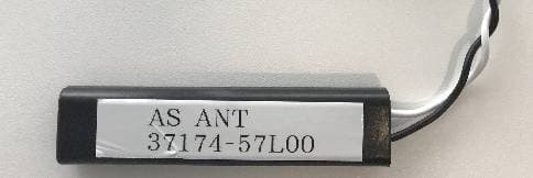
KBRK63T0
Aug 19, 2020Keyless Start System (LF Transmitter)
Equipment Class
DCD - Part 15 Low Power Transmitter Below 1705 kHz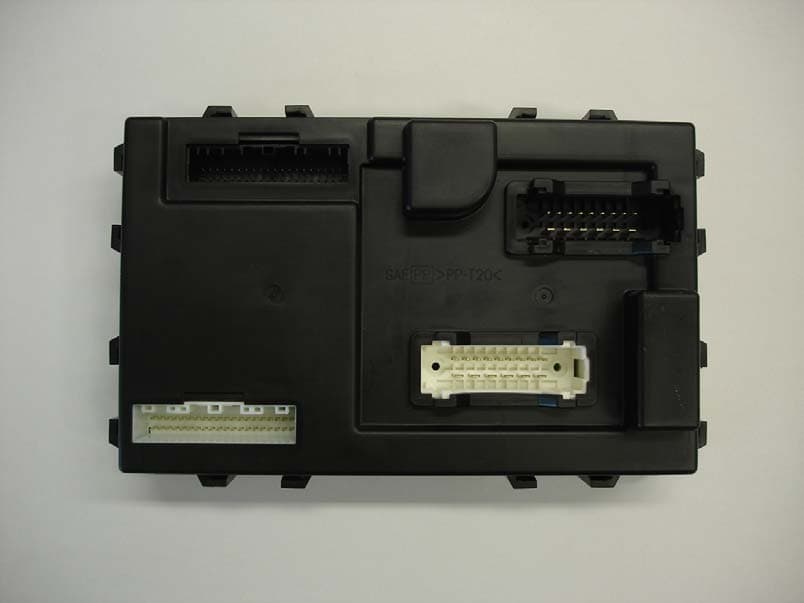
KBRBN009
Jan 19, 2010Automotive Entry System
Equipment Class
DCD - Part 15 Low Power Transmitter Below 1705 kHz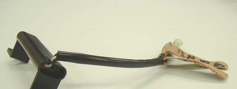
KBRS64J3
Jan 20, 2005Vehicle Door Lock Transceiver
Equipment Class
DCD - Part 15 Low Power Transmitter Below 1705 kHz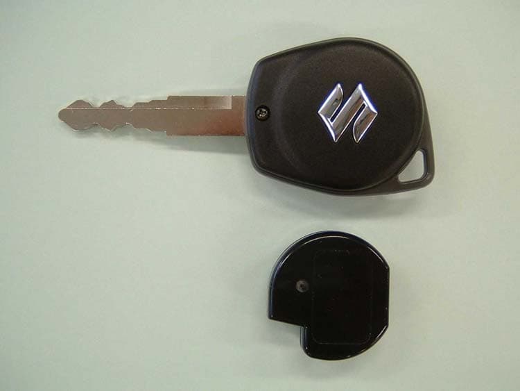
KBRTS004
Nov 04, 2004Vehicle Remote Control Transmitter
Equipment Class
DSC - Part 15 Security/Remote Control Transmitter