KBRBSVU17Vechicle Security Immobilizer System
Marelli Corporation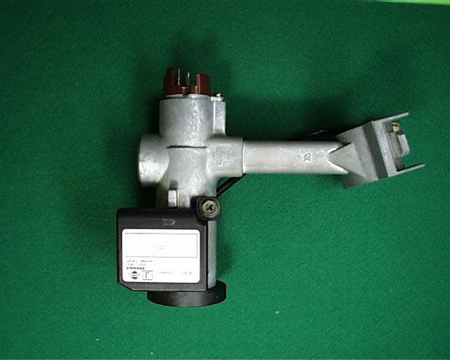
Click to zoom
Application Details
- Equipment Class
- DCD - Part 15 Low Power Transmitter Below 1705 kHz
- Date of Grant
- Oct 11, 2001
- Application Purpose
- Original Equipment
- Date of Application
- Oct 11, 2001
- Equipment Note
- Vechicle Security Immobilizer System
- Frequency Range
- 0.12500000 - 0.12500000
- Company
- Marelli Corporation
- Country
- Japan
Documents & Files
Document Text
Text extracted from the exhibit documents filed with the FCC. Open a document above to read the original.
Users Manual
FCC ID: KBRBSVU17 FCC ID: KBRBSVU17
External Photos
External photo FCC ID: KBRBSVU17 FCC ID: KBRBSVU17
Internal Photos
Internal photo FCC ID: KBRBSVU17
Operational Description
FCC ID : KBRBSVU17 - - 1. GENERAL TECNIAL DESCRIPTIN 1-1 INTENDED USE AND OPREATION INSTRUCTIONS This equipment, known as an immobilizer, is a vehicle anti-theft device to prevent from the unauthorized use of a motor vehicle. The equipment allows the ignition system to be disabled when the ignition system is manipulated without using the proper key, such as by direct connection of power supplying lines or breakdown of the key-cylinder. The system is a radio frequency apparatus comprising of a transponder integrally incorporated within the ignition key, a radio frequency module (RFM) with an antenna installed on the key-cylinder case and a controller (BCM) controlling the operation of the RF module. Whenever the ignition key is inserted the key-cylinder and turned to the “ON” position, the RFM continues to generate a radio frequency carrier operating on frequency 125kHz powered by the BCM, and bi-directional transmission in half duplex mode between the BCM and the transponder occurs. The transponder requires no internal power supply; it derives its power from the magnetic component of the radio frequency carrier. Data is stored in the transponder and the BCM in its non-volatile memory (EEPROM). Data is transmitted via radio frequency link by ASK-modulating this carrier. Absorption modulation is used to transmit data from the transponder to the BCM. The transponder absorbs the magnetic field which hence modulates the current in the antenna of the RFM. Upon receiving the start command from the BCM, the energized transponder transmits its identifier to the BCM. The BCM sends its own password (A) together with a set of random numbers to the transponder in return. If the received password matches the password (A) stored in the transponder, the transponder reprogrammed the data using its own password (B) and the set of random numbers received in accordance with the pre-determined protocol, data with the pre-calculated data using the transponder’s password (B) stored in the BCM and same random numbers in turn, whereupon the matching being verified as s result of the comparison. After the comparison the BCM sends the result of the comparison to engine control module (ECM). When coincidence has been verified, the ECM enable the engine to activated, but when the result is negative it will be not allow the engine to be activated. Whenever the ignition switch is turned from the ON position to the OFF position during processing, the system is shifted to ignition OFF mode. The BCM causes the indication lamp on the dashboard to flash when the ignition switch is in the OFF position or a malfunction of the system occurs. The ECM sends a rolling code to the BCM every time the ignition switch is turned from the OFF position to the ON position in order to watch for an unauthorized replacement or a manipulation of the controller. 1-2 SYSTEM CONSTRUCTIONS The construction of system is shown following: Key with a built-in transponder RF module within antenna To Engine Control Module Controller (BCM) FCC ID : KBRBSVU17 - - 1-3 TIMING DIAGRAM The timing diagram of system is shown following: IGN ON OFF IMMOBILIZER SOURCE VOLTAGE 5V 0V IMMOBILIZER SIGNAL (CONT to RF) MAGNETIC FIELD TO TP TRANSMITION OF TP SIGNAL STARTING OF ENGIN WITH OK KEYSTARTING OF ENGIN WITH NG KEY DATA OUTPUT TO TP MGNETIC FIELD GENERATED DATA OUTPUT TO TP (MGNETIC FIELD: ASK) TP SIGNAL IS TRANSMITTED (MGNETIC FIELD: AM) TP SIGNAL IS RECEIVED AND KEIY ID IS OUTPUT T1=MAX. 28ms T2=MAX. 1.5ms T3=MAX. 16ms T4=TYP. 9.5ms T5=MIN. 9ms T6=TYP. 9.5ms T7=MAX. 1ms T8=TYP. 5ms T9=MAX. 18ms IMMOBILIZER SIGNAL (RF to CONT) T1T2T3 T4 T1T2T3 T6T5 T7 T4 T6T5 T4 T6T5 T7 T4 T6T5 T4 T6T5 T7 T4 T6T5 T4 T6T5 T7 T4 T6T5 T9T2T3T9T2T3 T8T8 1-4 APPLIED REGLATIONS This equipment will be applied under FCC Rules and Regulations Part 15. FCC ID : KBRBSVU17 - - 2. TECHNICAL SPECIFICATION 2-1 Fundamental Specifications Nominal voltage : 5V (Transformed from the 12V battery) Power source : Regulated lead-acid battery (12V) 2-2 Transponder specifications (Referred to PHILIPS reference manual) Model number : PCF7936AS (Security transponder for car immobileozer manufactured by PHILIPS) Operating frequency : N.A. Number of channel : N.A. Emission designator : N.A. Maximum output field strength : N.A. Type of antenna : Ferrite core antenna 2-3 RF module specifications Operating frequency : 125KHz Frequency tolerance : 0.3% Number of channel : 1 Emission designator : Maximum output field strength : 0.2704W Type of antenna : Loop antenna
Test Report
Test report No.: 22AE0081-YW-1 Page: 2 of 16 Issued date: October 3, 2001 FCC ID: KBRBSVU17 A-pex International Co., Ltd. YOKOWA LAB. 108 Yokowa-cho, Ise-shi, Mie-ken 516-1106 JAPAN Telephone:int +81 596 39 1485 Facsimile: int +81 596 39 0232 CONTENTS PAGE SECTION 1: Client information 3 SECTION 2: Equipment under test (E.U.T.)3 SECTION 3: Test specification, methods & procedures4 SECTION 4: Operation of E.U.T. during testing5 SECTION 5: Summary of test results 7 SECTION 6: Test instruments8 SECTION 7: Radiated emission9 APPENDIX 1: Photographs of test setup11 APPENDIX 2: Data of EMI test13 Test report No.: 22AE0081-YW-1 Page: 3 of 16 Issued date: October 3, 2001 FCC ID: KBRBSVU17 A-pex International Co., Ltd. YOKOWA LAB. 108 Yokowa-cho, Ise-shi, Mie-ken 516-1106 JAPAN Telephone:int +81 596 39 1485 Facsimile: int +81 596 39 0232 SECTION 1: Client information Company name: ClsonicKansei Corp. Trade name: CALSONOC KANSEI Address: 5-24-15 Minamidai, Nakano-Ku, Tokyo, 164-8602 JAPAN Telephone Number: +81-3-5385-0111 Facsimile Number: +81-3-3383-1171 Contact Person: Yasuo Saruki SECTION 2: Equipment under test (E.U.T.) Type of Equipment: Immobilizer System (RF module + Body control module) Model No.: BSVU17 FCC ID: KBRBSVU17 Serial No.: Sample No.1 Condition of EUT: Production prototype Rating: DC 12.0V (Car Battery) Country of Manufacture: Germany and Japan Receipt Date of Sample : August 9, 2001 2.2Product Description Model: BSVU17, referred to as the EUT in this report, is a Immobilizer System (RF module + Body control module). The specification is as follows : Carrier Frequency : 125 kHz Modulation: AM Information antenna: Loop antenna Test report No.: 22AE0081-YW-1 Page: 4 of 16 Issued date: October 3, 2001 FCC ID: KBRBSVU17 A-pex International Co., Ltd. YOKOWA LAB. 108 Yokowa-cho, Ise-shi, Mie-ken 516-1106 JAPAN Telephone:int +81 596 39 1485 Facsimile: int +81 596 39 0232 SECTION 3: Test specification, methods & procedures 3. 1Test Specification Test Specification: FCC Part 15 Subpart C Title: FCC 47CFR Part15 Radio Frequency Device Subpart C Intentional Radiators 15.209 Radiated emission limits; general requirements 3.2Methods & Procedures No.ItemTest ProcedureSpecificationRemarks 1Conducted emissionANSI C63.4:1992 15.207(a) - 2Radiated emissionANSI C63.4:1992 15.209(a) 3m *These tests were performed without any deviations from test procedure except for below exclusions. 3.3 Additions or deviations to standards No.ItemTest ProcedureSpecificationRemarks 1Conducted emissionANSI C63.4:1992 15.207(a) - * This test is not applicable since the EUT does not have AC Port. Test report No.: 22AE0081-YW-1 Page: 5 of 16 Issued date: October 3, 2001 FCC ID: KBRBSVU17 A-pex International Co., Ltd. YOKOWA LAB. 108 Yokowa-cho, Ise-shi, Mie-ken 516-1106 JAPAN Telephone:int +81 596 39 1485 Facsimile: int +81 596 39 0232 SECTION 4: Operation of E.U.T. during testing 4.1Operating Modes The EUT exercise program used during radiated and conducted testing was designed to exercise the various system components in a manner similar to typical use. The operating mode/system were as follows: Operation:Communication mode Justification:The system was configured in typical fashion (as a customer would normally use it) for testing. 4.2 Configuration and peripherals Front View A:EUT B:EUT C : Ferrite Core Top View A:EUT B:EUT C : Ferrite Core *Cabling was taken into consideration and test data was taken under worse case conditions. Test report No.: 22AE0081-YW-1 Page: 6 of 16 Issued date: October 3, 2001 FCC ID: KBRBSVU17 A-pex International Co., Ltd. YOKOWA LAB. 108 Yokowa-cho, Ise-shi, Mie-ken 516-1106 JAPAN Telephone:int +81 596 39 1485 Facsimile: int +81 596 39 0232 Description of EUT and Support equipment No.ItemModel numberSerial numberManufacturerFCC ID ARF moduleBSVU17Sample No.1SIEMENSKBRBSVU17 (EUT) BBody control moduleBSVU17Sample No.1CalsonicKansei Corp.KBRBSVU17 (EUT) CCar Battery50B24L-YUASA- List of cables used No.NameLength (m)ShieldBackshell MaterialRemark I/O Cable1.0N Polyvinyl chloride - DC Power Cable0.3N Polyvinyl chloride - Test report No.: 22AE0081-YW-1 Page: 7 of 16 Issued date: October 3, 2001 FCC ID: KBRBSVU17 A-pex International Co., Ltd. YOKOWA LAB. 108 Yokowa-cho, Ise-shi, Mie-ken 516-1106 JAPAN Telephone:int +81 596 39 1485 Facsimile: int +81 596 39 0232 SECTION 5: Summary of test results 5.1Test results No.ItemTest ProcedureWorst marginResult 1Radiated emissionANSI C63.4:1992 Fundamental 21.6dB (0.1250MHz: 0degrees) Spurious 7.0dB (57.9500MHz: Horizontal) Complied A-PEX INTERNATIONAL hereby confirms that E.U.T., in the configuration tested, complies with the specifications FCC Part15 Subpart C §15.209(a). <–20dB Bandwidth> See Appendix A2 and A3 5.2Uncertainty Radiated Emission Test Measurement distance of 3m: The measurement uncertainty (with a 95% confidence level) for this test using Loop antenna is ±2.5dB. The measurement uncertainty (with a 95% confidence level) for this test using Biconical antenna is ±4.4dB. The measurement uncertainty (with a 95% confidence level) for this test using Logperiodic antenna is ±4.8dB. The data listed in this test report may exceed the test limit because it does not have enough margin. The data listed in this test report has enough margin, more than site margin. 5.3Test equipment used See SECTION 6: Test instruments 5.4Test Location A-PEX International Co.,Ltd. Yokowa No.3 test site 108 Yokowa-cho, Ise-shi, Mie-ken 516-1106 Japan Telephone number: +81-596-39-1485 Facsimile number: +81-596-39-0232 This site has been fully described in a report submitted to FCC office, and listed on September 12, 2000 (Registration number: 90412). *NVLAP Lab. code : 200109-0 5.5Test Configuration Photographs See Appendix 1. 5.6Data of EMI Test See Appendix 2. Test report No.: 22AE0081-YW-1 Page: 8 of 16 Issued date: October 3, 2001 FCC ID: KBRBSVU17 A-pex International Co., Ltd. YOKOWA LAB. 108 Yokowa-cho, Ise-shi, Mie-ken 516-1106 JAPAN Telephone:int +81 596 39 1485 F…
Text truncated - open the document above for the full version.
Test Setup Photos
Test report No.: 22AE0081-YW-1 Page: 12 of 16 Issued date: October 3, 2001 FCC ID: KBRBSVU17 A-pex International Co., Ltd. YOKOWA LAB. 108 Yokowa-cho, Ise-shi, Mie-ken 516-1106 JAPAN Telephone:int +81 596 39 1485 Facsimile: int +81 596 39 0232 Radiated emission
Contact Information
Applicant
Takaichiro Ishida
Technical Contact
A-Pex International Co., Ltd.Naoki Sakamoto
[email protected]+81 596 39 1485
108 Yokowa-Cho · Ise-shi, Mie-ken · Japan
Test Firm
UL Japan, Inc.Kazunori Nishimura
Technical Specifications
| # | Rule Parts | Frequency Range | Power Output |
|---|---|---|---|
| 1 | 15C | 0.125 MHz - 0.125 MHz | - |
Other Applications from Marelli Corporation

KBRR55T0
Jun 30, 2021SW ASSY-SMART KEYLESS
Equipment Class
DSC - Part 15 Security/Remote Control Transmitter
KBRK63T0
Aug 19, 2020Keyless Start System (LF Transmitter)
Equipment Class
DCD - Part 15 Low Power Transmitter Below 1705 kHz
KBRBN009
Jan 19, 2010Automotive Entry System
Equipment Class
DCD - Part 15 Low Power Transmitter Below 1705 kHz
KBRTS003
Jan 20, 2005Vehicle Door Lock Transceiver
Equipment Class
DSR - Part 15 Remote Control/Security Device Transceiver
KBRS64J3
Jan 20, 2005Vehicle Door Lock Transceiver
Equipment Class
DCD - Part 15 Low Power Transmitter Below 1705 kHz