KBRCSSU53Car Immobilizer
Marelli Corporation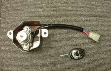
Click to zoom
Application Details
- Equipment Class
- DCD - Part 15 Low Power Transmitter Below 1705 kHz
- Date of Grant
- Nov 09, 2002
- Application Purpose
- Original Equipment
- Date of Application
- Nov 09, 2002
- Equipment Note
- Car Immobilizer
- Frequency Range
- 0.12500000 - 0.12500000
- Company
- Marelli Corporation
- Country
- Japan
Documents & Files
Document Text
Text extracted from the exhibit documents filed with the FCC. Open a document above to read the original.
Users Manual
9.user operation instruction operation instructions for this system are contained in the motor cycle’s user manual,from which the portions related to the system are transcribed below: -This motor cycle is equipped with an immobilizer system. -The immobilizer system is designed to disable the engine unless a registered key dedicated to your motor cycle is used,and it can prevent unauthorized use of the vehicle. -Operation procedure: each key incorporates an unique identification code. When a key is inserted into the ignition switch and turned to the “ON” position,the engine controller installed on the vehicle receives the code from the inserted key and judges whether the inserted key is a registered one or not. The engine can be activated only when the result of the judgement is “OK”. The driver can see the result of the judgement shown in the indicator in the instrument Panel. In the case that the inserted key is a registered one,the indicator light stays on for 2 seconds,whereas for an unregistered key, after the initial 2 seconds the indicator blinks as long as the ignition switch is in the “ON” position. State of ignition switch For a registered key Indicator lighting mode For an unregistered key -notice on handling: The key should not suffer ant strong impact also do not leave it in a high-temerature Environment,since electronic devices are incorporated within the key. If you lose your key,see your HONDA dealer immediately,and bring with you all of the Remaining keys you have,the key number plate supplied with your key and you vehicle. Care should be taken not to lose all of keys,as in such a case the ignition unit will Have to be replaced totally. A duplicated key cannot be used unless the code-registering procedure is performed. ON OFF 2 Sec The engine is activated ON OFF ON OFF A maximum of four keys can be registered. If you want to have additional keys other than those you have been supplied with,follow the same procedure as required when you lose a key. Never make a change nor a modification on the immobilizer system,as it may result in disabling the engine. Changes or modifications not expressly approved of by the manufacturer for compliance could void the user’s authority to operate the device. FCC WARNING Changes or modifications not expressly approved by the party responsible for compliance could void the user’s authority to operate the equipment. NOTICE This device complies with Part 15 of the FCC Rules. Operation is subject to the following two conditions: (1) this device may not cause harmful interference, and (2) this device must accept any interference received, including interference that may cause undesired operation.
External Photos
CalsonicKansei Corp. Immobiliser system<FCC ID: KBRCSSU53> <External Photos> Front view CalsonicKansei Corp. Immobiliser system<FCC ID: KBRCSSU53> Rear view CalsonicKansei Corp. Immobiliser system<FCC ID: KBRCSSU53> CalsonicKansei Corp. Immobiliser system<FCC ID: KBRCSSU53> Overview <front> CalsonicKansei Corp. Immobiliser system<FCC ID: KBRCSSU53> Overview <Rear>
ID Label/Location Info
3.Labelling of equipment The labeling is affixed on the amplifier ca as shown bellow. BRAND NAME : HONDA MANUFACTURER : CalsonicKansei Corp. MODEL NO. : CSSU53 FCC ID : KBRCSSU53 IC : 2111B-CSSU53
Internal Photos
CalsonicKansei Corp. Immobiliser system<FCC ID: KBRCSSU53> <Internal Photos> Circuit board <front view> CalsonicKansei Corp. Immobiliser system<FCC ID: KBRCSSU53> Circuit board <rear view>
Operational Description
1. 1-1. INTENDED USE AND OPERATION INSTRUCTIONS This equipment, known as a car immobilizer, is an anti-theft device to prevent unauthorized use of a motorcycle. The equipment allows the engine to be disabled when the ignition system is manipulated without using the proper key, such as by the direct connection of a power supply line or the breakdown of the key-cylinder. The system is composed of a radio frequency link between a transponder integrally incorporated within an ignition key and a radio frequency module (RFM) with an antenna installed on the key-cylinder case of the ignition system and an engine control module (ECM) connected by wire to the RFM. The ECM controls operation of the engine. Whenever the ignition key is inserted into the key-cylinder and turned to the “ON” position, the RFM continues to generate a radio frequency operating on frequency 125 kHz powered by the ECM, and a bi-directional transmission in half duplex mode between the RCM and the transponder occurs. The transponder requires no internal power supply; it derives its power from the magnetic component of the radio frequency carrier. Data is stored in the transponder and the ECM in its non-volatile memory (EEPROM). Date is transmitted via radio frequency link by ASK-modulating this carrier. Absorption modulation is used to transmit data from the transponder to the ECM. The transponder absorbs the magnetic field which hence modulates the current in the antenna of the RFM. Upon receiving the start command from the ECM, the energized transponder transmits its identifier to the ECM. The ECM sends its own password (A) together with a set of random numbers to the transponder in return. If the received password matches the password (A) and the set of random numbers received in accordance with the pre-determined protocol, and transmits the resultant encrypted data to the ECM. The ECM compares the received data with the pre-calculated data using the transponder’s password (B) stored in the ECM and the same random numbers in turn, whereupon the matching being verified as a result of the comparison, the ECM enables the engine to be activated. If the result is negative, it disables the engine and causes the indicator light on the instrument panel to blink continuously. The random numbers are revised every time the engine is activated in order to prevent unauthorized use of the vehicle by an ignition key being duplicated. 1-2. CONSTRUCTION OF IMMOBILIZER SYSTEM The construction of the system is shown below. Key with a built-in transponder Antenna Amplifier Engine controller This equipment is not included in this application for radio type approval. 1-3. TIMING DIAGRAM The timing diagram of the system is shown below. 2.TECHNICAL SPECIFICATIONS 2-1.Fundamental Specifications -Nominal voltage : 5V(Transformed from the 12V battery) -Power source : Regulated lead-asid battery(12V) 2-2.Transponde specifications(Referd to Philips reference manual) -Model number : PCF7936AS(Security transponder for car immobilizer manufactured by Philips) -Operating frequency :N.A. -Number of channel :N.A. -Emission designator :N.A. -Maximum output field strength :N.A. -Type of antenna :Ferrite core antenna 2-3.RF module specifications -Operating frequency :125kHz -Number of channel :1 -Emission designator :NON -Maximum output field strength :200dBuA/m(@2cm) -Type of antenna :Loop antenna 6.lists of parts and components 7.Component layout of P.C.B Top side of P.C.B Bottom side of P.C.B 8.pattern layout of P.C.B Bottom side of P.C.B Top side of P.C.B
Test Setup Photos
A-Pex International Co., Ltd. EMC Head Office Division. 4383-326 Asama-cho, Ise-shi, Mie-ken 516-0021 JAPAN Telephone : +81 596 24 8116 Facsimile : +81 596 24 8124 MF060b(22.05.01) APPENDIX 1: Photographs of test setup Radiated emission
Contact Information
Applicant
Takaichiro Ishida
Technical Contact
A-Pex International Co., Ltd.Yoshiaki Iwasa
[email protected]+81-596-24-8116
4383-326 Asama -cho, · Ise-shi, Mie-ken · Japan
Non-Technical Contact
A-Pex International Co., Ltd.Yukie Koyama
[email protected]+81-596-24-8116
Test Firm
UL Apex Co., Ltd.Tetsuya Hashimoto
Technical Specifications
| # | Rule Parts | Frequency Range | Power Output |
|---|---|---|---|
| 1 | 15C | 0.125 MHz - 0.125 MHz | - |
Other Applications from Marelli Corporation

KBRR55T0
Jun 30, 2021SW ASSY-SMART KEYLESS
Equipment Class
DSC - Part 15 Security/Remote Control Transmitter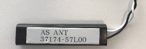
KBRK63T0
Aug 19, 2020Keyless Start System (LF Transmitter)
Equipment Class
DCD - Part 15 Low Power Transmitter Below 1705 kHz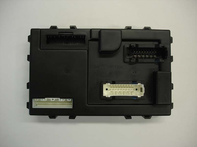
KBRBN009
Jan 19, 2010Automotive Entry System
Equipment Class
DCD - Part 15 Low Power Transmitter Below 1705 kHz
KBRTS003
Jan 20, 2005Vehicle Door Lock Transceiver
Equipment Class
DSR - Part 15 Remote Control/Security Device Transceiver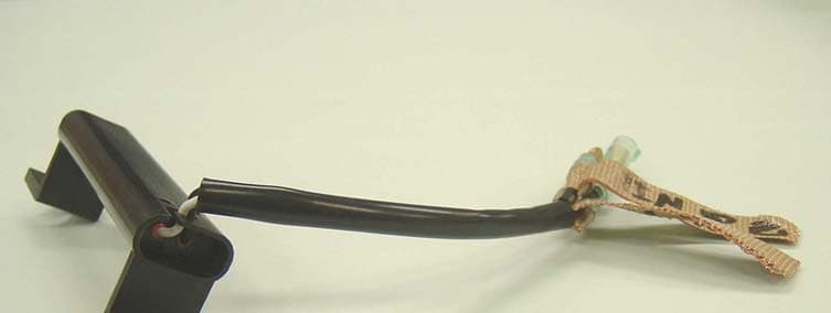
KBRS64J3
Jan 20, 2005Vehicle Door Lock Transceiver
Equipment Class
DCD - Part 15 Low Power Transmitter Below 1705 kHz