KBRMSUB13Keyless Entry Transmitter
Marelli Corporation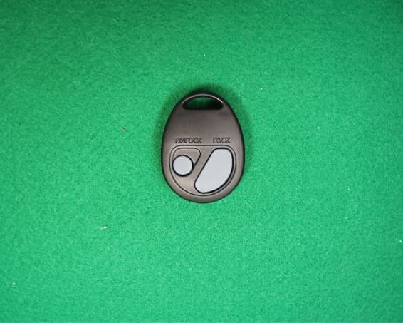
Click to zoom
Application Details
- Equipment Class
- DSC - Part 15 Security/Remote Control Transmitter
- Date of Grant
- Oct 20, 2001
- Application Purpose
- Original Equipment
- Date of Application
- Oct 20, 2001
- Equipment Note
- Keyless Entry Transmitter
- Frequency Range
- 314.85000000 - 314.85000000
- Company
- Marelli Corporation
- Country
- Japan
Documents & Files
Document Text
Text extracted from the exhibit documents filed with the FCC. Open a document above to read the original.
External Photos
External Photos FCC ID: KBRMSUB13 FCC ID: KBRMSUB13
Internal Photos
Internal Photos FCC ID: KBRMSUB13 FCC ID: KBRMSUB13 FCC ID: KBRMSUB13
Test Report
Test report Our reference : 21LE0042-YW-1 Page: 2 of 11 Issued date: October 18, 2001 FCC ID: KBRMSUB13 Testing Laboratory A-pex International Co., Ltd. Telephone:+81 596 39 1485 108 Yokowa-cho, Ise-shi Mie-ken 516-1106 JAPANFacsimile:+81 596 39 0232 Table of Contents Page 1 GENERAL INFORMATION3 1.1 Product Description4 1.2 Test Specification4 1.3 Methods & Procedures4 1.4 Test Location4 2 SYSTEM TEST CONFIGURATION5 2. 1 Operation Environment 5 2.2 Justification5 2. 3 EUT Exercise Software5 2.4 Test Procedure5 Figure 2.1 Configuration of Tested System6 3 RADIATED EMISSION DATA7 3.1 Field Strength Calculation7 2.2 –20dB Bandwidth7 3.3 Measurement Uncertainty8 4 TEST EQUIPMENT USED9 5 MEASUREMENT PHOTOS 10 Figure 5.1 Radiated Measurement Photos 10 APPENDIX 11 A:Test Data A1 – A3 Test report Our reference : 21LE0042-YW-1 Page: 3 of 11 Issued date: October 18, 2001 FCC ID: KBRMSUB13 Testing Laboratory A-pex International Co., Ltd. Telephone:+81 596 39 1485 108 Yokowa-cho, Ise-shi Mie-ken 516-1106 JAPANFacsimile:+81 596 39 0232 1 GENERAL INFORMATION APPLICANT: Calsonic Kansei Corporation ADDRESS: 5-24-15 Minamidai, Nakano-ku, Tokyo 164-8602 Japan Telephon Number: +81-3-5385-0111 Facsimile Number: +81-3-3383-1171 REGULATION(S): FCC Part 15 Subpart C Section 15.231 MODEL NUMBER: MSUB13 FCC ID: KBRMSUB13 SERIAL NUMBER: Sample No.1 CONDITION OF EUT: Engineering Prototype KIND OF EQUIPMENT: Keyless Entry System (Transmitter) TESTED DATE: July 13, 2001 RECEIPT DATE OF SAMPLE : July 12, 2001 REPORT FILE NUMBER: 21LE0042-YW-1 TEST SITE: A-PEX Yokowa No.3 Open Test Site Test report Our reference : 21LE0042-YW-1 Page: 4 of 11 Issued date: October 18, 2001 FCC ID: KBRMSUB13 Testing Laboratory A-pex International Co., Ltd. Telephone:+81 596 39 1485 108 Yokowa-cho, Ise-shi Mie-ken 516-1106 JAPANFacsimile:+81 596 39 0232 1.1 Product Description Model: MSUB13 (referred to as the EUT in this report) is a Keyless Entry System (Transmitter). The specification is as following : Carrier Frequency : 314.85 MHz Modulation: FSK Other Clock Frequency: 8.18MHz Information antenna: Integral / P.C.B pattern antenna Operation Voltage: Lithium Battery DC 3.0V(CR1620) 1.2 Test Specification Test Specification: FCC Part 15 Subpart C Title: FCC 47CFR Part15 Radio Frequency Device Subpart C Intentional Radiators 15.231 Periodic operation in the band 40.66 – 40.70 MHz and above 70MHz 1.3Methods & Procedures No.ItemTest ProcedureSpecificationRemarks 1 Electric Field Strength of Fundamental Emission ANSI C63.4:1992 15.231 3m 2 Electric Field Strength of Spurious Emission ANSI C63.4:1992 15.205 15.209 15.231 3m 3-20dB BandwidthANSI C63.4:1992 15.231 3m 1.4 Test Location A-PEX International Co.,Ltd. Yokowa No.3 test site 108 Yokowa-cho, Ise-shi, Mie-ken 516-1106 Japan Telephone number: +81-596-39-1485 Facsimile number: +81-596-39-0232 This site has been fully described in a report submitted to FCC office, and listed on September 12, 2000 (Registration number: 90412). *NVLAP Lab. code : 200109-0 Test report Our reference : 21LE0042-YW-1 Page: 5 of 11 Issued date: October 18, 2001 FCC ID: KBRMSUB13 Testing Laboratory A-pex International Co., Ltd. Telephone:+81 596 39 1485 108 Yokowa-cho, Ise-shi Mie-ken 516-1106 JAPANFacsimile:+81 596 39 0232 2 SYSTEM TEST CONFIGURATION 2.1 Operation Environment Temperature: See data Humidity: See data 2.2 Justification The system was configured in typical fashion (as a customer would normally use it) for testing. 2.3 EUT Exercise Software The EUT exercise program used during radiated testing was designed to exercise the various system components in a manner similar to typical use. The sequence is used: Operation Mode : Transmitting 2.4 Test Procedure Tabletop Equipment Radiated Emissions EUT was placed on a platform of nominal size, 1m by 1m, raised 80cm above the conducting ground plane. Test was made with the antenna positioned in both the horizontal and vertical planes of polarization. The measurement antenna was varied in height above the conducting ground plane to obtain the maximum signal strength. The measurement distance was 3m. Test report Our reference : 21LE0042-YW-1 Page: 6 of 11 Issued date: October 18, 2001 FCC ID: KBRMSUB13 Testing Laboratory A-pex International Co., Ltd. Telephone:+81 596 39 1485 108 Yokowa-cho, Ise-shi Mie-ken 516-1106 JAPANFacsimile:+81 596 39 0232 Figure2.1 Configuration of Tested System Front View (A):EUT Top View (A):EUT *Test data was taken under worse case conditions. No.ItemModel numberSerial numberManufacturerFCC ID A Keyless Entry System (Transmitter) MSUB13 Sample No.1Calsonic Kansei Corp KBRMSUB13 Test report Our reference : 21LE0042-YW-1 Page: 7 of 11 Issued date: October 18, 2001 FCC ID: KBRMSUB13 Testing Laboratory A-pex International Co., Ltd. Telephone:+81 596 39 1485 108 Yokowa-cho, Ise-shi Mie-ken 516-1106 JAPANFacsimile:+81 596 39 0232 3 RADIATED EMISSION DATA The initial step in collecting radiated data was a spectrum analyzer peak scan of the measurement range (30MHz-3200MHz). The final data was reported in the worst-case emissions. The minimum margin to the limit is as follows : No Ant Pol Freq [MHz] Reading [dB ì V] Antena Facter [dB] Cable Loss [dB] ATT [dB] AMP Gain [dB] Result [dB ì V/m] Limit [dB ì V/m] Margin [dB] Remark 1 H 314.850 62.4 14.4 3.6 5.8 27.6 58.6 75.6 17.0Fundamental 2 V2519.288 43.6 31.6 7.2 - 34.5 47.9 54.0 7.7Spurious Remark Below 1GHz: Test Receiver Setting: QP Detect / IF Band width 120kHz Above 1GHz: Spectrum Analyzer Setting: PK Detect / RBW 1MHz, VBW 1MHz 3.1 Field Strength Calculation The field strength is calculated by adding the Antenna Factor, Cable Factor and Antenna Pad, and subtracting the Amplifier Gain from the measured reading. The sample calculation is as follows : FS = RA + AF + CF + AT - AG where FS = Field Strength RA = Receiver Amplitude AF = Antenna Factor CF = Cable Factor AT = Antenna Pad AG = Amplifier Gain Assume a receiver reading of 62.4 dB V is obtained. The antenna Factor of 14.4 dB, Cable F…
Text truncated - open the document above for the full version.
Test Setup Photos
Test report Our reference : 21LE0042-YW-1 Page: 10 of 11 Issued date: October 18, 2001 FCC ID: KBRMSUB13 Testing Laboratory A-pex International Co., Ltd. Telephone:+81 596 39 1485 108 Yokowa-cho, Ise-shi Mie-ken 516-1106 JAPANFacsimile:+81 596 39 0232 5 RADIATED MEASUREMENT PHOTOS 5.1 Radiated Measurement Photos
Contact Information
Applicant
Takaichiro Ishida
Technical Contact
A-Pex International Co LtdMakoto Kosaka
[email protected]81-596-39-1485
108 Yokowa-cho · Ise-shi, Mie-ken · Japan
Non-Technical Contact
A-Pex InternationalMotomu Kawano
[email protected]81-596-24-8116
Test Firm
UL Japan, Inc.Kazunori Nishimura
Technical Specifications
| # | Rule Parts | Frequency Range | Power Output |
|---|---|---|---|
| 1 | 15.231 | 314.85 MHz - 314.85 MHz | - |
Other Applications from Marelli Corporation

KBRR55T0
Jun 30, 2021SW ASSY-SMART KEYLESS
Equipment Class
DSC - Part 15 Security/Remote Control Transmitter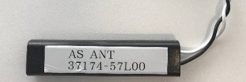
KBRK63T0
Aug 19, 2020Keyless Start System (LF Transmitter)
Equipment Class
DCD - Part 15 Low Power Transmitter Below 1705 kHz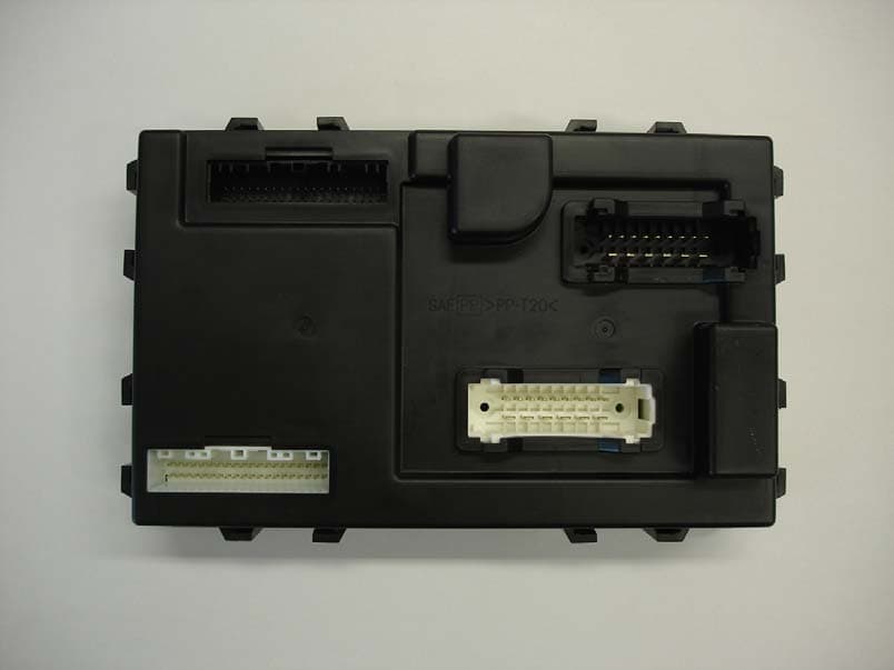
KBRBN009
Jan 19, 2010Automotive Entry System
Equipment Class
DCD - Part 15 Low Power Transmitter Below 1705 kHz
KBRTS003
Jan 20, 2005Vehicle Door Lock Transceiver
Equipment Class
DSR - Part 15 Remote Control/Security Device Transceiver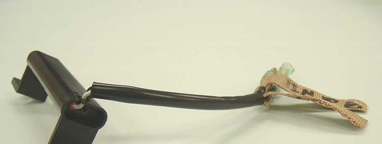
KBRS64J3
Jan 20, 2005Vehicle Door Lock Transceiver
Equipment Class
DCD - Part 15 Low Power Transmitter Below 1705 kHz