KIN915BWireless Modem Module
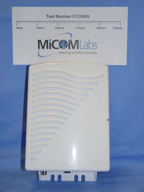
Wave Wireless Corporation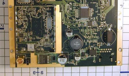
Click to zoom
Application Details
- Equipment Class
- DTS - Digital Transmission System
- Date of Grant
- Sep 24, 2006
- Application Purpose
- Original Equipment
- Date of Application
- Sep 24, 2006
- Equipment Note
- Wireless Modem Module
- Frequency Range
- 905.00000000 - 925.00000000
- Company
- Wave Wireless Corporation
- Country
- United States
Documents & Files
Document Text
Text extracted from the exhibit documents filed with the FCC. Open a document above to read the original.
Users Manual
LMS3000 Technical Note Lawrence Gordon Page 1 of 9 Last saved on 14-Sep-06 4:52 PM F:\Tech Notes\TN138A - 915B Radio Operational Requirements.doc Number: TN138A Title: 915B Radio Operational Requirements Author: Lawrence Gordon Reviewer: Date: 12-Sep-06 Pages: 9 Abstract: This document lists the requirements that must be met in order to use the Wave Wireless 915B Radio in different packages and configurations. Revision History: Date Rev. Author Comments 12-Sep-06 A LAG Add details on Tiltek antenna (2.5) Add table (2) listing antenna manufactureres and models Correct table (3) for Log-periodic gain and requred cable losses. Add table (4) for indoor antenna required cable losses Correct warning on outdoor antennas (2.1.3) TN138A 915B Radio Operational Requirements Lawrence Gordon Page 2 of 9 Last saved on 14-Sep-06 4:52 PM F:\Tech Notes\TN138A - 915B Radio Operational Requirements.doc Table of Contents 1 Introduction........................................................................................................................ 3 1.1 References ................................................................................................................ 3 2 Requirements....................................................................................................................3 2.1 Regulatory Notices Requirements ............................................................................ 3 2.1.1 FCC.................................................................................................................... 4 2.1.2 Industry Canada ................................................................................................ 5 2.1.3 Installation Warnings ......................................................................................... 5 2.2 Final Product Installation Guide Requirements ........................................................ 6 2.3 Final Product Labeling Requirements....................................................................... 6 2.4 Power Supplies ......................................................................................................... 6 2.5 Antennas................................................................................................................... 7 2.6 External RF Connectors............................................................................................ 7 3 Approved Configurations .................................................................................................. 8 3.1 Approved Power Supplies......................................................................................... 8 3.2 Approved Antennas................................................................................................... 8 Table of Tables Table 1 – Approved Power Supplies........................................................................................ 8 Table 2 – Tested Antennas......................................................................................................8 Table 3 – Cable Loss Requirements for Outdoor Antennas.................................................... 8 Table 4 – Cable Loss Requirements for Indoor Antennas ...................................................... 9 TN138A 915B Radio Operational Requirements Lawrence Gordon Page 3 of 9 Last saved on 14-Sep-06 4:52 PM F:\Tech Notes\TN138A - 915B Radio Operational Requirements.doc 1 INTRODUCTION The Wave Wireless 915B Radio is certified by FCC and Industry Canada (IC) under a Limited Modular Approval (FCC ID: KIN-915B and IC ID: 4309B-915B). This means that the radio can be used in various packages and configurations provided the requirements below are met. These requirements apply to any Wave Wireless final product using the 915B radio. Note that this radio under the 915B certifications cannot be sold as a bare board to end-customers or OEMs. Only Wave Wireless manufactured final products can be sold. As such, this document is intended only for Wave Wireless or its contractors to act as an ‘installation guide’ for installing the 915B radio into a final product. Adhering to these requirements will not necessarily ensure compliance to FCC and IC requirements for the final product. If there are any concerns, testing should be done to ensure compliance. For example, the 915B radio meets the FCC and IC Class B unintentional radiator requirements as a standalone unit. If it is combined with other components or radios, the aggregate may not meet the same limits as the standalone unit. The term “final product” in this document will refer to the product that is sold that incorporates the 915B radio. Wave Wireless products that use the 915B radio currently includes the CCU3100. This document will be updated as new configurations are approved for the 915B radio, such as new antenna and power supplies. The approved configurations are shown in Section 3. WARNING – Final product (e.g. CCU3100) user documentation (e.g. Installation Guides, Spec. Sheets) must NOT contain any information about how the 915B radio is installed in the final product nor how to access the radio. 1.1 References LMA PART 15 UNLICENSED MODULAR TRANSMITTER APPROVAL, DA 00-1407, June 26, 2000. Part 15 FCC CFR 47 Part 15 - RADIO FREQUENCY DEVICES, April 5, 2005. 2 REQUIREMENTS 2.1 Regulatory Notices Requirements Regulatory Notices This equipment has been tested and found to comply with the limits for a Class B Intentional Radiator, pursuant to Part 15 of the FCC Regulations. These limits are intended to provide pro- tection against harmful interference when the equipment is operated in a residential environment. This equipment generates, uses, and can radiate radio frequency energy and, if not installed and used in accordance with the instruction manual, may cause harmful interference to radio TN138A 915B Radio Operational Requirements Lawrence Gordon Page 4 of 9 Last saved on 14-Sep-06 4:52 PM F:\Tech Notes\TN138A - 915B Radio Operational Requirements…
Text truncated - open the document above for the full version.
Block Diagram
Corporate– Wave Wireless Corporation, 255 Consumers Road, Suite 500, Toronto, Ontario M2J 1R4 Phone: 416.502.3200 Fax: 416.502.2968 Calgary Office - Wave Wireless Corporation, Ste. 4, 6110-1A Street SW, Calgary, Alberta T2H 0G3, Phone/Fax: 403.253.5366 www.wavewireless.com 915B Block Diagrams The following are the block diagrams for the RF and digital sections of the Circuit Card Assembly for the 915B radio. The blocks shown are as follows: Top level RF section Ethernet PHY Microprocessor/MAC memory Microprocessor/MAC Baseband processor interface Block Diagrams Top Level Block Diagram Figure 1.1 – Top Level Block Diagram Corporate– Wave Wireless Corporation, 255 Consumers Road, Suite 500, Toronto, Ontario M2J 1R4 Phone: 416.502.3200 Fax: 416.502.2968 Calgary Office - Wave Wireless Corporation, Ste. 4, 6110-1A Street SW, Calgary, Alberta T2H 0G3, Phone/Fax: 403.253.5366 www.wavewireless.com RF Section Figure 1.2 – RF Section Block Diagram Corporate– Wave Wireless Corporation, 255 Consumers Road, Suite 500, Toronto, Ontario M2J 1R4 Phone: 416.502.3200 Fax: 416.502.2968 Calgary Office - Wave Wireless Corporation, Ste. 4, 6110-1A Street SW, Calgary, Alberta T2H 0G3, Phone/Fax: 403.253.5366 www.wavewireless.com Digital Section Ethernet PHY ETHERNET PHY BLOCK ICS ICS1893AF TP_TXP TP_TXN MDIO MDC TP_CT RXD3 TP_RXP RXD2 TP_RXN RXD1 RXD0 RXDV RXCLK RXER REF IN REF OUT TXCLK 10TCSR TXEN TXD0 TXD1 TXD2 TXD3 COL 100TCSR CRS RESET_N P2LI P1CL P3TD P0AC P4RD RESET_ETH TXD0 2 IDATA- ODATA+ ODATA- IDATA+ MDIO RXD3 2 TPA TPB 25MHz 2 k Ω 1% 3.3V MDC RXD2 RXD0 RXD1 RX_DV RX _CLK RX _ER TX _CLK TX _EN TXD1 TXD2 TXD3 COL CRS 1.54 k Ω 1% Pull-downPull-down Pull-down Link LED Pull-up Pull-up 100pF Activity LED 5.3.1 Ethernet PHY Block Diagram Corporate– Wave Wireless Corporation, 255 Consumers Road, Suite 500, Toronto, Ontario M2J 1R4 Phone: 416.502.3200 Fax: 416.502.2968 Calgary Office - Wave Wireless Corporation, Ste. 4, 6110-1A Street SW, Calgary, Alberta T2H 0G3, Phone/Fax: 403.253.5366 www.wavewireless.com Microprocessor/MAC Memory (FLASH,SDRAM) 5.3.2 Microprocessor/MAC Memory Block Diagram Corporate– Wave Wireless Corporation, 255 Consumers Road, Suite 500, Toronto, Ontario M2J 1R4 Phone: 416.502.3200 Fax: 416.502.2968 Calgary Office - Wave Wireless Corporation, Ste. 4, 6110-1A Street SW, Calgary, Alberta T2H 0G3, Phone/Fax: 403.253.5366 www.wavewireless.com Microprocessor/MAC To RF 32 11 RX_DV MDI MDC RSSI LED 3.3V SEL[1] PAPE RADIO_PE RX_PE GPIO[5] TX_PE SYNTH_DATA SYNTH_CLK SEL[0] PAPE UART_RTS GPIO[4] GPIO[2] UART_CTS GPIO[3] GPIO[1] GPIO[0] 4 To Ethernet To Memory 2.5V RXD3 MDO RXD2 RXD1 RXD0 RX_CLK RX _ER TX_CLK TX _EN TXD0 TXD1 TXD2 TXD3 COL CRS RESET _ETH JTAGSerial 4 12 BBTXPE PE1 PE2 CAL _EN RFSW M _SD_IF_RF M_SCLK_IF_RF M_LE_RF M_LE_IF RX_CLK RX _DATA MD_RDY TX _CLK TX _DATA TX _RDY CCA BB _RX_PE BB _TX_PE /RESET BB _CLK BB _DATA R/nW /CS_BBP To BBP Buffer MDIO Reset 3.3V 22MHz MDIO 5.3.3 Microprocessor/MAC Interface Block Diagram Corporate– Wave Wireless Corporation, 255 Consumers Road, Suite 500, Toronto, Ontario M2J 1R4 Phone: 416.502.3200 Fax: 416.502.2968 Calgary Office - Wave Wireless Corporation, Ste. 4, 6110-1A Street SW, Calgary, Alberta T2H 0G3, Phone/Fax: 403.253.5366 www.wavewireless.com BBP Interface BBP BLOCK TO RF IFDET TXI+/- TXQ+/- VREF RXI+/- RXQ+/- TXIFAGC RFIFAGC 2 2 2 2 3.3V 11MHz HFA3861B RX_CLK RX_DATA MD_RDY TX_CLK TX_DATA TX_RDY CCA BB_RX_PE BB_TX_PE /RESET BB_DATA BB_CL K R/nW /CS_BBP To MICRO /MAC ÷4 44MHz ÷2 22MHz ANTSEL RXRFAGC 5.3.4 BBP Interface Block Diagram
Cover Letter(s)
Corporate– Wave Wireless Corporation, 500-255 Consumers Road, Toronto, Ontario M2J 1R4 Phone: 416.502.3200 Fax: 416.502.2968 Calgary Office - Wave Wireless Corporation, Ste. 4, 6110-1A Street SW, Calgary, Alberta T2H 0G3, Phone/Fax: 403.253.5366 www.wavewireless.com 28 Aug 2006 Stuart Beck, Director of Certification, Nemko Canada Inc., 303 River Road, Ottawa, Ontario K1V 1H2 Dear Stuart, RE: Industry Canada Submission 4309B-915B and FCC Submission KIN-915B We are requesting that Nemko Canada review and certify our 915B Radio module as a Limited Modular Approval (LMA), Digital Transmission System under FCC Part 15 and RSS-210 with its three antenna types. We have worked with Mr. Russell Grant and yourself to ensure that the data being presented is correct and representative. We are submitting our test data in two reports, one from ETC/MPB Technologies and one from your lab, NEMKO Canada. • The ETC test report is a complete report for FCC and IC submission for an earlier version of the 915B radio module, with the testing for a unit in a metal chassis. In this test report and cover sheet, the units is referred to as the CCU3100, which is one of the products containing the 915B Radio Module. • The NEMKO test report provides test results on the current 915B radio module as a standalone bare module with no chassis. This test data shows that the 915B radio module can qualify under the LMA provisions of FCC and IC. It also shows that the test results for the antennas tested at ETC apply to the current 915B radio module The specific changes between the original 915B radio module as reported in the ETC test report and the current 915B radio module include: • Improved surge protection on the 48 VDC Power over Ethernet. • FLASH memory device – manufacturer discontinuation, using new part, same manufacturer. • Bandpass filters – manufacturer discontinuation, using new part, same manufacturer. • TX Amplifier and Mixer - manufacturer discontinuation of part that combined this functionality. Now using a separate mixer and amplifier. • LNA Amplifier and Mixer - manufacturer discontinuation, using new part, same manufacturer These changes required minor changes to resistors, capacitors and inductors to balance the new parts. Corporate– Wave Wireless Corporation, 500-255 Consumers Road, Toronto, Ontario M2J 1R4 Phone: 416.502.3200 Fax: 416.502.2968 Calgary Office - Wave Wireless Corporation, Ste. 4, 6110-1A Street SW, Calgary, Alberta T2H 0G3, Phone/Fax: 403.253.5366 www.wavewireless.com None of these changes have affected the tranmsmitted modulated waveform, bandwidth or power nor the unintentional emissions in receive mode. Testing at NEMKO has confirmed this. The following table identifies all the files in this joint FCC , IC submission. # Doc. Filename 1 Cover Letter 915B Cover Letter.pdf 2 IC application form (app/001) 4309B-915B Application for Certification.pdf 3 REL Acknowledgement Letter of Acknowledgement.pdf 4 FCC application form (app/003) KIN-915B Application for Certification.pdf 5 FCC Form 731 KIN-915B FCC form731.pdf 6 Confidentiality request letter Request for Confidentiality.pdf 7 LMA Letter 915B Request for Limited Module Approval.pdf 8 Block diagram 915B Radio Block Diagrams.pdf 9 Operational description 915B Functional Overview.pdf 10 Internal Photos 915B Radio Module Photos.pdf 11 Antenna Spec - Omni WavcAntSku305-0115_BCD-87010-25.pdf 12 Antenna Spec - log Periodic sc9014spec.pdf 13 Antenna Spec - Stacked Dipole WavcAntSku305-0131_TA-926VH-8-120.pdf 14 Schematics 915B_Schematic_confidential.pdf 15 Parts List 915B_BOM_confidential.pdf 16 User's Guide with warnings TN138 - 915B Radio Operational Requirements.pdf 17 Label format and location diagram 915B Product Label.pdf 18 RF Safety RSS 102 declaration 4309B-915B Declaration of Compliance to RSS102.pdf 19 RF Safety Exhibit 915B RF exposure.pdf 20 Test Report Cover page w08e3557 IC cover sheet.pdf 21 Test Report w08e3557-1 r2.pdf 22 Test Photos 915B Test Setup Pictures.pdf Some of the submissions refer to the CCU3100, which is the 915B Radio in a chassis, or the EUM3006A, which is the name of the printed circuit card assembly that is the 915B Radio Module with a specific antenna connector. A note on the company and the company identifiers we are using for this submission. Previous submissions have been in the name of WaveRider Communications, using FCC identifier OOX and IC identifier 3225B. In March 2006, WaveRider Communications and all its subsidiaries merged with Wave Wireless Corp. of San Jose, CA. The joint company uses the Wave Wireless Corp. name and holds ALL intellectual property of the original companies. Wave Wireless Corp. has FCC identifier KIN and IC identifier 4309. For this submission, it has been decided to use the Wave Wireless identifiers. Corporate– Wave Wireless Corporation, 500-255 Consumers Road, Toronto, Ontario M2J 1R4 Phone: 416.502.3200 Fax: 416.502.2968 Calgary Office - Wave Wireless Corporation, Ste. 4, 6110-1A Street SW, Calgary, Alberta T2H 0G3, Phone/Fax: 403.253.5366 www.wavewireless.com We look forward to answering any questions you have. Your Truly, Lawrence Gordon, Senior Technical Design Lead, WaveRider Communications (Canada) Inc. Suite 4, 6110 - 1A St. SW, Calgary, Alta, T2H 0G3 Tel/FAX: (403) 253-5366, Tel: (403) 616-5668(cell)
Cover Letter(s)
Corporate– Wave Wireless Corporation, 500-255 Consumers Road, Toronto, Ontario M2J 1R4 Phone: 416.502.3200 Fax: 416.502.2968 Calgary Office - Wave Wireless Corporation, Ste. 4, 6110-1A Street SW, Calgary, Alberta T2H 0G3, Phone/Fax: 403.253.5366 www.wavewireless.com 28 Aug 2006 Stuart Beck, Director of Certification, Nemko Canada Inc., 303 River Road, Ottawa, Ontario K1V 1H2 Dear Stuart, RE: Industry Canada Submission 4309B-915B and FCC Submission KIN-915B Wave Wireless is applying for a Limited Modular Approval for the 915B radio, since we expect to use this radio in several final products. These final products will all be manufactured by Wave Wireless only. This letter should provide sufficient justification for both FCC and IC. In accordance with FCC directive DA 00-1407 (June 26, 2000) “Part 15 Unlicensed Modular Transmitter Approval”, I have addressed each of the numbered requirements below. Those that apply to IC’s RSS-Gen Issue 1 Sept. 2005, section 7.1.1 are marked with an asterisk and the relevent paragraph number in 7.1.1. 1. “The modular transmitter must have its own RF shielding”. (*1) There are two shields on the radio, one covering the receiver and transmitter circuitry and one covering the local oscillator. Proof that these shields prevent coupling of the RF circuitry and any wiring is provided in the test report showing the results of testing the bare circuit card assembly without any housing. 2. “The modular transmitter must have buffered modulation/data inputs”. (*2) The radio accepts data from an Ethernet port only. The radio processors buffer this data and generate modulated signals internally to the radio. The user cannot over modulate or exceed the data rates set by the RF design. 3. “The modular transmitter must have its own power supply regulation”. (*3 which also require its own local reference oscillator). The 915B uses an external AC to 48 VDC power supply to regulate all power coming from the AC lines before it gets to the Circuit Card Assembly. This power supply is included in all testing of this radio. It provides isolation between the radio and the AC lines. Beyond that, there are voltage regulators and power filters on-board the radio to reduce any conducted emissions to the 48 VDC line. Furthermore, the 915B has its own local reference oscillator, which is located under its own RF shield. 4. “The modular transmitter must comply with the antenna requirements of Section 15.203 and 15.204(c)”. Versions of the 915B radio and its final products may use standard RF connectors requiring Professional Installations only. It is for this reason alone that we are applying for a Limited Modular Approval instead of a full modular approval. a. For IC only: “The certification submission contains a detailed description of the configuration of all antennas that will be used with the module”. (*4) This submission includes three antennas, which are detailed in the functional overview as well as the document “TN138 – 915B Radio Operational Requirements”. As well the data sheets for the 3 antennas used for testing are included. We are aware Corporate– Wave Wireless Corporation, 500-255 Consumers Road, Toronto, Ontario M2J 1R4 Phone: 416.502.3200 Fax: 416.502.2968 Calgary Office - Wave Wireless Corporation, Ste. 4, 6110-1A Street SW, Calgary, Alberta T2H 0G3, Phone/Fax: 403.253.5366 www.wavewireless.com that we require a permissive change to our certification before we can use other antenna types with this radio, although antennas of the same type but lower gain than those in this submission are permissible. 5. “The modular transmitter must be tested in a stand-alone configuration”. The 915B is tested as a bare circuit card assembly (CCA). AC power is passed to the AC to 48 VDC power supply and hence to the CCA. The power supply is specified as a necessary accessory for this radio. All testing includes the power supply. 6. “The modular transmitter must be labeled with its own FCC ID number, and, if the FCC ID is not visible when the module is installed inside another device, then the outside of the device into which the module is installed must also display a label referring to the enclosed module”. See “FCC - 915B Product Label.pdf”, submitted as part of the documentation package, to see the format and location of both the label on the radio itself as well as label on the packaged radio. 7. “The modular transmitter must comply with any specific rule or operating requirements applicable to the transmitter and the manufacturer must provide adequate instructions along with the module to explain any such requirements”. See “TN138 – 915B Radio Operational Requirements”, submitted as part of the documentation package, for specific requirements, such as antenna types acceptable, installation requirements, etc. 8. “The modular transmitter must comply with any applicable RF exposure requirements”. See “TN138 – 915B Radio Operational Requirements”, submitted as part of the documentation package, for specific requirements, such as antenna types acceptable, required cable losses and separation requirements. Wave Wireless is applying for a Limited Module Approval for the 915B since future versions of this product will be completely under Wave Wireless’s control by being the manufacturer and integrator ourselves. Furthermore, all manuals or installations guides for these products warn the user that there are no servicable parts inside the product and opening the product will void any warranties. All of this is clearly spelled out in the document “TN138 – 915B Radio Operational Requirements”. Your Truly, Lawrence Gordon, Senior Technical Design Lead, Wave Wireless Communications (Canada) Inc. Suite 4, 6110 - 1A St. SW, Calgary, Alta, T2H 0G3 Tel/FAX: (403) 253-5366, Tel: (403) 616-5668(cell)
External Photos
915B Radio Module Photos Top Side with shield on 610234FCC ID: KIN-915B IC: 4309B-915B 621234 Top side under shield detail 610234FCC ID: KIN-915B IC: 4309B-915B 621234 Bottom side with shield on Bottom side, shield off, radio detail.
ID Label/Location Info
Corporate– Wave Wireless Corporation, 255 Consumers Road, Suite 500, Toronto, Ontario M2J 1R4 Phone: 416.502.3200 Fax: 416.502.2968 Calgary Office - Wave Wireless Corporation, Ste. 4, 6110-1A Street SW, Calgary, Alberta T2H 0G3, Phone/Fax: 403.253.5366 www.wavewireless.com 13 Sep 2006 To Whom It May Concern: Reference: FCC ID "KIN-915B" and IC “4309B-915B” Labeling The drawing below represents the label for the 915B PCBA (printed circuit board assembly), showing the FCC and Industry Canada IDs. This label will appear on all 915B boards. REV.DESCRIPTIONDATEBY D C B A 4321 D C B A 4321 V2Add Model Number13Sep06LAG 1.50 0.43 Label as shown: Text - Arial 8 pt Black Barcode - IDAutomationSC128S (Code 128) Material - White Polyester Adhesive - Able to withstand -40 to +70C Manufacturer can alter barcode font and text font provided relative locations and text are preserved and text is clearly legible. to scale 2x scale DESCRIPTION For use on EUM3006A/CCU3100 PCBA DRAWN BY LAWRENCE GORDON PAGE 1 OF 1 TITLE 915B Radio PCBA Label FILENAME REVISED 13-Sep-2006 621234 610234 Model 915B FCC ID: KIN-915B IC: 4309B-915B 621234 610234 Model 915B FCC ID: KIN-915B IC: 4309B-915B Corporate– Wave Wireless Corporation, 255 Consumers Road, Suite 500, Toronto, Ontario M2J 1R4 Phone: 416.502.3200 Fax: 416.502.2968 Calgary Office - Wave Wireless Corporation, Ste. 4, 6110-1A Street SW, Calgary, Alberta T2H 0G3, Phone/Fax: 403.253.5366 www.wavewireless.com The location of the label on the board is left to the manufacturer. The following picture shows a typical placement. 621234 610234 Model 915B FCC ID: KIN-915B IC: 4309B-915B Corporate– Wave Wireless Corporation, 255 Consumers Road, Suite 500, Toronto, Ontario M2J 1R4 Phone: 416.502.3200 Fax: 416.502.2968 Calgary Office - Wave Wireless Corporation, Ste. 4, 6110-1A Street SW, Calgary, Alberta T2H 0G3, Phone/Fax: 403.253.5366 www.wavewireless.com The label shown below is an example of the final product label that could be used for products that contain the 915B radio. Such labels will be prominently displayed on the outside of any product containing the 915B PCBA. In conformance with FCC and IC requirements, the label shows that the final product “Contains” the 915B radio using the FCC and IC identifiers for it. Note that Wave Wireless Corp has merged with WaveRider Inc., so the WaveRider name and logo can be used for Wave Wireless products. The label below is approximately twice the size of the actual label. CCU3100 IAB0 CCU3100IAB0A612624321 PRODUCT: VERSION: Contains FCC ID: KIN-915B Made in Canada / Fabrique au Canada This device complies with Part 15 of the FCC rules. Operation is subject to the following conditions: 1) This device may not cause harmful interferance and 2) This device must accept any interference received, including interference that may cause undesired operation. WWW.WAVEWIRELESS.COM COMMUNICATIONS INC. CCU3100IAB0A612624321 CUS Contains IC: 4309B-915B The label is composed of: MATERIAL - Thermal Transfer Matte Silver Polyester Label Material: 3M P/N 3M7872 ADHESIVE - Acrylic Adhesive: 3M P/N: #350 LINER - #55 Densified Kraft Your Truly, Lawrence Gordon, Senior Technical Design Lead, Wave Wireless Corporation, Suite 4, 6110 - 1A St. SW, Calgary, Alta., Canada, T2H 0G3 Tel: (403) 770-1026 or (416) 848-1746, Office Tel/FAX: (403) 253-5366, Tel: (403) 616-5668(cell)
Internal Photos
915B Radio Module Photos Top Side with shield on 610234FCC ID: KIN-915B IC: 4309B-915B 621234 Top side under shield detail 610234FCC ID: KIN-915B IC: 4309B-915B 621234 Bottom side with shield on Bottom side, shield off, radio detail.
Operational Description
Corporate– Wave Wireless Corporation, 500-255 Consumers Road, Toronto, Ontario M2J 1R4 Phone: 416.502.3200 Fax: 416.502.2968 Calgary Office - Wave Wireless Corporation, Ste. 4, 6110-1A Street SW, Calgary, Alberta T2H 0G3, Phone/Fax: 403.253.5366 www.wavewireless.com 1 915B FUNCTIONAL OVERVIEW The 915B is a 900MHz radio module intended to provide connectivity between an end-user’s computer and an Internet Service Provider. It is a single PCB wireless solution based on the Intersil PRISM II Direct Sequence Chip Set. The 915B is functionally equivalent to the 915A PCBA (previously certified with FCC ID: OOX-915A), the EUM3006/E3K6 (OOX-E3K6), the MMT9000 (OOX-WMAN), in regards to frequency of operation, output power, and modulation scheme. The 915B is intended for mounting in variety of chassis, including an aluminum enclosure for external mounting as a base station. 1.1 Overall functionality The 915B consists of two main sections; the digital and the RF section. Block diagrams for both sections can be found in the document “915B Block Diagrams”. The digital section contains the following functionality: 1. I/O 2. Ethernet PHY 3. Microprocessor/MAC 4. Memory 5. Power Regulation The radio module’s RF section contains the following functionality: 1. Baseband Processor 2. Modulator/Demodulator (with IF synthesizer) 3. RF Synthesizer 4. Up Converter 5. Power Amplifier 6. Low Noise Amplifier (LNA) 7. Down Converter 8. RF VCO 9. IF VCO 10. Reference Oscillator 11. Antenna (RF) Interface During transmission, data obtained by the Microprocessor from the I/O ports, is transferred to the MAC. The MAC reformats the data and places it on the Baseband Processor TX data line. This data is modulated using CCK modulation and then spread using a defined PN code such that the data is sent at a rate of 2.75Mbit/s. The data is preceded by a header that uses DPSK modulation. Corporate– Wave Wireless Corporation, 500-255 Consumers Road, Toronto, Ontario M2J 1R4 Phone: 416.502.3200 Fax: 416.502.2968 Calgary Office - Wave Wireless Corporation, Ste. 4, 6110-1A Street SW, Calgary, Alberta T2H 0G3, Phone/Fax: 403.253.5366 www.wavewireless.com Two signals are generated, the In-Phase (I) and Quadrature (Q) components. The I & Q signals are sent to the Modulator/Demodulator where they are first filtered and then modulated with the IF frequency (70 MHz). The IF oscillator generates a 140 MHz signal which is divided by two inside the Modulator/Demodulator and used to modulate the I & Q signals. The final IF signal of 70 MHz is then sent to the Up converter. The Up converter will shift this signal to the RF frequency for the channel programmed in the synthesizer, for operation within the 902-928 MHz ISM band. In the final stage, this signal is amplified to produce +27.3 dBm RF power as measured at the output of the antenna port. In receive mode, the radio signal is amplified by the LNA, and then sent to the Down converter. The Down converter converts this signal from the 902-928 MHz range to the IF frequency, 70 MHz. The Modulator/Demodulator then converts the signal to baseband and splits the signal into its I & Q components, before sending it to the Baseband Processor. Finally, the Baseband Processor despreads and demodulates the data contained in the CCK format, and places it on the RX data line to the MAC. The MAC modifies the data, then transfers it to the Microprocessor which reformats the information and sends it out the I/O ports. The RF and IF Local Oscillator signals are generated using the synthesizers and voltage controlled oscillators. The RF synthesizer is programmed with the desired RF channel frequency plus the IF frequency. The IF synthesizer in the Modulator/Demodulator is programmed with 140MHz. The baseband processor and the synthesizer are driven from a common 44 MHz oscillator to control the timing of these chips. Example (for Channel 1 operation): RF IF LO 905 MHz + 70 MHz = 975 MHz 1.2 Output Power Each 915B is calibrated at 905, 915 and 925 MHz during manufacturing to output the 27.3 dBm power at the antenna connector. The maximum time the transmitter is on is 5.1 msec after which it is in receive mode for at least 0.9 msec, so that the max. duty cycle is 5.1/6.0 = 85%. This duty cycle is not under the control of the user, but is inherent in the Dynamic Polled MAC used to control access to the channel. 1.3 Antennas The antennas being cerified with the 915B board include: • Omni-Directional Dipole – 10 dBd / 12.15 dBi • Log-periodic Sector – 14 dBd / 16.15 dBi • Dipole array – 11.5 dBd / 13.65 dBi Corporate– Wave Wireless Corporation, 500-255 Consumers Road, Toronto, Ontario M2J 1R4 Phone: 416.502.3200 Fax: 416.502.2968 Calgary Office - Wave Wireless Corporation, Ste. 4, 6110-1A Street SW, Calgary, Alberta T2H 0G3, Phone/Fax: 403.253.5366 www.wavewireless.com There are two criteria on the max. EIRP for a Part 15 transmitter in the 902-928 MHz range: 1) Maximum of 36 dBm EIRP and 2) Max. of 0.603 mW/cm 2 for radiation exposure The min. separation distance to ensure RF exposure is acceptable for an EIRP of 36 dBm is 22.9 cm. Outdoor antennas are intended to be mounted in a permanent fixed location, where we require installers to provide at least 30 cm separation between people and the antenna. The following tables show antenna gains for each type of antenna and the associated antenna system gain including cable losses for installations to ensure that the 36 dBm EIRP outdoor requirement is met. The installer will de…
Text truncated - open the document above for the full version.
Contact Information
Applicant
Carl Lynch
Technical Contact
WaveWireless Corp.Lawrence Gordon
[email protected]403-253-5366
Ste. 4, 6110-1A Street SW · Calgary · Canada
Non-Technical Contact
WaveWireless Corp.Lawrence Gordon
[email protected]403-253-5366
Test Firm
Nemko Canada Inc. (Ottawa)Charles Neal
Technical Specifications
| # | Rule Parts | Frequency Range | Power Output |
|---|---|---|---|
| 1 | 15C | 905 MHz - 925 MHz | 540.00 mW |
Other Applications from Wave Wireless Corporation
KINSL9200
Nov 16, 20052.4, 5.8 & 4.9GHz (PSB) Wireless Router
Equipment Class
DTS - Digital Transmission System
KINSL9202
Oct 11, 2004Wireless LAN
Equipment Class
DTS - Digital Transmission System
KINSL9201
Sep 28, 2004SPEEDLAN WIRELESS LAN
Equipment Class
DTS - Digital Transmission System
KINAPG20FNET
Mar 13, 2002Wireless LAN, AIRPRO GOLD 20F.NET
Equipment Class
DSS - Part 15 Spread Spectrum Transmitter
KINDM2
Mar 29, 1999Wireless Data Link
Equipment Class
DSS - Part 15 Spread Spectrum Transmitter