KINSL92002.4, 5.8 & 4.9GHz (PSB) Wireless Router
Wave Wireless Corporation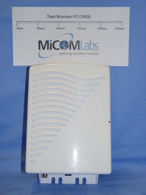
Click to zoom
Application Details
- Equipment Class
- DTS - Digital Transmission System
- Date of Grant
- Nov 16, 2005
- Application Purpose
- Original Equipment
- Date of Application
- Nov 16, 2005
- Equipment Note
- 2.4, 5.8 & 4.9GHz (PSB) Wireless Router
- Frequency Range
- 5745.00000000 - 5825.00000000
- Company
- Wave Wireless Corporation
- Country
- United States
Documents & Files
Document Text
Text extracted from the exhibit documents filed with the FCC. Open a document above to read the original.
Users Manual
Wave Wireless Wave Wireless Copyright Statement (c) 2005. Wave Wireless Corp. provides this Installation Guide without warranty of any kind, either express or implied, including, but not limited to, the implied warranties of merchantability and fitness for a particular purpose. Wave Wireless Corp. may make improvements and changes to the product described in this manual at any time and without any notice. Wave Wireless Corp. assumes no responsibility for its use, nor any infringements of patents or other rights of third parties that would result. This publication may contain technical inaccuracies or typographical errors. Periodic changes are made to the information contained herein. These changes, and mechanical corrections, will be incorporated in subsequent revision levels of the publi- cation. No part of this publication may be stored in a retrieval system, transmitted, or reproduced in any way, including but not limited to photocopy, photograph, magnetic or other records, without the prior written permission of Wave Wireless Corp. All other brand and product names are the trademarks of their respective holders. Wa v e Wi r e l e s s 1996 Lundy Ave. San Jose, CA 95131 www.wavewireless.com Technical Support 408-943-4202 (phone) 408-943-4355 (fax) SPEEDLAN 9200 User Guide Part # 34357-MNL Rev. B Contents-1 CHAPTER 1 - Introduction Features and Benefits ....................................................................................................................................1-2 SPEEDLAN 9200 Features ..................................................................................................................1-2 ISP Functionality ..................................................................................................................................1-3 IP Router Functionality ........................................................................................................................1-3 Configuration Management ..................................................................................................................1-4 SPEEDManage .....................................................................................................................................1-4 Features (and Benefits) .........................................................................................................................1-4 Priority Queuing ...................................................................................................................................1-5 SNMP ...................................................................................................................................................1-6 Equipment and Hardware .....................................................................................................................1-7 SPEEDLAN 9200 Mesh Protocol -- How It Works in Mesh Cells ..............................................................1-7 SPEEDLAN’s Mesh Cell Architecture ................................................................................................1-9 SPEEDLAN 9200 Mesh Core Components .........................................................................................1-9 Neighbor Discovery .....................................................................................................................1-9 Topology Updates ........................................................................................................................1-9 Routing.......................................................................................................................................1-10 Why SPEEDLAN Outperforms Other Routing Equipment ......................................................1-10 Document Changes & Corrections/Firmware Updates ...............................................................................1-11 Contacting Technical Support .....................................................................................................................1-11 CHAPTER 2 - Hardware Rooftop and Tower Installations Warning ....................................................................................................2-2 Regulatory Information .................................................................................................................................2-2 Declaration of Conformity for RF Exposure.................................................................................................2-3 General Safety Requirements for Installation of SPEEDLAN 9200 Models ...............................................2-3 Hardware Overview ......................................................................................................................................2-4 Tips for Antenna Alignment ........................................................................................................2-5 Drawings of Outdoor, Remote-Mounted Components .................................................................................2-6 Indoor Junction Box .............................................................................................................................2-6 The SPEEDLAN 9201/9204 with an Integrated Omni-Directional .....................................................2-7 Bottom View of SPEEDLAN 9201/SPEEDLAN 9204 ......................................................................2-8 System Description ...............................................................................................................................2-8 Package Contents.................................................................................................................................2-8 Installation Steps for the SPEEDLAN 9201/SPEEDLAN 9204 ..........................................................2-9 Installation Diagram of the SPEEDLAN 9201/SPEEDLAN 9204 ....................................................2-11 The SPEEDLAN 9202/SPEEDLAN 9203…
Text truncated - open the document above for the full version.
Users Manual
SPEEDLAN 9200 User Guide Part # 34357-MNL Rev. B 4-5 Wireless menu Choose one of the options from the Wireless menu: •If you choose Configuration, you will be able to set the following radio parame- ters: SSID, wireless mode, channel, signaling rate, turbo mode, Tx power and preamble. For more information, see Configuration, page 3-44 for more details. •If you choose Tx Retries, you will be able to set the Transmit Retry Limit and Sig- naling Rate Fallback. For more information, see Max Tx Retries and Signaling Rate Fallback, Chapter 3. •If you choose Max Throughput, you will be able to set the Max Transmit Data Rate in Kb/s. For more information, see Max Throughput (Regulating Band- width), Chapter 3. •If you choose RTS/CTS and enable RTS/CTS for a particular node, it will refrain from sending a unicast data frame until the node completes the "RTS/CTS hand- shake" with the receiving node. For more information, see Request to Send (RTS) / Clear to Send (CTS), page 4-5. •If you choose Rx Threshold, you will be able to set the threshold for each mesh router on the network. For more information, see Receive (Rx) Threshold Param- eter, page 4-6 for details. •If you choose Blocked Links, you will be able to block or unblock mesh routers. For more information, see Blocked Links, page 4-8 for more details. •If you want to enter the number of times that a neighbor node can fail to reply to a neighbor discovery probe before it is declared unreachable, see Link Expiration, page 4-9. Request to Send (RTS) / Clear to Send (CTS) RTS/CTS allows you to fine-tune the operation of your wireless LAN. RTS/CTS will help minimize collisions between transmissions from hidden nodes on the wireless network. When you enable RTS/CTS for a particular node, it will refrain from sending a unicast data frame until the node completes the "RTS/CTS handshake" with the receiving node. Here is how the process works: Node A transmits a RTS frame. Node B, on the receiving end, retrieves the RTS and sends a response with a CTS frame. Before Node A sends the data frame, it must receive a CTS frame from Node B. Both the RTS and CTS frames contain the length of the data frame to Part # 34357-MNL Rev. B SPEEDLAN 9200 User Guide 4-6 alert other nodes to wait to access the network, while the node initiating the RTS sends its data. To enable RTS/CTS, choose RTS/CTS from the Wireless menu. The following screen will appear. Figure 4-4: RTS/CTS •To turn on RTS/CTS, click the Enabled option. •To turn off RTS/CTS, click the Disabled option. •Threshold: The minimum size (in bytes) of unicast data frames whose transmission will be preceded by a RTS/CTS handshake. The effective range is 50 through 1500. The optimal value depends on many factors , but a starting value of 100 is recommended. (The factors include the number of hidden nodes, the statis- tical distribution of frame lengths, and the amount of retransmissions caused by RF interference.) •Select those nodes for which you want to enable RTS/CTS and click the Apply to Selected Nodes button. Receive (Rx) Threshold Parameter From a single mesh unit connected to a mesh network, you can set the receive threshold (given in dBm), for every mesh router in the network. The receive threshold specifies the minimum acceptable receive level for a datagram (defined for signaling rates, depending on the Wireless Mode you selected on the Wireless Configuration page). Any datagrams SPEEDLAN 9200 User Guide Part # 34357-MNL Rev. B 4-7 received below these levels will be discarded. This will provide better network stability for networks containing marginal links, since link state changes (and the corresponding routing changes) will be avoided for marginal links which are not capable of consistent communication. By clicking the Defaults button, the values will go to their default values. If you enter a value of 0 (zero), you are turning the receive threshold parameter off. Figure 4-5: Rx Threshold page The current Rx thresholds for your wireless mesh router(s) are listed in the Current Rx Thresholds section. Their signaling rates are also listed, as described above. If you click Default, it will load the current default setting for the Configurator. Click Apply when finished. Part # 34357-MNL Rev. B SPEEDLAN 9200 User Guide 4-8 Blocked Links Figure 4-6: Blocking Mesh Routers This feature allows you to block all traffic from a specific hardware address. This is most often used when a marginal signal exists between two nodes in a mesh network, such that the network functions more reliably when no direct communication occurs between the nodes. To completely block a link you must perform the same action on the remote node. Note: If you blocked a mesh Link, the next time it is rebooted it will remain blocked. If you want to unblock the Link, make sure that the Blocked check box is not selected. Note: Click Apply when finished. Select the checkbox under Blocked to block a Link. Leave it unselected when you want to leave the Mesh Link unblocked. SPEEDLAN 9200 User Guide Part # 34357-MNL Rev. B 4-9 Link Expiration This page is only available for mesh routers. To use this feature, choose Link Expiration from the Wireless menu. The following page will appear: Figure 4-7: Link Expiration Neighbor Expiration Threshold: The number of consecutive missed neighbor discovery probes that cause the direct link formed by two neighbors to be declared unusable. If bi- directional traffic becomes possible in the future, the link will again become eligible for use. The range for this parameter is 3-15. The default is 7. After selecting a value for the parameter described above, select the nodes to which this value will be sent (via the Select All or Apply to Selected Nodes buttons). Then, click Apply. Part # 34357-MNL Rev. B SPEEDLAN 9200 User Guide 4-10 Admin Menu Remote Control To remotely reboot or turn off the SPEEDLAN 9200 mesh routers, choose Remote Control from the Admin menu. The following page will appear. Figure 4-…
Text truncated - open the document above for the full version.
Users Manual
SPEEDLAN 9200, PROFESSIONAL INSTALLATION GUIDELINES USER GUIDE ADDENDUM ADDITION TO 34357-MNL (FOR SPEEDLAN 9200, 2.4/5.8/4.9) Rev 01 SPEEDLAN Professional Installation Guidelines User Guide Addendum Table of Contents: 1. Background Information on the Installation of Speedlan 9200....................................................................2 2. 2.4 GHz SPEEDLAN 9200 Installation Requirements..................................................................................2 3. 5.8 GHz SPEEDLAN 9200 Installation Requirements..................................................................................3 4. 4.9 GHz SPEEDLAN 9200 Requirements.......................................................................................................3 1. Background Information on the Installation of Speedlan 9200 Wave Wireless requires a Professional Installer to install the Speedlan 9200 product The Speedlan 9200 was tested for compliance to the Federal Communication Commission (FCC) rules part 15.247 and the testing results indicated the need for some special guidelines for the Professional Installer to follow when installing the Speedlan 9200. 2. 2.4 GHz SPEEDLAN 9200 Installation Requirements The installer is to follow the diagram in Figure 2-5 of the Speedlan 9200 User guide, Wave Wireless part number 34357-MNL. 3. 2.4 GHz SPEEDLAN 9200 Installation Requirements The professional installer must follow the following guidelines in table 1 when installing the SPEEDLAN 9200 at 2.4 GHz. Wave Wireless Confidential 2 of 3 Rev 01 SPEEDLAN Professional Installation Guidelines User Guide Addendum Antenna Type (802.11g), MAX TXPO Setting: 24 dBi, Parabolic Grid +17 dBm, except +15 dBm on Channel 11 16 dBi, 90° Sector +17 dBm, except +14 dBm on Channel 1 & 11 15 dBi, Yagi +17 dBm, except +13 dBm on Channel 1 & 11 12 dBi OMNI +17 dBm, except +15 dBm on Channel 1 & 11 8 dBi Patch +17 dBm, except +15 dBm on Channel 1 and +17 dBm, except +14 dBm on Channel 11 For 802.11b, +17 dBm no TXPO restrictions 4. 5.8 GHz SPEEDLAN 9200 Installation Requirements The professional installer must follow the following guidelines in table 1 when installing the SPEEDLAN 9200 at 5.8 GHz Antenna Type (802.11a), MAX TXPO Setting: 29 dBi, Parabolic Grid +17 dBm, Band-Stop or Band Pass filter required before Antenna 23 dBi, Panel +17 dBm, Band-Stop or Band Pass filter required before Antenna 17 dBi, Backfire Parabolic +17 dBm, no restrictions 16 dBi, 120° Sector +17 dBm, no restrictions 8 dBi OMNI +17 dBm, no restrictions The installer is to follow the diagram in Figure 2-5 of the Speedlan 9200 User guide, Wave Wireless part number 34357-MNL. The filter is to installed directly on the antenna or in line with the lightning arrestor 5. 4.9 GHz SPEEDLAN 9200 Requirements The professional installer must follow the following guidelines in table 1 when installing the SPEEDLAN 9200 at 4.9 GHz: 4.9 GHz complies with Part 90, Subpart Y, As per 90.1215, the maximum antenna gain 9dBi for OMNI antennas. The maximum antenna gain is 26 dBi for directional antennas used in Point-to-Point or Point-to-Multipoint. For each dB increase in antenna gain over the above stated values, the transmit power must be reduced correspondingly Wave Wireless Confidential 3 of 3
External Photos
3922 Valley Avenue ‘Suite B’, Pleasanton, California 94566 USA Tel.: +1 925 462 0304, Fax: +1 925 462 0306 www.micomlabs.com Monday, October 31, 2005 PCOM08 – A1 – SPEEDLAN 9200 Wireless Mesh Router Wave Wireless Corporation SPEEDLAN 9200 4.9 GHz Public Safety Band Radio
External Photos
Page 1 of 6 EXTERNAL PHOTOS ANTENNAS Antenna 1: 2.4GHz, 8 dBi Patch Antenna 2: 2.4GHz, 12 dBi Dipole Page 2 of 6 Antenna 3: 2.4GHz, 15 dBi Yagi Antenna 4: 2.4GHz, 16 dBi 90 degree Sector Page 3 of 6 Antenna 5: 2.4GHz, 24 dBi Parabolic Grid Antenna 6: 5.8GHz, 10 dBi Dipole Page 4 of 6 Antenna 7: 5.8GHz, 16 dBi 120 degree Sector Page 5 of 6 Antenna 8: 5.8GHz, 17 dBi Backfire Parabolic Antenna 9: 5.8GHz, 23 dBi Panel Page 6 of 6 Antenna 10: 5.8GHz, 29 dBi, Parabol
ID Label/Location Info
CONFIDENTIAL INFORMATION FOR FCC FILING FCC Label for Speedlan 9200 Speedlan 9200 FCC Label Confidential 1 of 1
ID Label/Location Info
FCC LABEL LOCATION PHOTOGRAPH, SPEEDLAN MODEL 9200 FCC Label Photograp hLocation Speedlan 9200 FCC Label Location Photograph Confidential 1 of 1
RF Exposure Info
3922 Valley Avenue ‘Suite B’, Pleasanton, California 94566 USA Tel.: +1 925 462 0304, Fax: +1 925 462 0306 www.micomlabs.com Monday, October 31, 2005 WAVW01 – A1 SPEEDLAN 9200 Maximum Permissible Exposure Calculation FCC, Part 15 Subpart C §15.247(b)(5) Calculations for Maximum Permissible Exposure Levels Power Density = Pd (mW/cm 2 ) = EIRP/(4πd 2 ) EIRP = P * G P = Peak output power (mW) G = Antenna numeric gain (numeric) d = Separation distance (cm) Numeric Gain = 10 ^ (G (dBi)/10) 2.4 GHz 802.11g = Max. Output Power +22.01 dBm, 158.9 mW Max. Antenna Gain = 24 dBi, 251.2 numeric Min. Antenna Gain = 8 dBi, 6.3 numeric 5.8 GHz 802.11a = Max. Output Power +21.02 dBm, 126.5 mW Max. Antenna Gain = 29 dBi, 794.3 numeric Min. Antenna Gain = 10 dBi, 10.0 numeric The EUT belongs to the General Population/Uncontrolled Exposure, power density limit is 1.0mW/cm 2 Minimum Gain Antennas Freq. Band Antenna Gain (Numeric) Peak Output Power (mW) Calculated RF Exposure at d=20cm (mW/cm 2 ) Limit (mW/cm 2 ) 2.4 GHz 6.3 158.9 0.2 1 5.8 GHz 10 126.5 0.25 1 Maximum Gain Antennas – Calculated Safe Distance @ 1 mW/cm 2 Freq. Band Antenna Gain (Numeric) Peak Output Power (mW) Calculated Safe Distance (at 1 mW/cm 2 ) (cm) Limit (mW/cm 2 ) 2.4 GHz 251.2 158.9 56.4 1 5.8 GHz 794.3 126.5 89.4 1
Test Report
Test of SPEEDLAN 9200 To FCC 47 CFR Part 15.247 Test Report Serial No.: WAVW01-A1 Rev A TEST REPORT FROM Test of SPEEDLAN 9200 To FCC 47 CFR Part 15.247 Test Report Serial No.: WAVW01-A1 Rev A This report supersedes None Manufacturer: Wave Wireless Corporation 1996 Lundy Avenue San Jose, CA 95131 USA Product Function: Wireless Mesh Router Operating at 2.4 GHz and 5.8 GHz Copy No: pdf Issue Date: 27th Oct 2005 This Test Report is Issued Under the Authority of; MiCOM Labs, Inc. 3922 Valley Avenue, Suite B Pleasanton, CA 94566 USA Phone: +1 (925) 462-0304 Fax: +1 (925) 462-0306 www.micomlabs.com CERTIFICATE #2381.01 MiCOM Labs is an ISO 17025 Accredited Testing Laboratory This test report may be reproduced in full only. The document may only be updated by MiCOM Labs personnel. Any changes will be noted in the Document History section of the report. Title: SPEEDLAN 9200 To: Serial #: Issue Date: Page: FCC 47 CFR Part 15.247 WAVW01-A1 Rev A 27th Oct 2005 2 of 113 This test report may be reproduced in full only. The document may only be updated by MiCOM This page has been left intentionally blank Labs personnel. Any changes will be noted in the Document History section of the report. MiCOM Labs, 3922 Valley Avenue, Suite B, Pleasanton, CA 94566 USA, Phone: 925.462.0304, Fax: 925.462.0306, www.micomlabs.com Title: SPEEDLAN 9200 To: Serial #: Issue Date: Page: FCC 47 CFR Part 15.247 WAVW01-A1 Rev A 27th Oct 2005 3 of 113 This test report may be reproduced in full only. The document may only be updated by MiCOM TABLE OF CONTENTS ACCREDITATION & LISTINGS.........................................................................................4 1. TEST RESULT CERTIFICATE.....................................................................................7 2. REFERENCES AND MEASUREMENT UNCERTAINTY...........................................8 2.1. Normative References..................................................................................................8 2.2. Test and Uncertainty Procedures.................................................................................8 3. PRODUCT DETAILS AND TEST CONFIGURATIONS..............................................9 3.1. Technical Details..........................................................................................................9 3.2. Scope of Test Program...............................................................................................10 3.3. Equipment Model(s) and Serial Number(s)................................................................11 3.4. Antenna’s....................................................................................................................12 3.5. Cabling and I/O Ports.................................................................................................12 3.6. Test Configurations.....................................................................................................13 3.7. Equipment Modifications.............................................................................................14 3.8. Deviations from the Test Standard.............................................................................16 3.9. Subcontracted Testing or Third Party Data................................................................16 4. TEST SUMMARY........................................................................................................17 5. TEST RESULTS.........................................................................................................19 5.1. Device Characteristics................................................................................................19 5.1.1. 6 dB, 26 dB and 99 % Bandwidth.....................................................................19 5.1.2. Peak Output Power..........................................................................................29 5.1.3. Peak Power Spectral Density...........................................................................35 5.1.4. Maximum Permissible Exposure......................................................................41 5.1.5. Conducted Spurious Emissions.......................................................................43 5.1.6. Radiated Emissions..........................................................................................61 5.1.7. AC Wireline Conducted Emissions (150 kHz – 30 MHz)................................107 6. PHOTOGRAPHS......................................................................................................110 6.1. Radiated Emissions >1 GHz.....................................................................................110 6.2. Conducted Emissions (150 kHz - 30 MHz)...............................................................111 6.3. General Measurement Test Set-Up..........................................................................112 Labs personnel. Any changes will be noted in the Document History section of the report. MiCOM Labs, 3922 Valley Avenue, Suite B, Pleasanton, CA 94566 USA, Phone: 925.462.0304, Fax: 925.462.0306, www.micomlabs.com 7. TEST EQUIPMENT DETAILS..................................................................................113 Title: SPEEDLAN 9200 To: Serial #: Issue Date: Page: FCC 47 CFR Part 15.247 WAVW01-A1 Rev A 27th Oct 2005 4 of 113 This test report may be reproduced in full only. The document may only be updated by MiCOM ACCREDITATION & LISTINGS MiCOM Labs, Inc. an accredited laboratory complies with the international standard BS EN ISO/IEC 17025. The company is accredited by the American Association for Laboratory Accreditation (A2LA) www.a2la.org test laboratory number 2381.01. MiCOM Labs test schedule is available at the following URL; http://www.a2la.org/scopepdf/2381-01.pdf Labs personnel. Any changes will be noted in the Document History section of the report. MiCOM Labs, 3922 Valley Avenue, Suite B, Pleasanton, CA 94566 USA, Phone: 925.462.0304, Fax: 925.462.0306, www.mic…
Text truncated - open the document above for the full version.
Test Setup Photos
3922 Valley Avenue ‘Suite B’, Pleasanton, California 94566 USA Tel.: +1 925 462 0304, Fax: +1 925 462 0306 www.micomlabs.com Thursday, September 8, 2005 PCOM08 – A1 – SpeedLan 9200 TEST SET-UP PHOTOGRAPHS General Measurement Test Set-Up Unwanted Emissions
Test Setup Photos
3922 Valley Avenue ‘Suite B’, Pleasanton, California 94566 USA Tel.: +1 925 462 0304, Fax: +1 925 462 0306 www.micomlabs.com Monday, October 31, 2005 WAVW01 – A1 – SPEEDLAN 9200 TEST SET-UP PHOTOGRAPHS SPURIOUS EMISSIONS 2.4 GHz 8dBi Patch 2.4 GHz 12dBi 4 ft Dipole 2.4 GHz 15dBi Yagi 2.4 GHz 16dBi 90 deg Sectoral 2.4 GHz 24dBi Parabolic 5.8 GHz 10dBi Dipole 5.8 GHz 16dBi 120 deg Sectoral 5.8 GHz 17 dBi 5.8 GHz 23dBi Flat Panel 5.8 GHz 29dBi Parabolic
Contact Information
Applicant
Carl Lynch
Technical Contact
Wave Wireless CorporationCarlos Belfiore
[email protected]408-943-4218
1996 Lundy Ave · San Jose, California · United States
Non-Technical Contact
Wave Wireless CorporationPedro Acosta
[email protected]408-943-4279
Test Firm
MiCOM LabsGordon Hurst
Technical Specifications
| # | Rule Parts | Frequency Range | Power Output |
|---|---|---|---|
| 2 | 15C | 5.75 GHz - 5.83 GHz | 126.50 mW |
Other Applications from Wave Wireless Corporation
KIN915B
Sep 24, 2006Wireless Modem Module
Equipment Class
DTS - Digital Transmission System
KINSL9202
Oct 11, 2004Wireless LAN
Equipment Class
DTS - Digital Transmission System
KINSL9201
Sep 28, 2004SPEEDLAN WIRELESS LAN
Equipment Class
DTS - Digital Transmission System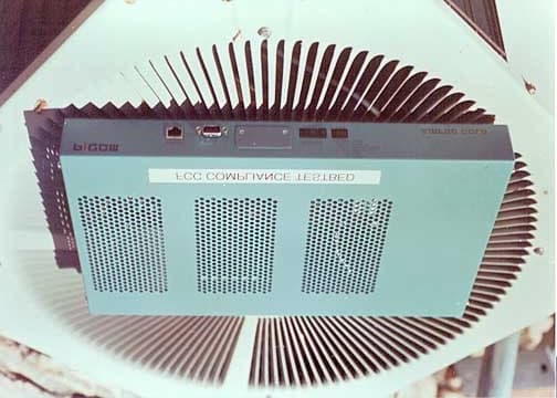
KINAPG20FNET
Mar 13, 2002Wireless LAN, AIRPRO GOLD 20F.NET
Equipment Class
DSS - Part 15 Spread Spectrum Transmitter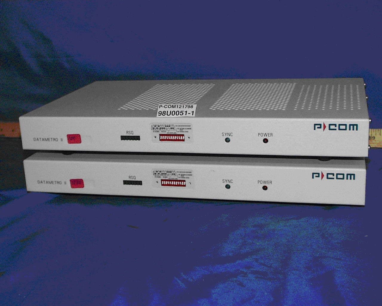
KINDM2
Mar 29, 1999Wireless Data Link
Equipment Class
DSS - Part 15 Spread Spectrum Transmitter