KJ8-0001715TORQUE MASTER i-DRIVE PRO
Wayne Dalton Corporation
Click to zoom
Application Details
- Equipment Class
- DXT - Part 15 Low Power Transceiver, Rx Verified
- Date of Grant
- Oct 24, 2007
- Application Purpose
- Original Equipment
- Date of Application
- Oct 23, 2007
- Equipment Note
- TORQUE MASTER i-DRIVE PRO
- Frequency Range
- 908.42000000 - 908.42000000
- Company
- Wayne Dalton Corporation
- Country
- United States
Documents & Files
Document Text
Text extracted from the exhibit documents filed with the FCC. Open a document above to read the original.
Users Manual
5015 B.U. Bowman Drive Buford, GA 30518 USA Voice: 770-831-8048 Fax: 770-831-8598 Certification Test Report 908.42 MHz Low Power Communication Device Transceiver 372 MHz Discrete Receiver FCC ID: KJ8-0001715 IC: 3540A-0001715 FCC Rule Part: 15.249 IC Radio Standards Specification: RSS-210 ACS Report Number: 07-0186 - 15C Manufacturer: Wayne-Dalton Corporation Model: 3790-Z Installation Guide Section1 INSTALLATION INSTRUCTIONS AND OWNER’S MANUAL Models: 3790/3790-Z/3791/3791-Z Installation Instructions and Owner’s Manual USE OF THIS MANUAL WHEN INSTALLING A NEW DOOR WITH AN IDRIVE ® : If you just fi nished installing a new garage door along with an idrive ® opener, then proceed with these instructions beginning with Step 15 on page 22. If you were referred to these instructions as part of a new door installation, then proceed with these instructions beginning with Step 1 on page 7. for TORQUEMASTER ® / TORQUEMASTER ® PLUS FPO Intergrated Z-W ave ® technology Ready for your home control net work On select models FPO IMPORTANT NOTICE! To avoid possible injury, read the enclosed instructions carefully before installing/operating this garage door opener. Pay close attention to all warnings and notes. This manual MUST be attached to the wall in close proximity to the garage door opener. Copyright 2007 Wayne-Dalton Corp. Part No. XXXXXX New 9/7/2007 GARAGE DOORS & OPENERS T o O p e r a t e D o o r Press Here 9 0 7 8 5 6 3 4 1 2 S1S2S3S4 LearnDelete Controls Package Contents Key chain/Visor Transmitter (2) Opener Deluxe Multi-function Wireless Wall Station Security Light with Diffuser Disconnect Handle Disconnect Handle Bracket “S” Hook 1/4” x 1-1/2" Hex Head Lag Screws (4) #6 x 7/8" Phillips Pan Head Screws (4) Disconnect Cable 1/4” x 2" Hex Head Lag Screws (2) Owner’s Manual Emergency Disconnect Label Installation DVD Entrapment Label 5 Button Wireless Keyless Entry #6-20 x 1/2" Phillips Pan Head Screw (1) Lock Arm Assembly Cable Clips (4) #6-32 x 3/4" Phillips Pan Head Screw (1) (For Light Fixture) 5mm x .8mm x 12mm Phillips Pan Head Screw (1) (For Lock Arm) Mounting Bracket I Please Do Not Return This Product To The Store. Call Us Directly! Our Trained Technicians Will Answer Your Questions and/or Ship Any Parts You May Need. You can reach us Toll Free at 1-888-827-3667 for Consumer Assistance or online at www.wayne-dalton.com Jumper (Optional for Safety Sensors) FPO PRE-INSTALLATION INSPECTION OF YOUR GARAGE DOOR PRIOR TO TORQUEMASTER ® IDRIVE ® INSTALLATION Congratulations, you have just purchased one of the world’s safest garage door openers! By design, this opener will detect obstructions and reverse rather than force the door through obstructions. To ensure your new idrive ® opener works as intended, your garage door must be installed and balanced properly. WHEN INSTALLING A NEW DOOR WITH AN IDRIVE ® : If you just fi nished installing a new garage door along with an idrive ® opener, then proceed with these instructions beginning with Step 15 on page 22. If you were referred to these instructions as part of a new door installation, then proceed with these instructions beginning with Step 1 on page 7. WHEN INSTALLING AN IDRIVE ® ON AN EXISTING DOOR WITH TORQUEMASTER ® OR TORQUEMASTER ® PLUS: Before installing the idrive ® opener, open and close you door manually to ensure that it operates smoothly from top to bottom. A properly balanced door should not take a lot of effort to open or close by hand. The door should stay in the open and in the closed position without drifting down or creeping up. If a door opens fast going up, the door may need spring tension reduced. If the door drops fast going down, the door may need spring tension increased. If the operation of the door does not meet these criteria, you need to adjust the spring balance per your door’s Installation Instructions and Owner’s Manual or call a professional installer to make adjustments before installing idrive ® . If the door operates properly, check and record your Torquemaster ® counterbalance spring settings (for Torquemaster Plus spring settings, see warning tag(s) attached to the end brackets or refer to your door Installation Instructions and Owner’s manual). Then proceed with unwinding of the spring(s) for installation of your idrive ® , carefully following the instructions in STEP R1 of your idrive ® Installation Instructions and Owner’s Manual. After the idrive ® is installed on the Torquemaster ® tube, rewind the Torquemaster ® or Torquemaster ® Plus to the previously recorded settings. Instruction manuals are available for download on www.wayne-dalton.com. Use the web site to also fi nd the location of your nearest professional dealer. Check out the new idrive ® installation video at www.wayne-dalton.com Idrive ® for Torquemaster ® http://www.wayne-dalton.com/idrive_TorqueMaster.asp Look for this symbol. II Please Do Not Return This Product To The Store. Call Us Directly! Our Trained Technicians Will Answer Your Questions and/or Ship Any Parts You May Need. You can reach us Toll Free at 1-888-827-3667 for Consumer Assistance or online at www.wayne-dalton.com S1S2S3S4 LearnDelete Controls Torque Tube 1” Clearance for Motor To p o f Door End Bracket Mounting Surface Electrical outlet on the wall is for opener Electrical outlet on the ceiling is for light/opener Pre-Installation Inspection A. You must have a Wayne-Dalton Torquemaster ® or Torquemaster ® Plus counterbalance system to install this opener (see A above). B. The motor requires 1" of clearance above the top of the end bracket for Torquemaster and 1-1/4” of clearance above the top of the end bracket for Torquemaster plus. C. Two electrical outlets are recommended for the idrive ® installation. One of these outlets needs to be located less than 6' from the opener. The second outlet, for the light, can be located at a position of your choice. If, in the event that an electrical outlet is not located within 6' of the opener, contact a local electrician for fu…
Text truncated - open the document above for the full version.
Users Manual
5015 B.U. Bowman Drive Buford, GA 30518 USA Voice: 770-831-8048 Fax: 770-831-8598 Certification Test Report 908.42 MHz Low Power Communication Device Transceiver 372 MHz Discrete Receiver FCC ID: KJ8-0001715 IC: 3540A-0001715 FCC Rule Part: 15.249 IC Radio Standards Specification: RSS-210 ACS Report Number: 07-0186 - 15C Manufacturer: Wayne-Dalton Corporation Model: 3790-Z Installation Guide Section2 2 Please Do Not Return This Product To The Store. Call Us Directly! Our Trained Technicians Will Answer Your Questions and/or Ship Any Parts You May Need. You can reach us Toll Free at 1-888-827-3667 for Consumer Assistance or online at www.wayne-dalton.com R3 End Bracket Removal To remove end brackets, start with the right hand end bracket and remove the lower lag screw and carriage bolt. Repeat for left hand end bracket. CAUTION: THE WINDING SHAFT MAY ROTATE WHEN REMOVING THE END BRACKET AND GEAR. Tools Needed: Power Drill 7/16” Socket Driver 1/2” Wrench Step Ladder Center Bracket & Cable Drum Removal To remove the cable drum/center bracket, follow the steps below: a. Remove the two 1/4" lag screws from the center bracket. slide center bracket to the right side of the torque tube. Lift the right side of the torque tube up and slide the cable drum and center bracket off the end of the torque tube. discard the center bracket. b. Drape the cable drum over the flagangle by the counterbalance cable and re-align the groove in the winding shaft with the round notch in the flagangle. Once aligned, lower the winding shaft and torque tube onto the flagangle. Repeat cable drum removal for left side. After completing this step, continue with Step R5 on page 5. R4 a b 1/4” Lag Screws Center Bracket Torque Tube Tools Needed: Power Drill 7/16" Socket Driver Step Ladder C a bl e D r u m N o s p a ce be t w e e n R a tch e t P a w l a n d C ab le D ru m in d ica t e s e n ga g em e n t C a b le Dr um R at c he t P a w l E NG A G E D SID E V IE W No spa c e b e tw e e n Ra tc h et P a w l a n d C ab le D r u m E N G A G E D U N D E RN E A TH V IE W Sp a c e b e tw e e n R at c he t P aw l a n d C a b l e Dr um no n -in d ic a tes e nga gem en t Ca b l e Dr u m R a tch e t P a w l D I SE N G A G E D S ID E V IEW No spa c e b e tw ee n R a tc h e t P a wl an d D IS E N G A G ED U N DER N EATH V IE W U P P ER P O S IT IO N LO W E R P O S IT IO N L O W E R P OS I TI O N S ID E V IE W U P P E R P OS I T IO N S ID E V IE W R a t c h e t P a wl in L o w e r P o s i ti on R a tc he t P a w l in U p p e r P o s it io n U se th ese I llus tra ti o n, in con j u n ct ion w ith th e I n st ruc ti o ns on th e oth er side o f th i s l abe l . WA R NIN G W A R N I N G Rac het Bra cket is un der R a c h e t B r a c k e t i s u n d e r EXTREM E SPR ING E X T R E M E S P R I N G TENSIONT E N S I O N . To avoi d possible severe or T o a v o i d p o s s i b l e s e v e r e o r fatal injury, f a t a l i n j u r y , DO NOT D O N O T re move r e m o v e fas ten ers f rom rat chet br acket f a s t e n e r s f r o m r a t c h e t b r a c k e t unt il spring(s) are f ully u n t i l s p r i n g ( s ) a r e f u l l y wnwound.w n w o u n d . To safely unw ind sp ring(s) T o s a f e l y u n w i n d s p r i n g ( s ) readr e a d and f ollow the di rection s in the a n d f o l l o w t h e d i r e c t i o n s i n t h e ins tallat ion instruct ion s/owne rs i n s t a l l a t i o n i n s t r u c t i o n s / o w n e r s man ual . m a n u a l . DO NOT REMOV E TH IS TA G. D O N O T R E M O V E T H I S T A G . 5/16” X 1-5/8” Hex Head Lag End Bracket (Right Hand) 5/16”-18 Hex Nut 5/16” - 18 X 3/4” Carriage Bolt Winding Shaft Cable Drum Groove Round Notch Flagangle Splines 3 Please Do Not Return This Product To The Store. Call Us Directly! Our Trained Technicians Will Answer Your Questions and/or Ship Any Parts You May Need. You can reach us Toll Free at 1-888-827-3667 for Consumer Assistance or online at www.wayne-dalton.com R1 Retro-Fit Installation Spring Tension Removal Counterbalance spring tension must be relieved before removing any hardware. A POWERFUL SPRING RELEASING ITS ENERGY SUDDENLY CAN CAUSE SEVERE, E VEN FATAL INJURY. NOTE: Warning tag removed for illustration clarity. Place door in the fully closed position and remove drum wraps from cable drums (if installed). Using a 7/16" wrench, loosen lock nut on the back of the end bracket. Using a power drill (high torque/gear reduced to 1300 RPM preferred), with a 7/16" socket driver, unwind the right hand winding bolt counter clockwise until the counter cover shows “0” (zero). If the door has two springs, repeat this process for the left hand side. NOTE: A door with only one spring will not have a counter assembly on the left hand side. NOTE: Spring(s) is/are fully unwound when counterbalance cables have no tension. CAUTION: DO NOT USE AN IMPACT GUN TO UNWIND THE SPRINGS! NOTE: It is recommended that cable drums and end bracket assemblies get updated to current designs for optimal performance. current end brackets are made of metal instead of plastic, and counter cover and worm gears are made of grey plastic, instead of black and white plastic. If new parts are required, contact Wayne-Dalton customer service. Tools Needed: Flat Tip Screwdriver Step Ladder R2 Right Hand Counter Removal IMPORTANT! RIGHT AND LEFT HAND IS ALWAYS DETERMINED FROM INSIDE THE GARAGE LOOKING OUT. Remove the counter cover. Slide a flat tip screwdriver between the end bracket and the counter gear. Gently pull the counter gear away from the end bracket. If the door has two springs, repeat this process for the opposite side. 7/16” Wrench Lock Nut Power Drill Counter Balance Cable Drum Wrap End Brackets (Metal) Counter Cover Worm Gear Counter Gear Flat Tip Screwdriver End Brackets (Metal) Counter Cover WARNING Winding Bolt Winding Bolt Tools Needed: 7/16" Wrench Power Drill 7/16" Socket Driver Step Ladder Cable Drum 7/16” Socket Driver Retro-Fit TorqueMaster ® RETRO-FIT TORQUEMASTER ® PLUS 4 Please Do Not Return This …
Text truncated - open the document above for the full version.
Users Manual
5015 B.U. Bowman Drive Buford, GA 30518 USA Voice: 770-831-8048 Fax: 770-831-8598 Certification Test Report 908.42 MHz Low Power Communication Device Transceiver 372 MHz Discrete Receiver FCC ID: KJ8-0001715 IC: 3540A-0001715 FCC Rule Part: 15.249 IC Radio Standards Specification: RSS-210 ACS Report Number: 07-0186 - 15C Manufacturer: Wayne-Dalton Corporation Model: 3790-Z Installation Guide Section3 11 Please Do Not Return This Product To The Store. Call Us Directly! Our Trained Technicians Will Answer Your Questions and/or Ship Any Parts You May Need. You can reach us Toll Free at 1-888-827-3667 for Consumer Assistance or online at www.wayne-dalton.com Loose Winding Shaft Cable Drum Left Hand Side Single Spring Application Groove Flagangle Torsion Tube NOTE: If you just installed the Torquemaster ® Plus counterbalance, continue with Step 5 on page 13. If you have the Torquemaster ® counterbalance system, complete Steps 2-4 on pages 11 and 12. Shake the torque tube gently to extend the winding shafts out about 5" on each side. For single spring applications, there will be no left hand spring in the torque tube. Lift the torque tube and rest it on the top of the flagangles. Orient torque tube so that back of opener is flat against header/ mounting surface. NOTE: Cable drums and torque tube are cam shaped to fit together only one way. Pre-wrap the Torquemaster ® cable drum with the counter balance cable 1/2 wrap (see illustrations). To install the cable drum, slide the cable drum over the winding shaft until the cable drum seats against the torque tube. The winding shaft must extend past the cable drum far enough to expose the splines and the groove. Align the winding shaft groove with the round notch in the flagangle. Repeat for opposite side for double spring applications. For single spring applications, insert the loose winding shaft into the left hand cable drum prior to sliding the cable drum over the torque tube. NOTE: On single spring applications, take care in handling the loose winding shaft (left side) so that it does not slide back into the torque tube. Beginning with the right hand side, lubricate entire circumference of the drive gear with lubricating oil. Slide the drive gear onto the winding shaft splines until it touches the flagangle. NOTE: On single spring applications, no drive gear is required on the left side. NOTE: If additional lubricating oil is required “Dura-Lube Engine Oil Treatment” is recommended. Cable Drum/ Drive Gear Installation Torque Tube Winding Shaft Cable Drum Counterbalance Cable Torque Tube Cable Drum Round Notch Winding Shaft Groove Winding Shaft Splines Lubricating Oil Drive Gear Flagangle Drive Gear Winding Shaft Cable Drum Cable Drum Splines Groove Flag Angle Round Notch 2 TorqueMaster ® Installation Tools Needed: Step Ladder 1/2 Wrap Shown Winding Shaft Groove align and seated in ro IDRIVE ® FOR TORQUEMASTER ® INSTALLATION 12 Please Do Not Return This Product To The Store. Call Us Directly! Our Trained Technicians Will Answer Your Questions and/or Ship Any Parts You May Need. You can reach us Toll Free at 1-888-827-3667 for Consumer Assistance or online at www.wayne-dalton.com Tools Needed: Step Ladder End Bracket Installation Counter Installation IMPORTANT! WARNING TAGS MUST BE SECURELY ATTACHED TO BOTH END BRACKETS. Slide the right hand end bracket over the drive gear. Replace #10 phillips head screw that was removed in Step R3. Secure end bracket and the flagangle to the jamb using (2) 5/16” x 1-5/8" lag screws. NOTE: Older end brackets may not have a hole needed for the opener’s emergency disconnect cable. If the right hand end bracket does not have a hole for the disconnect cable, drill a 3/32" (3mm) hole as shown prior to installing the end bracket. Install the right side counter gear, with the missing tooth toward the outside and away from the end bracket. Press the counter gear onto the end bracket until snaps engage. Select the right hand counter cover and align the hex of the counter cam with the end of the winding shaft. Also, align the “0” on the counter cover with the raised rib on the end bracket. Press the counter cover against the counter gear until it locks into place. Repeat for left hand side for double spring applications. NOTE: No drive gear, counter gear or counter cover is required on left hand side for single spring applications. Only an end bracket is needed. IMPORTANT! AT THIS TIME DO NOT WIND COUNTERBALANCE SPRINGS! After completing this step, continue with Step 5 on page 13. Winding Shaft Inside End Bracket Missing Tooth Raised Rib Hex of the Counter Cam Counter Cover 3/32” Hole 5/16 x 1-5/8” Lag Screws Counter Gear #10 Phillips Head Screw Warning Ta g 1/4” 1/8” Tools Needed: Power Drill 3/32” Drill Bit 7/16” Socket Driver Phillips Head Screwdriver Step Ladder End Bracket Flagangle 3 4 13 Please Do Not Return This Product To The Store. Call Us Directly! Our Trained Technicians Will Answer Your Questions and/or Ship Any Parts You May Need. You can reach us Toll Free at 1-888-827-3667 for Consumer Assistance or online at www.wayne-dalton.com S1 S2 S3 S4 LearnDelete Controls S1 S2 S3 S4 LearnDelete Controls Positioning Support Bracket NOTE: idrive ® must be installed on a solid mounting surface. Locate the mounting surface. The mounting surface is a vertical board running directly above the center of the door. Remove (2) 1/4”-20 flange nuts from bottom of opener. NOTE: Do not discard flange nuts. Place the support bracket underneath opener, to the right side of motor, centered on mounting surface. Using a tape measure, maintain equal measurements between torque tube and top of door at both ends and in center to ensure torque tube is level. Once torque tube is level, with idrive resting on support bracket, drill 1/8” pilot holes for the lag screws. Now secure support bracket to the mounting surface with (2) 1/4” x 1-1/2" lag screws. NOTE: If wood mounting surface is covered with dry wall, use 1/4” x 2” lag screws. 1/4 x …
Text truncated - open the document above for the full version.
Users Manual
5015 B.U. Bowman Drive Buford, GA 30518 USA Voice: 770-831-8048 Fax: 770-831-8598 Certification Test Report 908.42 MHz Low Power Communication Device Transceiver 372 MHz Discrete Receiver FCC ID: KJ8-0001715 IC: 3540A-0001715 FCC Rule Part: 15.249 IC Radio Standards Specification: RSS-210 ACS Report Number: 07-0186 - 15C Manufacturer: Wayne-Dalton Corporation Model: 3790-Z Installation Guide Section4 27 Please Do Not Return This Product To The Store. Call Us Directly! Our Trained Technicians Will Answer Your Questions and/or Ship Any Parts You May Need. You can reach us Toll Free at 1-888-827-3667 for Consumer Assistance or online at www.wayne-dalton.com P E 1 2 S 1 S2 S3 S 4 Lear n D Controls Wire Routing 21 Uncoil wires from photoelectric sensors and route wires up garage wall and along door header towards the right side of the opener. Route wires behind torque tube and tack wires in place with insulated staples (not supplied).Take care to run wires in a location where they will not interfere with the operation of the door. Do Not Staple Through Wire. NOTE: If wires must be lengthened or spliced use wire nuts or suitable connectors. NOTE: Take care to run wires in a location where they will not interfere with the operation of the door and do not staple through wire. Connect photoelectric sensors to the opener terminal block on right side of the opener. Sepa- rate wire ends and strip about 1/2” of insulation off each of the wire ends. Insert a 3/32” (2.5mm) max. width fl atblade screwdriver into the lower hole #1 of the terminal block. Twist screwdriver to open wire clamp in upper hole #1 of terminal block. Insert both sender and receiver solid white wires into upper hole #1 until the wires bottom out and release screwdriver tension. Insert and twist screwdriver in lower hole #2 and insert both sender and receiver wires (white with black stripe) into upper hole #2 until wires bottom out and release screwdriver tension. Be sure to observe polarity. Once wires are connected, install jumper through the front opener cover on to the pins labeled PE. IMPORTANT! KEEP SENDER/RECEIVER WIRES AWAY FROM MOVING COMPONENTS. Lightly pull on external wires to test for secure connection. Check that the wires are stapled in place and staples have not cut wire insulation. Insert screw driver into lower hole #1 Insert wires into upper hole #2 Insert wires into upper hole #1 Insert screw driver into lower hole #2 White wires with black stripe Solid white wires RIGHT HAND SIDE VIEW OF OPENER Jumper installed Jumper Pins labeled “PE” VIEW OF THE OPENER FROM THE FRONT Tools Needed: Flat Tip Screwdriver Pliers/Wire Cutters Sensor Wire Installation (Required on 8000 Series Doors) PRE-OPERATION 28 Please Do Not Return This Product To The Store. Call Us Directly! Our Trained Technicians Will Answer Your Questions and/or Ship Any Parts You May Need. You can reach us Toll Free at 1-888-827-3667 for Consumer Assistance or online at www.wayne-dalton.com S1 S2 S3 S4 Learn Delete Controls With the emergency disconnect still in the manual door operated position, manually raise the door to the fully open position. Then, manually lower the door to the fully closed position verifying freedom of movement and good door balance. Tighten both 1/4”-20 flange nuts, securing the opener to the support bracket. NOTE: Good door balance and freedom of movement are essential for proper opener performance. If door is heavy to lift, hard to close or if door sticks or binds in the track, make proper adjustments now. Securing the Opener and Checking for Obstructions Align the safety sensors by moving the sending and receiving units in or out until the alignment light on the receiving unit comes on. The 1/4”-20 carriage bolt can be loosened to move the safety sensor in or out, as required. If you have difficulty aligning the beams, check that both mounting brackets are mounted at the same height and remount if necessary. Additional minor adjustments can be made by slightly bending the mounting brackets. Once the alignment light comes on, tighten all bolts and mounting screws. Finish securing all wires making sure not to break or open any of the conductors. Loop and secure any excess wire. Safety Sensor Alignment 1/4”-20 Carriage Bolts In Out In Out Top View Top View For this adjustment, bend Bracket at wall mount 1/4” - 20 Flange Nuts Support Bracket Tools Needed: Pliers 22 23 Tools Needed: 7/16” Wrench Step Ladder 29 Please Do Not Return This Product To The Store. Call Us Directly! Our Trained Technicians Will Answer Your Questions and/or Ship Any Parts You May Need. You can reach us Toll Free at 1-888-827-3667 for Consumer Assistance or online at www.wayne-dalton.com T o O p e r a t e D o o r Pres s Here TO AVOID INJURY, NO ONE SHOULD CROSS THE PATH OF A MOVING DOOR! The profile routine automatically sets the door open and close limits and calibrates obstruction sensing. During the profile routine, the door will move up and down twice. NOTE: If an object such as a ceiling beam obstructs the door from opening completely, skip this step. Set a Custom Upper Limit, see Step 26. NOTE: The door must be in its fully closed position and the disconnect handle must be in the motor operated position (upper position) to initiate the profile routine. NOTE: Profile routine will not run if safety sensors are not aligned (only if required installation). Press and hold the profile button for five (5) seconds. The opener will beep twice, release the profile button, indicating the activation of the profile routine. The door will now move to the fully open position and stop, beep twice and then the door will close completely. Next, the door will go through one more up/ down cycle. Once this is complete, the door limits are set and the profile is complete. NOTE: Upon successful completion proceed to Step 27. Profile Routine (Standard Upper Limit) Programming Light Fixture Program Button Light Button Profile Button Tools Needed: None LED WARNING Press the red …
Text truncated - open the document above for the full version.
Cover Letter(s)
Garage Door Systems Wayne-Dalton Corp. • One Door Drive • Mt. Hope, Ohio 44660 • 330-763-8000 • FAX 330-763-8032 ____________________________________________________________________________________ CONFIDENTIALITY REQUEST September 28, 2007 Federal Communications Commission Equipment Authorization Branch 7435 Oakland Mills Road Columbia, MD. 21046 Gentlemen: Wayne-Dalton Corp. respectfully requests confidentiality of certain materials provided with the submission of the Torque Master i-Drive Pro under FCC ID: KJ8-0001715 in accordance with FCC Regulations 0.459. The confidentiality request applies to the 1) Schematic, 2) Bill of Materials, 3) Detailed Operational Description and, 4) Detailed Block Diagram contained in this filing and exhibits listed below. 07-0186 – Schematics.pdf 07-0186 – Parts List.pdf 07-0186 – Theory of Operation.pdf 07-0186 – System Block Diagram.pdf The Torque Master Pro i-Drive has been developed at considerable effort and expense by Wayne- Dalton Corp. These items are considered as Trade Secrets and, therefore, public access to the proprietary material could possibly result in duplication of equipment that could severely damage the company’s business advantage. I appreciate your assistance in this manner. Sincerely, David Ayer RF Design Engineer – N6WJD
External Photos
5015 B.U. Bowman Drive Buford, GA 30518 USA Voice: 770-831-8048 Fax: 770-831-8598 Certification Test Report 908.42 MHz Low Power Communication Device Transceiver 372 MHz Discrete Receiver FCC ID: KJ8-0001715 IC: 3540A-0001715 FCC Rule Part: 15.249 IC Radio Standards Specification: RSS-210 ACS Report Number: 07-0186 - 15C Manufacturer: Wayne-Dalton Corporation Model: 3790-Z External Photographs Model: 3790-Z FCC ID: KJ8-0001715 IC: 3540A-0001715 5015 B.U. Bowman Drive Buford, GA 30518 USA Voice: 770-831-8048 Fax: 770-831-8598 Figure 1: External – Front View Model: 3790-Z FCC ID: KJ8-0001715 IC: 3540A-0001715 5015 B.U. Bowman Drive Buford, GA 30518 USA Voice: 770-831-8048 Fax: 770-831-8598 Figure 2: External – Side View Model: 3790-Z FCC ID: KJ8-0001715 IC: 3540A-0001715 5015 B.U. Bowman Drive Buford, GA 30518 USA Voice: 770-831-8048 Fax: 770-831-8598 Figure 3: External – Side View Model: 3790-Z FCC ID: KJ8-0001715 IC: 3540A-0001715 5015 B.U. Bowman Drive Buford, GA 30518 USA Voice: 770-831-8048 Fax: 770-831-8598 Figure 4: External – Bottom View Model: 3790-Z FCC ID: KJ8-0001715 IC: 3540A-0001715 5015 B.U. Bowman Drive Buford, GA 30518 USA Voice: 770-831-8048 Fax: 770-831-8598 Figure 5: External – Back View Model: 3790-Z FCC ID: KJ8-0001715 IC: 3540A-0001715 5015 B.U. Bowman Drive Buford, GA 30518 USA Voice: 770-831-8048 Fax: 770-831-8598 Figure 6: External – Top View
ID Label/Location Info
5015 B.U. Bowman Drive Buford, GA 30518 USA Voice: 770-831-8048 Fax: 770-831-8598 Certification Test Report 908.42 MHz Low Power Communication Device Transceiver 372 MHz Discrete Receiver FCC ID: KJ8-0001715 IC: 3540A-0001715 FCC Rule Part: 15.249 IC Radio Standards Specification: RSS-210 ACS Report Number: 07-0186 - 15C Manufacturer: Wayne-Dalton Corporation Model: 3790-Z Labeling Information 2.25 1.62 NOTES: 1. LABELS MUST BE PROVIDED ON ROLLS. 2. MATERIAL: FLEXMARK LABEL STOCK MM-200-S, L-23 WITH BRIGHT SILVER BACKING, BLACK LETTERS, .001 CLEAR MYLAR OVERLAY. ZONEREVDESCRIPTIONDATEAPPROVED 12 B B A 1 A 2 PROJECTION CHARACTERISTICS ANGLE KEY CONTROL INTERPRET DIMENSIONS AND TOLERANCES PER ASME Y14.5 UNLESS OTHERWISE SPECIFIED DIMENSIONS ARE IN INCHES TOLERANCES ARE TITLE SCALE PART NUMBER RELEASE DRAWING NUMBER SHEET REVISION SIZE STATUS PROJECT DRAWN BY DATE CHECKED BY DATE DATE APPROVED BY WEIGHT (LB) MATERIAL FINISH OF WAYNE-DALTON CORP ONE DOOR DRIVE MT HOPE, OH 44660 (330) 674-7015 A. JONES D. KYLE D. KYLE 8/17/07 8/17/07 9/21/07 OPERATOR 40 XR PENDING PCR#:W-1455A 1 1 A 2:1 334098 334098 P00 DO NOT SCALE DRAWING .015 .010 .0005 LINEAR .X LINEAR .XX LINEAR .XXX LINEAR .XXXX ANGULAR .50 .005 THIS DRAWING IS THE PROPERTY OF WAYNE- DALTON AND IS LOANED WITH THE EXPRESSED AGREEMENT THAT THE DRAWINGS AND INFORMATION THEREIN CONTAINED ARE THE PROPERTY OF WAYNE-DALTON AND WILL NOT BE REPRODUCED, COPIED, OR OTHERWISE DISPOSED OF, DIRECTLY OR INDIRECTLY, AND WILL NOT BE USED IN WHOLE OR IN PART TO ASSIST IN MAKING OR TO FURNISH ANY INFORMATION FOR THE MAKING OF DRAWINGS, PRINTS, OR OTHER REPRODUCTION THEREOF, OR FOR THE MAKING OF APPARATUS OR PARTS THEREOF, EXCEPT UPON WRITTEN PERMISSION OF WAYNE-DALTON FIRST OBTAINED AND SPECIFIC AS TO EACH CASE. THE ACCEPTANCE OF THIS DRAWING WILL BE CONSTRUED AS AN ACCEPTANCE OF THE FOREGOING AGREEMENT. R LABEL, DATA, UL/FCC, TM, PRO 3790-Z SEE NOTES SEE NOTES idrive Pro Z-Wave Data label placement location (item number 10)
Internal Photos
5015 B.U. Bowman Drive Buford, GA 30518 USA Voice: 770-831-8048 Fax: 770-831-8598 Certification Test Report 908.42 MHz Low Power Communication Device Transceiver 372 MHz Discrete Receiver FCC ID: KJ8-0001715 IC: 3540A-0001715 FCC Rule Part: 15.249 IC Radio Standards Specification: RSS-210 ACS Report Number: 07-0186 - 15C Manufacturer: Wayne-Dalton Corporation Model: 3790-Z Internal Photographs Model: 3790-Z FCC ID: KJ8-0001715 IC: 3540A-0001715 5015 B.U. Bowman Drive Buford, GA 30518 USA Voice: 770-831-8048 Fax: 770-831-8598 Figure 1: 908.42MHz Transceiver / 372MHz Receiver Board - Front Model: 3790-Z FCC ID: KJ8-0001715 IC: 3540A-0001715 5015 B.U. Bowman Drive Buford, GA 30518 USA Voice: 770-831-8048 Fax: 770-831-8598 Figure 2: 908.42MHz Transceiver / 372MHz Receiver Board - Back Model: 3790-Z FCC ID: KJ8-0001715 IC: 3540A-0001715 5015 B.U. Bowman Drive Buford, GA 30518 USA Voice: 770-831-8048 Fax: 770-831-8598 Figure 3: 908.42MHz Transceiver / 372MHz Receiver Board Model: 3790-Z FCC ID: KJ8-0001715 IC: 3540A-0001715 5015 B.U. Bowman Drive Buford, GA 30518 USA Voice: 770-831-8048 Fax: 770-831-8598 Figure 4: Transceiver / Receiver PCB mounted on Main PCB Model: 3790-Z FCC ID: KJ8-0001715 IC: 3540A-0001715 5015 B.U. Bowman Drive Buford, GA 30518 USA Voice: 770-831-8048 Fax: 770-831-8598 Figure 5: Main…
Text truncated - open the document above for the full version.
Contact Information
Applicant
Richard L. BARDIN(Electrical Engineer)
Test Firm
Advanced Compliance Solutions, Inc.Douglas Massey
Technical Specifications
| # | Rule Parts | Frequency Range | Power Output |
|---|---|---|---|
| 1 | 15C | 908.42 MHz - 908.42 MHz | - |
Other Applications from Wayne Dalton Corporation

KJ8-0001142
Mar 22, 2007Z-WAVE PRODRIVE
Equipment Class
DXX - Part 15 Low Power Communication Device Transmitter
KJ8-0001115A
Mar 13, 2007Z-Wave X-10 Bridge
Equipment Class
DXT - Part 15 Low Power Transceiver, Rx Verified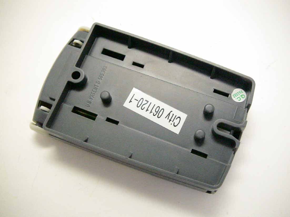
KJ80001071A
Jan 16, 2007Wireless Remote Control
Equipment Class
DSC - Part 15 Security/Remote Control Transmitter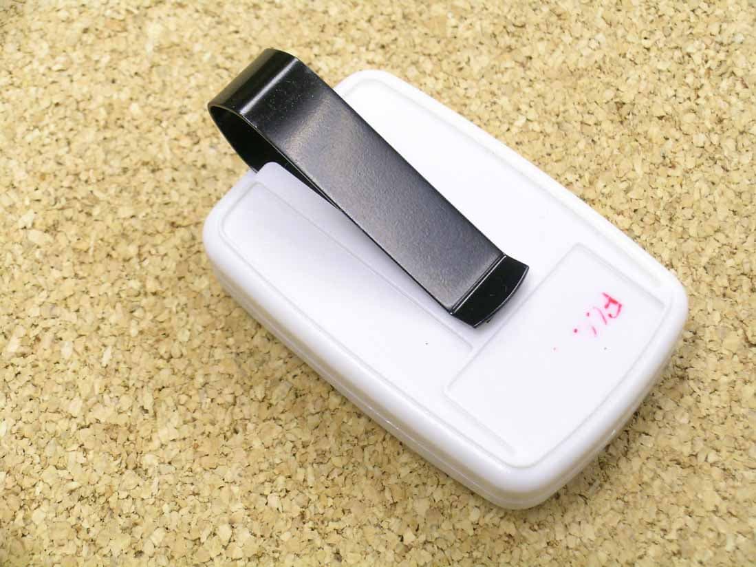
KJ80000593
Jan 16, 2007Wireless Keychain Remote Control
Equipment Class
DSC - Part 15 Security/Remote Control Transmitter
KJ8KYE5-3720C
Sep 18, 2006Wireless Keyless Entry Control
Equipment Class
DSC - Part 15 Security/Remote Control Transmitter