KJ8KYE-372CSWWIRELESS KEYLESS ENTRY SYSTEM
Wayne Dalton Corporation
Click to zoom
Application Details
- Equipment Class
- DSC - Part 15 Security/Remote Control Transmitter
- Date of Grant
- Jul 24, 2006
- Application Purpose
- Original Equipment
- Date of Application
- Jul 24, 2006
- Equipment Note
- WIRELESS KEYLESS ENTRY SYSTEM
- Frequency Range
- 372.00000000 - 372.00000000
- Company
- Wayne Dalton Corporation
- Country
- United States
Documents & Files
Document Text
Text extracted from the exhibit documents filed with the FCC. Open a document above to read the original.
Users Manual
Locate Keyless Entry Unit: within sight of door, at a minimum height of 5 feet so it cannot be reached by small children, and away from all moving parts of the door. Choose a convenient location that does not interfere with the normal opening and closing operation of the door, such as the door jamb. CAUTION: The keypad should be mounted a minimum of 5 feet from the floor to keep it out of the reach of small children.Two screws are included for proper mounting into wood or other similar material. If you're mounting into some other material, consult a building contractor to insure proper hardware is used for a secure mounting. Drilling Template For Keyless Entry Leave screw head exposed1/8" from wall. Once you have determined the mounting location, use the drilling template to determine hole positions and drill a 5/64" pilot hole 3/4" deep for the two mounting screws. Insert screw into the upper pilot hole leaving the head of the screw exposed about 1/8" from the wall. Slide and lock the back keyhole slot over the exposed screw and position the unit vertically. Remove battery door and battery. Insert the lower screw and tighten. Replace battery and battery door. The following explains how your Keyless Entry can be used to OPEN, CLOSE, START, and STOP your door. Activate your keypad by pressing the ON/RESET button; keypad will illuminate.Enter your 4-digit PIN (personal identification number); keypad will rapidly blink for 2 seconds and then change to a slow blink; door will begin to move. 1. 2.NOTE: If you inadvertently enter an incorrect code, the keypad will still blink but door will not open. Reset with the ON/RESET button and reenter your PIN number. Unit remains active for next 15 sec. Pressing any key, except the ON/RESET, will stop the door if opening, or reverse the door if closing. Pressing the ON/RESET button while keypad is slow blinking will turn off the unit. Pressing ON/RESET again will reset the unit so that the PIN can be entered again. 3.4. Your new Model KEP2-0000 Wireless Keyless Entry contains a state-of-the-art wireless digital transmitter capable of operating an unlimited number of compatible garage door openers. For added security, your Wireless Keyless Entry utilizes a "rolling code" technology that, each time the transmitter communicates with the receiver, sets a new code, selecting from millions of combinations, reducing the possibility of electronic equipment causing unwanted access. For proper operation it is important that you follow the programming directions and sequence as written. Under normal operating conditions, the battery should be changed once every 12 months. Dispose of used batteries properly. To replace battery perform the following steps:A. Raise Keyless Entry Cover to expose battery door.B. Snap open door with a coin and remove old battery.C. Replace battery (12 volt MN 21) with positive terminal to right and snap close battery door. Battery Door Pre-drill a 5/64 pilot hole 3/4" deep Pre-drill a 5/64 pilot hole 3/4" deep Wayne Dalton Corp. One Door Drive n Mt. Hope, OH 44660 800-305-4349 n Fax 800-884-5065 Mounting Model KEP2-0000 Wireless Keyless Entry System How Your Keyless Entry Operates Your Opener Battery Replacement P/N 288832 NOTE: This equipment has been tested and found to comply with the limits for a Class B digital device, pursuant to Part 15 of the FCC Rules. These limits are designed to provide reasonable protection against harmful interference when the equipment is operated in a residential environment. This equipment generates, uses, and can radiate radio frequency energy and, if not installed and used in accordance with the instruction manual, may cause harmful interference to radio communications. However, there is no guarantee that interference will not occur in a particular installation. If this equipment does cause harmful interference to radio or television reception, which can be determined by turning the equipment off and on, the user is encouraged to try to correct the interference by one or more of the following measures:- Reorient or relocate the receiving antenna.- Increase the separation between the equipment and receiver. - Connect the equipment into an outlet on a circuit different from that to which the receiver is connected.- Consult the dealer or an experienced radio/TV technician for help. PLEASE READ ALL INSTRUCTIONS THOROUGHLY TO FAMILIARIZE YOURSELF WITH THE PROGRAMMING PROCEDURE BEFORE BEGINNING. SAVE THESE INSTRUCTIONS FOR REFERENCE WHENEVER YOU WISH TO CHANGE YOUR PERSONAL IDENTIFICATION NUMBER (PIN) Before your Wireless Keypad will be able to operate the opener, there are several programming steps that have to be completed. FCC WARNING To comply with FCC rules, adjustment or modification of transmitter is prohibited. THERE ARE NO USER SERVICEABLE PARTS EXCEPT FOR BATTERY REPLACEMENT. Always keep moving door in sight and away from people and objects until it is completely closed. NO ONE SHOULD CROSS THE PATH OF THE MOVING DOOR.Never let children operate or play with door controls. Keep all controls away from children. WARNING Programming or Changing Personal Identification Number A. It is recommended that the keyless entry be programmed before mounting to wall.B . Place the garage door in the down position. C. Press the transmitter program button on the garage door opener to switch the opener to the transmitter learn mode. depending on the model of opener, LED on opener will light or audible signal will beep one time indicating the opener is in the transmitter learn mode.D. Push the ON/RESET button of the keyless entry. Keypad will light indicating the unit has been activated and is waiting for commands. E. Press the desired four digit PIN number, then hold the "0" key for several seconds (ex. 1-2-3-4-0). Garage door will move up 6" to acknowledge acceptance of the keyless entry. Continue holding the "0" key until the door begins to move back down. Door will return to the down position and stop.NOTE: If th…
Text truncated - open the document above for the full version.
Cover Letter(s)
Wayne-Dalton Corp. • Ellyson Industrial Park • 3395 Addison Drive • Pensacola, FL 32514 • 850-474-9890 • FAX 850-474-1254 Federal Communications Commission Authorization and Evaluation Division Confidentiality Request regarding application for certification of FCC ID: KJ8KYE- 372CSW. Pursuant to Sections 0.457 and 0.459 of the Commission’s Rules, we hereby request confidential treatment of information accompanying this application as outlined below: 1) Schematics accompanying filing for WDC Model # KEP2-0001, FCC ID: KJ8KYE-372CSW 2) Block Diagrams accompanying filing for WDC Model # KEP2-0001 FCC ID: KJ8KYE-372CSW 3) Circuit descriptions accompanying filing for WDC Model # KEP2-0001 FCC ID: KJ8KYE-372CSW The above materials contain trade secrets and proprietary information not customarily released to the public. The public disclosure of these materials may be harmful to the applicant and provide unjustified benefits to its competitors. The applicant understands that pursuant to Section 0.457 of the Rules, disclosure of this application and all accompanying documentation will not be made before the date of the Grant for this application. Sincerely, Richard Bardin, Electrical Engineer (850) 475-6004 [email protected]
ID Label/Location Info
Proposed FCC ID Label Location
ID Label/Location Info
INFORMATION IN THIS DRAWING AND ORAL INFORMATION REGARDING THIS PART OR THE SYSTEM IN WHICH IT IS USED IS CONSIDERED CONFIDENTIAL TO THE WAYNE DALTON CORP. THIS PRINT IS ONLY TO BE USED FOR THE PURPOSES OF QUOTATION AND ANY DISCUSSION OF FUNCTION OF THE PART OR THE SYSTEM IN WHICH THIS PART IS USED IS TO BE WITHIN THE INTERNAL COMMUNICATIONS OF THE QUOTING COMPANY AND WAYNE DALTON CORP. WEIGHTSCALE SHEETOF 1 REVCAGE CODESIZEDRAWING NUMBER R TITLE (678) 417-0115 4400 River Green Parkway, Suite 220B Duluth, GA 30096 DATE DATE DATE A ANGLE PROJECT DRAWN BY CHK. APPR. MATERIAL: FINISH: INTERPRET DIMENSIONS AND TOLERANCES PER ASME Y14.5M-1995 LIMITS UNLESS OTHERWISE NOTED: APPLICATION USED ONNEXT ASSY 1:1 ASSEMBLY TOL.1 TOL.01 TOL.005 ANGLE LBS. PROJECTION TOL .X TOL .XX TOL .XXX ANGLE B A 1 A B 23 123 Scale 1:1 KEP2 PRODUCT LABEL 0000804 1 J. HUGHES06-23-06 KEP2 A J. HUGHES06-23-06 J. HUGHES06-23-06 LABEL ARTWORK NOTES: 1. FONTS AND PLACEMENT OF GRAPHICS AND TEXT ARE TO BE TAKEN FROM ARTWORK. GRAPHICS SHOWN ARE REPRESENTATIVE ONLY. ARTWORK FILE AVAILABLE FROM WAYNE-DALTON CORP. 2. MATERIAL TO BE 4 MIL WHITE VINYL Flexcon V400 FW, V98 ADHESIVE OR EQUIVALENT. 3. PRINTED SIDE SHOWN, ADHESIVE ON OPPOSITE SIDE. 4. TEXT TO BE BLACK ON WHITE MATERIAL. WAYNE-DALTON CORP. Keyless Entry Model KEP2 0000804 This device complies with Part 15 of the FCC rules. Operation is subject to the following two conditions: (1) this device may not cause harmful interference, and (2) this device must accept any interference received, including interference that may cause undesired operation. IC: 3540A-KYE2C372 This Class B digital apparatus complies with Canadian ICES-003. Cet appareil numérique de la classe B est conforme à la norme NMB-003 du Canada. FCC ID: KJ8KYE-372CSW DATE: 2.250" 1.500" WAYNE-DALTON CORP. Keyless Entry Model KEP2 0000804 This device complies with Part 15 of the FCC rules. Operation is subject to the following two conditions: (1) this device may not cause harmful interference, and (2) this device must accept any interference received, including interference that may cause undesired operation. IC: 3540A-KYE2C372 This Class B digital apparatus complies with Canadian ICES-003. Cet appareil numérique de la classe B est conforme à la norme NMB-003 du Canada. FCC ID: KJ8KYE-372CSW DATE:
Test Report
3395 ADDISON DR. PENSACOLA, FL 32514 UNITED STATES OF AMERICA Wayne-Dalton Corp. • Ellyson Industrial Park • 3395 Addison Drive • Pensacola, FL 32514 • 850-474-9890 • FAX 850-475-6036 Date: July 24, 2006 Timco Engineering, Inc. 849 NW State Road 45 P.O. Box 370 Newberry, Florida 32669 Re.: Duty Cycle Analysis for Wayne-Dalton Corp. Model: KEP2-0001 FCC ID: KJ8KYE-372CSW IC: 3540A-KYE2C372 To Whom It May Concern: Wayne-Dalton Corp., assures that the below analysis of transmission duty-cycle is accurate and complete. Duty-cycle correction factor, per FCC Part 15, is based on a duty-cycle window of 100mS containing the “worst case”, highest duty-cycle, for the transmission under consideration. Since the message repetition rate of the KEP2 is 10 Hz (The message repeats every 100 mS) the analysis is quite straight forward. For the device in question the nominal timing element (TE) is 200uS; the transmission of a message consists of 12 preamble pulses each 1 TE in length with one TE of no transmission between them; followed by 2mS of no transmission; followed by 66 data bits, each 3 TE in length; followed by 1 TE no transmission and a stop bit 1 TE in length. 3395 ADDISON DR. PENSACOLA, FL 32514 UNITED STATES OF AMERICA Wayne-Dalton Corp. • Ellyson Industrial Park • 3395 Addison Drive • Pensacola, FL 32514 • 850-474-9890 • FAX 850-475-6036 The worst case data would be all ‘0’s transmitted, that is 2 of the three TEs having RF energy transmitted. Therefore the worst case transmission time in a 100 mS window is: (12*200 uS) + (2*66*200 uS) + (1*200 uS) = 29,000 uS or 29%; for a duty-cycle correction factor of 20*log (.29) = -10.75 dB. The device employs a 50ppm crystal for timing in the MCU and therefore the timing will not vary by more than .005% or 5 uS over an entire message. Sincerely, Richard Bardin, Electrical Engineer (850) 475-6004 [email protected]
Test Report
FCC PART 15.231 LOW POWER TRANSMITTER TEST REPORT APPLICANT Wayne-Dalton Corp. 3395 Addison Drive Pensacola, Fl 32514 USA FCC ID KJ8KYE-372CSW MODEL NUMBER KEP2 PRODUCT DESCRIPTION Keyless Transmitter DATE SAMPLE RECEIVED June 1, 2006 DATE TESTED June 1, 2006 TESTED BY Mario R. De Aranzeta APPROVED BY Frank DeNuzzo TIMCO REPORT NO. 1135AUT6TestReport TOTAL PAGES 12 TEST RESULTS Pass Fail THE ATTACHED REPORT SHALL NOT BE REPRODUCED EXCEPT IN FULL WITHOUT THE WRITTEN APPROVAL OF TIMCO ENGINEERING, INC. 849 NW STATE ROAD 45 NEWBERRY, FL 32669 USA PH: 888.472.2424 OR 352.472.5500 FAX: 352.472.2030 EMAIL: [email protected] HTTP: //WWW.TIMCOENGR.COM Certificate # 0955-01 Certificate # 0955-01 APPLICANT: WAYNE-WALTON CORP. FCC ID: KJ8KYE-372CSW REPORT: V:\W\W-Dalton_KJ8\1135AUT6\1135AUT6TestReport.doc Page 2 of 10 TABLE OF CONTENTS STATEMENT OF COMPLIANCE.................................................................................. 3 GENERAL INFORMATION .......................................................................................... 4 EMC EQUIPMENT LIST ............................................................................................. 5 TEST PROCEDURE ................................................................................................... 6 RADIATION INTERFERENCE ..................................................................................... 7 CALCULATION OF DUTY CYCLE ............................................................................... 9 OCCUPIED BANDWIDTH ......................................................................................... 10 Certificate # 0955-01 APPLICANT: WAYNE-WALTON CORP. FCC ID: KJ8KYE-372CSW REPORT: V:\W\W-Dalton_KJ8\1135AUT6\1135AUT6TestReport.doc Page 3 of 10 STATEMENT OF COMPLIANCE This equipment has been tested in accordance with the standards identified in the referenced test report. To the best of my knowledge and belief, these tests were performed using the measurement procedures described in this report and demonstrate that the equipment complies with the appropriate standards. No modifications were made to the equipment during testing in order to demonstrate compliance with these standards. I attest that the necessary measurements were made by me or under my supervision, at Timco Engineering, Inc. located at 849 N.W. State Road 45, Newberry, Florida 32669 USA. Authorized by: Mario de Aranzeta Signature: Function: Engineer Date: June 1, 2006 Tested by: Mario de Aranzeta Signature: on file Date: June 1, 2006 Certificate # 0955-01 APPLICANT: WAYNE-WALTON CORP. FCC ID: KJ8KYE-372CSW REPORT: V:\W\W-Dalton_KJ8\1135AUT6\1135AUT6TestReport.doc Page 4 of 10 GENERAL INFORMATION DUT Specification The test results relate only to the items tested. DUT Description Keyless Transmitter FCC ID KJ8KYE-372CSW Model Number KEP2 Serial Number N/A Operating Frequency 372 MHz No. of Channels N/A Type of Emission N/A Modulation FM 110–120Vac/50– 60Hz DC Power DUT Power Source Battery Operated Exclusively Test Item Prototype Pre-Production Production Type of Equipment Fixed Mobile Portable Antenna N/A Antenna Connector N/A Test Facility: The test sites used by Timco Engineering Inc. for collecting radiated and conducted emission data are located at 849 NW State Road 45 Newberry, FL 32669 USA. Test Condition: The DUT was tested in the laboratory in an environment with normal temperature and humidity. The temperature was 26ºC with a relative humidity of 50%. Modification to the DUT: No modification was made to the DUT during testing. Test Exercise (e.g software description, test signal, etc.): The DUT was placed in continuous transmit mode of operation. Applicable Standards: ANSI C63.4: 2003 FCC CFR 47 Part 15.231 Certificate # 0955-01 APPLICANT: WAYNE-WALTON CORP. FCC ID: KJ8KYE-372CSW REPORT: V:\W\W-Dalton_KJ8\1135AUT6\1135AUT6TestReport.doc Page 5 of 10 EMC EQUIPMENT LIST Device Manufa cturer Model Serial Number Cal/Char Date Due Date 3-Meter OATS TEI N/A N/A Listed 1/11/06 1/10/09 3/10-Meter OATS TEI N/A N/A Listed 3/27/04 3/26/07 Analyzer Tan Tower Spectrum Analyzer HP 8566B Opt 462 3138A07786 3144A20661 CAL 12/7/05 12/7/07 Analyzer Tan Tower RF Preselector HP 85685A 3221A01400 CAL 12/7/05 12/7/07 Analyzer Tan Tower Quasi-Peak Adapter HP 85650A 3303A01690 CAL 12/8/05 12/8/07 Analyzer Tan Tower Preamplifier HP 8449B-H02 3008A00372 CAL 12/8/05 12/8/07 Analyzer Blue Tower Spectrum Analyzer HP 8568B 2928A04729 2848A18049 CAL 4/13/05 4/13/07 Analyzer Blue Tower RF Preselector HP 85685A 2926A00983 CAL 9/5/05 9/5/07 Analyzer Blue Tower Quasi-Peak Adapter HP 85650A 2811A01279 CAL 4/13/05 4/13/07 Analyzer Silver Tower Spectrum Analyzer HP 8566B Opt 462 3552A22064 3638A08608 CAL 12/8/04 12/8/06 Analyzer Silver Tower RF Preselector HP 85685A 2620A00294 CAL 4/27/04 12/8/06 Analyzer Silver Tower Quasi-Peak Adapter HP 85650A 3303A01844 CAL 12/8/04 12/8/06 Analyzer Open- Frame Tower Preamplifier HP 8449B 3008A01075 CAL 8/8/05 8/8/07 Antenna: Biconnical Electro- Metrics BIA-25 1171 CAL 4/29/05 4/29/07 Antenna: Biconnical Eaton 94455-1 1096 CAL 8/17/04 8/17/06 Antenna: Biconnical Eaton 94455-1 1057 CAL 12/12/05 12/12/07 Antenna: Log- Periodic Electro- Metrics LPA-25 1122 CAL 8/26/04 8/26/06 Certificate # 0955-01 APPLICANT: WAYNE-WALTON CORP. FCC ID: KJ8KYE-372CSW REPORT: V:\W\W-Dalton_KJ8\1135AUT6\1135AUT6TestReport.doc Page 6 of 10 TEST PROCEDURE Radiation Interference: The test procedure used was ANSI STANDARD C63.4-2003 using a HEWLETT PACKARD spectrum analyzer with a preselector. The bandwidth of the spectrum analyzer was 100 kHz with an appropriate sweep speed. The analyzer was calibrated in dB above a microvolt at the output of the antenna. The resolution bandwidth was 100KHz and the video bandwidth was 300KHz. The ambient temperature of the UUT was 98.3ºF with a humidity of 40%. Occupied Bandwidth: A small sample of the transmitter output was fed into the spectrum analyzer and the plot in exhibit 9 was generated. The vertical scale is…
Text truncated - open the document above for the full version.
Contact Information
Applicant
Richard L. BARDIN(Electrical Engineer)
Test Firm
Timco Engineering, Inc.Sid Sanders
Technical Specifications
| # | Rule Parts | Frequency Range | Power Output |
|---|---|---|---|
| 1 | 15.231 | 372 MHz - 372 MHz | - |
Other Applications from Wayne Dalton Corporation

KJ8-0001715
Oct 24, 2007TORQUE MASTER i-DRIVE PRO
Equipment Class
DXT - Part 15 Low Power Transceiver, Rx Verified
KJ8-0001142
Mar 22, 2007Z-WAVE PRODRIVE
Equipment Class
DXX - Part 15 Low Power Communication Device Transmitter
KJ8-0001115A
Mar 13, 2007Z-Wave X-10 Bridge
Equipment Class
DXT - Part 15 Low Power Transceiver, Rx Verified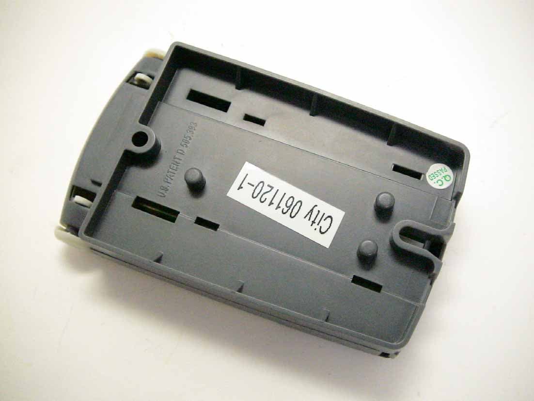
KJ80001071A
Jan 16, 2007Wireless Remote Control
Equipment Class
DSC - Part 15 Security/Remote Control Transmitter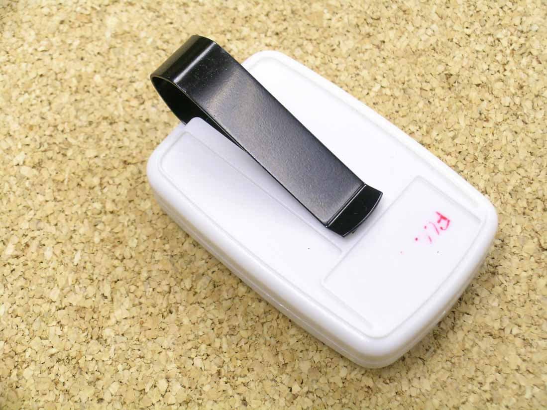
KJ80000593
Jan 16, 2007Wireless Keychain Remote Control
Equipment Class
DSC - Part 15 Security/Remote Control Transmitter