KKGF5RF5R
Digital Control Inc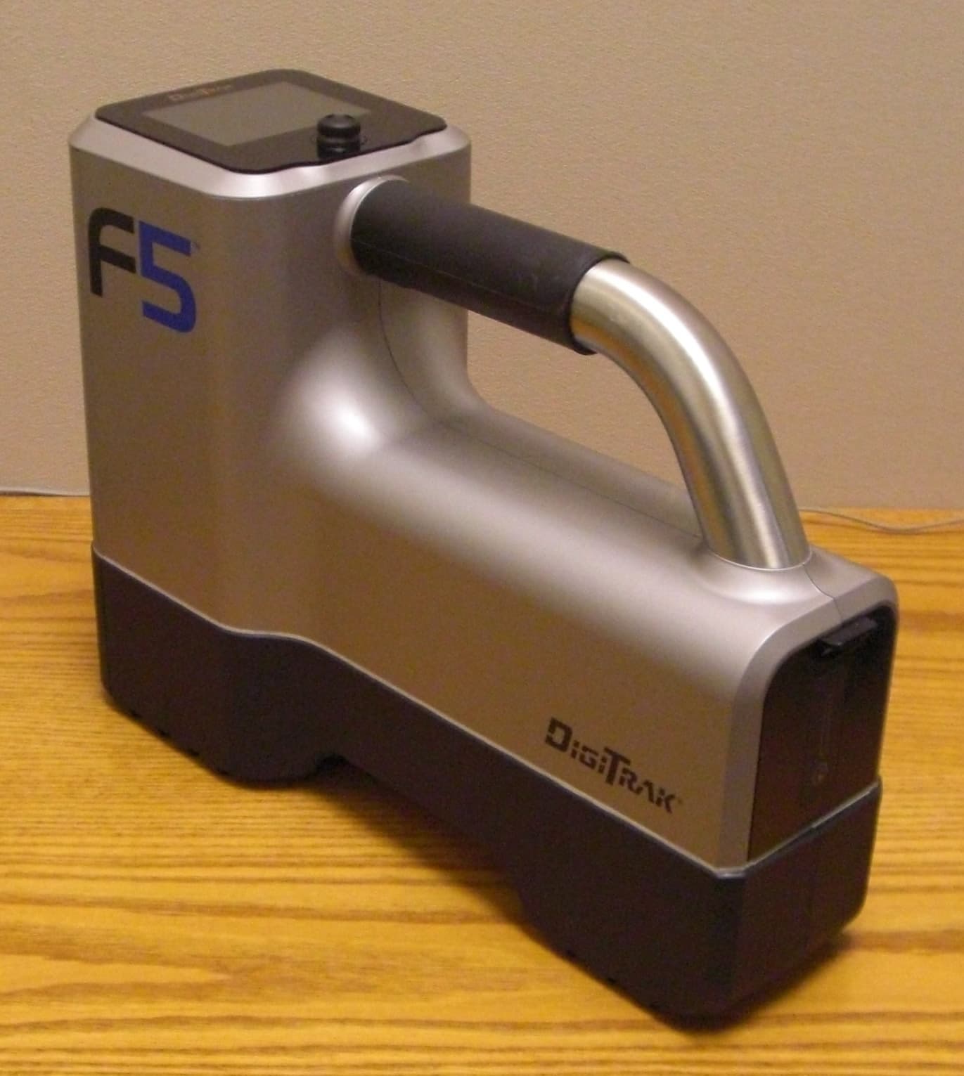
Click to zoom
Application Details
- Equipment Class
- TNB - Licensed Non-Broadcast Station Transmitter
- Date of Grant
- Oct 12, 2010
- Application Purpose
- Original Equipment
- Date of Application
- Oct 12, 2010
- Equipment Note
- F5R
- Frequency Range
- 464.50000000 - 469.55000000
- Company
- Digital Control Inc
- Country
- United States
Documents & Files
Document Text
Text extracted from the exhibit documents filed with the FCC. Open a document above to read the original.
Users Manual
DIGITAL CONTROL I NCORPORATED F5 Directional Drilling Locating System User Guide Digital Control Inc. Customer Service Contact Information: DCI Headquarters 19625 62nd Ave. S., Suite B-103 Kent, Washington 98032 USA Tel 425 251 0559 / 800 288 3610 Fax 253 395 2800 E-mail [email protected] www.digitrak.com DCI Europe Kurmainzer Strasse 56 D-97836 Bischbrunn Germany Tel +49(0) 9394 990 990 Fax +49(0) 9394 990 999 [email protected] DCI India DTJ 1023, DLF Tower A Jasola District Center New Delhi 110 044, India Tel +91(0) 11 4507 0444 Fax +91(0) 11 4507 0440 [email protected] DCI China No. 41, Lane 500, Xingle Road Huacao Town, Minhang District Shanghai P.R.C. 201107 Tel +86(0) 21 6432 5186 Fax +86(0) 21 6432 5187 [email protected] DCI Australia 2/9 Frinton Street Southport, Queensland 4215 Australia Tel +61(0) 7 5531 4283 Fax +61(0) 7 5531 2617 [email protected] DCI Russia 420059 Pavlyukhina Street 104, Kazan Russia Tel +7 843 277 52 22 Fax +7 843 277 52 07 [email protected] DIGITAL CONTROL INCORPORATED DigiTrak ® F5 User Guide 1 3-XXXX-00-P © 2010 by Digital Control Incorporated. All rights reserved. September 2010. Trrrrrrrrr Trademarks The DCI logo, DataLog ® , DigiTrak ® , Eclipse ® , MFD ® , SST ® , target-in-the-box ® , Target Steering ® , and TensiTrak ® are U.S. registered trademarks and DucTrak ™ , F Series ™ , FSD ™ , FasTrak ™ , F5 ™ , SE ™ , and SuperCell ™ are trademarks of Digital Control Incorporated. Prrrrrr Patents The DigiTrak ® F5 ™ Locating System is covered by one or more of the following U.S. Patents: 6,653,837; 6,693,429; 6,756,784; 6,768,307; 6,838,882; 6,924,645; 7,061,244; 7,080,698; 7,154,273; 7,159,672; 7,167,005; 7,176,690; 7,304,479; 7,309,990; 7,345,486. Sale of a DigiTrak ® F5 receiver does not convey a license under any patents covering the DigiTrak ® transmitter or underground drill housing. Other patents pending. Lrrrrrr Wrrrrrrr Limited Warranty All products manufactured and sold by Digital Control Incorporated (DCI) are subject to the terms of a Limited Warranty. A copy of the Limited Warranty is included with your DigiTrak® F2® Locating System; it can also be obtained by contacting DCI Customer Service, 800-288-3610 or 425-251-0559, or by connecting to DCI's website, www.digitrak.com . Irrrrrrrr Nrrrrr Important Notice All statements, technical information, and recommendations related to the products of DCI are based on information believed to be reliable, but the accuracy or completeness thereof is not warranted. Before utilizing any DCI product, the user should determine the suitability of the product for its intended use. All statements herein refer to DCI products as delivered by DCI and do not apply to any user customizations not authorized by DCI nor to any third-party products. Nothing herein shall constitute any warranty by DCI nor will anything herein be deemed to modify the terms of DCI’s existing Limited Warranty applicable to all DCI products. FCC Compliance Statement This equipment complies with Part 15 of the FCC Rules. Operation is subject to the following two conditions : (1) this equipment may not cause harmful interference, and (2) this equipment must accept any interference received, including interference that may cause undesired operation. DCI is responsible for FCC compliance in the United States: Digital Control Incorporated, 19625 62 nd Ave. S., Suite B-103, Kent, WA 98032; phone 425-251-0059 or 800-288-3610. Changes or modifications to the DCI equipment not expressly approved and carried out by DCI will void the user’s Limited Warranty and the FCC authorization to operate the equipment. DIGITAL CONTROL INCORPORATED DigiTrak ® F5 User Guide 2 Battery Disposal This symbol on equipment indicates that the equipment must not be disposed of with your other household waste. Instead, it is your responsibility to dispose of such equipment by handing it over to a designated collection point for the recycling of batteries or electrical and electronic equipment. If the equipment contains a banned substance, the label will show the pollutant (Cd = Cadmium; Hg = Mercury; Pb = Lead) near this symbol. The separate collection and recycling of your waste equipment at the time of disposal will help to conserve natural resources and ensure that it is recycled in a manner that protects human health and the environment. For more information about where you can drop off your waste equipment for recycling, please contact your local city office, your household waste disposal service, or the shop where you purchased the equipment. Safety Precautions Read this manual. If you have any questions about the operation of this or any DigiTrak equipment, contact Digital Control Incorporated’s Customer Service Department at anytime day or night. See “Digital Control Inc. Contact Information:” on the title page of this guide. All operators must review and understand the safe and proper operation of drilling and locating equipment before using the DigiTrak F5 Locating System for directional drilling operations. Serious injury and death can result if underground drilling equipment makes contact with an underground utility such as a high-voltage electrical cable or a natural gas line. Substantial property damage and liability can result if underground drilling equipment makes contact with an underground utility such as a telephone, fiber-optic, water, or sewer line. Work slowdowns and cost overruns can occur if drilling operators do not use the drilling or locating equipment correctly to obtain proper performance The DigiTrak F2 equipment is not explosion-proof and should never be used near flammable or explosive substances. The DigiTrak F5 Horizontal Directional Drilling Locating System cannot be used to locate utilities. DIGITAL CONTROL INCORPORATED DigiTrak ® F5 User Guide 3 The battery charger provided with the DigiTrak F2 system is designed with adequate safeguards to protect y…
Text truncated - open the document above for the full version.
Cover Letter(s)
Northwest EMC TCB Compliance Opinion Rev. 12/08/09 DIGC0098 Information about the Applicant Grantee (Company Name) Digital Control, Inc. FCC Contact Person Aaron Keyt Address 19625 62nd Avenue South, Suite B103 City, State, Zip Kent, WA 98032 Job Number DIGC0098 Model F5R FCC ID KKGF5R Agent Rudy Zeller, Stephen Anderson Approval Type Original Equipment Class LMS Part 90, Location & Monitoring Transmitter Rule Part 90 Overview This application is for a UHF transmitter used in a locator. The model F5R, handheld receiver, receives a low frequency (12 kHz) signal from an underground drill head and transmits information to the drill operator, via the UHF Transmitter, FCC ID: KKGF5R. The radio used in the F5R is identical to the radio in the F2R, which was previously certified. Test report data for direct connect measurements supplied in Report-DIGC0046.pdf are used for this application for the certification of the F5R device. The F5R receiver also contains an approved Bluetooth radio module, FCC ID: X3ZBTMOD1. Confidentiality requested for allowed files. Request is properly addressed and referenced. Letters assigning Rudy Zeller and\or Steve Anderson as agents was received. Recommendation All items have been resolved and completed to my satisfaction; therefore I recommend this application for approval. Signature 9/22/2010 Dave Tolman, TCB Committee
External Photos
F5 Receiver (F5R) External Photos Rear angled view Left Side View Right Side View Top and Bottom Views Front View
ID Label/Location Info
F5 Receiver (F5R) Label and Location Labels are located inside the battery compartment Remove battery to view labels inside battery compartment Labels shown inside battery compartment Label close ups
Internal Photos
F5 Receiver Internal Photos Front Cover Off Display module Telemetry antenna Card cage cover KHz antenna cluster Front cover off showing placement of telemetry antenna and display module Display module Telemetry antenna Front cover off showing placement of telemetry antenna and connection to transmitter Telemetry antenna Telemetry antenna connection to transmitter Card cage cover off Card cage Back plane Power Supply/ Telemetry board Transmitter shield DSP board DSP Board - top DSP board - bottom Power supply/telemetry controller board - top Power Supply shield Transmitter shield Power supply/telemetry controller board - top with radio shield removed Power supply/telemetry controller board - top with radio and power supply shield removed Power Supply/telemetry controller board - bottom Power Supply shield Power Supply/telemetry controller board – bottom power supply shield removed Radio top Radio bottom (upper) and top with shields removed (lower) Back plane top Back plane bottom Display assembly Display assembly cover removed Display board top Display board bottom Telemetry antenna top Telemetry antenna bottom KHz receiver antenna cluster
Operational Description
NORTHWEST EMC EUT: F2R - UHF Dipole AntennaWork Order: DIGC0048 Serial Number: ADA ADate: Customer: Digital Control, Inc.Temperature: 22 Attendees: noneHumidity: 28% Project: NoneBarometric Pres.: 30.15 Tested by: Rod PeloquinPower: N/ AJob Site: EV01 TEST SPECIFICATIONSTest Method TEST PARAMETERS Antenna Height(s) (m)Test Distance (m) 3 COMMENTS EUT OPERATING MODES DEVIATIONS FROM TEST STANDARD Run # Configuration # Results Signature 0.00 270.00 180.00 90.00 Frequency470.00 Absolute Gain of Reference Antenna (dBi)1.80 Reference Antenna Relative Gain Max (dBuV/m)97.20 AUT Relative Gain Max (dBuV/m)95.50 Difference (Reference Antenna - AUT) (dB)1.70 AUT Setup Loss (dB)0.00 Maximum Absolute Gain of AUT (dBi)0.10 Correction Factor (Convert From Relative to Absolute Gain) (dB)95.40 Measurement Antenna Polarity Horizontal Antenna Under Test (AUT) PolarityY ABSOLUTE GAIN DATA SHEET 14 1 01/30/09 None Transmitting from signal generator Absolute Gain of AUT -40.0 -30.0 -20.0 -10.0 0.0 10.0 0 270 180 90 90° 270° 180° 0° Antenna
Operational Description
Here are some values taken from the general specification section Operating Voltage +7.2V DC Nominal 6-9 VDC Max. Range RF Power Output 100mW @ 7.2 VDC nominal, 120 mW maximum Current Drain 215mA max. @ 7.2 Vdc 25°C 225 mA max. 6.0 - 9.0 Vdc-30°C to +60° C Section 4 of the Tech. Manual contains a description of the actual circuitry on the radio module.
Operational Description
A 2 1 1 2 3X 1 "X" Antenna "Y" Antenna "Z" Antenna 33 "X" Antenna "Y" Antenna "Z" Antenna Antenna Orientation As Seen From The Front Of The Receiver Scale: 1:2 Notes: 1 Assemble antenna cluster as shown. Note sharp corners for reference. 2 Solder fillets between right angle pads in 12 places. 3 Attach Antenna Cable in location shown with Cable Tie, through hole, 1/2 inch from end of insulation. 4. Solder individual wires in locations shown on Sheet 2. 5. Twist colored wire pairs at 3 TPI up to the solder points. 6. All solder connections to be made with RoHS (lead free) compliant process. A10-8-10PRODUCTION RELEASEBLMM REVDATEDESCRIPTIONBYCK REVISIONS ITEM NO.PART NUMBERDESCRIPTIONQTY. 1460-0014-00F5 Receiver Depth Antenna Cable Assy1 2420-5000-00F5 Receiver Depth Antenna PWB3 3304-0511-00Cable Tie, 5.75 x .14 inch, Nylon1 BREAK ALL SHARP EDGES ALL MACHINED SURFACES TOLERANCES (EXCEPT AS NOTED) 63 RMS THIS DRAWING IS CONFIDENTIAL AND IS SUPPLIED WITH THE UNDERSTANDING THAT IT IS NOT SHOWN TO OTHER PERSONS OR COMPANIES WITHOUT THE WRITTEN CONSENT OF DIGITAL CONTROL, INC. DRAWN BY ENGINEER CHECKED BY SIGNED SCALE DATE TITLE DRAWING NUMBER REV SH OF 1 2 DECIMAL (Inches) X.XX = DECIMAL (Inches) X.XXX = X° = .010 .005 1 .003/.007 .002 INTERNAL RADIUS R.015 OF ALL FEATURES COMMON CENTERLINES D IGITAL C ONTROL I NCORPORATED 19625 62nd Ave. S. Suite B-103 Kent, Wa. 98032 1-800-288-3610 or (425)-251-0701 DCI Fax (425)-251-0702 Stargate Fax (253)-395-2828 www.Digital-Control.com = = = = A F5 Receiver Depth Antenna Assembly 610-5000-00 2:3 Third Angle Projection SHEET SIZE A 10-8-10 BL MM SA DETAIL A SCALE 1.5 : 1 Shield Drain 1 to SS Brown to S- Brown-White to S+ Shield Drain 2 to SS Orange to S- Orange-White to S+ Shield Drain 3 to SS Blue to S+ Blue-White to S- "X" Antenna "Z" Antenna "Y" Antenna Green-White to T+ Green to T- BREAK ALL SHARP EDGES ALL MACHINED SURFACES TOLERANCES (EXCEPT AS NOTED) 63 RMS THIS DRAWING IS CONFIDENTIAL AND IS SUPPLIED WITH THE UNDERSTANDING THAT IT IS NOT SHOWN TO OTHER PERSONS OR COMPANIES WITHOUT THE WRITTEN CONSENT OF DIGITAL CONTROL, INC. DRAWN BY ENGINEER CHECKED BY SIGNED SCALE DATE TITLE DRAWING NUMBER REV SH OF 2 2 DECIMAL (Inches) X.XX = DECIMAL (Inches) X.XXX = X° = .010 .005 1 .003/.007 .002 INTERNAL RADIUS R.015 OF ALL FEATURES COMMON CENTERLINES D IGITAL C ONTROL I NCORPORATED 19625 62nd Ave. S. Suite B-103 Kent, Wa. 98032 1-800-288-3610 or (425)-251-0701 DCI Fax (425)-251-0702 Stargate Fax (253)-395-2828 www.Digital-Control.com = = = = A F5 Receiver Depth Antenna Assembly 610-5000-00 2:3 Third Angle Projection SHEET SIZE A 10-8-10 BL MM SA
Parts List/Tune Up Info
Attestation from Digital Control: Currently we do not do any tuning of the radio module. We verify it’s functionality by making sure we can pick up the transmitted signal using a receiver tuned to the same frequency. We rely on the radio module manufacturer to provide us with a radio that is within the specified frequency and power requirements. It is possible with software to fine tune the carrier frequency, but we haven’t seen the need to do this. Basically, the radio either works or it doesn’t. Section 5 of the DM-3473 Synthesized 100mW UHF Data Module Technical Manual contains some detailed servicing / tuning information.
RF Exposure Info
Digital Control, Inc. F5 UHF Transmitter Report No. DIGC0098.2 Report Prepared By www.nwemc.com 1-888-EMI-CERT © 2010 Northwest EMC, Inc 22975 NW Evergreen Parkway Suite 400 Hillsboro, Oregon 97124 Certificate of Compliance May 1, 2010 Digital Control, Inc. Model: F5 UHF Transmitter Emissions Test Description Specification Test Method Pass/Fail Maximum Permissible Exposure FCC 2.1091:2009 OET Bulletin 65, Supplement C Ed 01-01 Pass Modifications made to the product See the Modifications section of this report Approved By: Don Facteau, IS Manager This report must not be used to claim product certification, approval, or endorsement by NVLAP, NIST, or any agency of the federal government of the United States of America. Product compliance is the responsibility of the client, therefore the tests and equipment modes of operation represented in this report were agreed upon by the client, prior to testing. This Report may only be duplicated in its entirety. The results of this test pertain only to the sample(s) tested. The specific description is noted in each of the individual sections of the test report supporting this certificate of test. Northwest EMC Revision History Revision 06/29/09 Barometric Pressure The recorded barometric pressure has been normalized to sea level. Revision Number Description Date Page Number 00 None Accreditations and Authorizations FCC Accredited by NVLAP for performance of FCC radio, digital, and ISM device testing. Our Open Area Test Sites, certification chambers, and conducted measurement facilities have been fully described in reports filed with the FCC and accepted by the FCC in letters maintained in our files. Northwest EMC has been accredited by ANSI to ISO / IEC Guide 65 as a product certifier. We have been designated by the FCC as a Telecommunications Certification Body (TCB). This allows Northwest EMC to certify transmitters to FCC specifications in accordance with 47 CFR 2.960 and 2.962. NVLAP Northwest EMC, Inc. is accredited under the United States Department of Commerce, National Institute of Standards and Technology, and National Voluntary Laboratory Accreditation Program for satisfactory compliance with the requirements of ISO/IEC 17025 for Testing Laboratories. The NVLAP accreditation encompasses Electromagnetic Compatibility Testing in accordance with the European Union EMC Directive 2004/108/EC, and ANSI C63.4. Additionally, Northwest EMC is accredited by NVLAP to perform radio testing in accordance with the European Union R&TTE Directive 1999/5/EEC, the requirements of FCC, and the RSS radio standards for Industry Canada. NVLAP LAB CODE 200629-0 NVLAP LAB CODE 200630-0 NVLAP LAB CODE 200676-0 NVLAP LAB CODE 200761-0 NVLAP LAB CODE 200881-0 Industry Canada Accredited by NVLAP for performance of Industry Canada RSS and ICES testing. Our Open Area Test Sites and certification chambers comply with RSS-Gen, Issue 2 and have been filed with Industry Canada and accepted. Northwest EMC has been accredited by ANSI to ISO / IEC Guide 65 as a product certifier. We have been designated by NIST and recognized by Industry Canada as a Certification Body (CB) per the APEC Mutual Recognition Arrangement (MRA). This allows Northwest EMC to certify transmitters to Industry Canada technical requirements. (Site Filing Numbers - Hillsboro: 2834D-1, 2834D-2, Sultan: 2834C-1, Irvine: 2834B-1, 2834B-2, Brooklyn Park: 2834E-1) CAB Designated by NIST and validated by the European Commission as a Conformity Assessment Body (CAB) to conduct tests and approve products to the EMC directive and transmitters to the R&TTE directive, as described in the U.S. - EU Mutual Recognition Agreement. NEMKO Assessed and accredited by NEMKO (Norwegian testing and certification body) for European emissions and immunity testing. As a result of NEMKO's laboratory assessment, they will accept test results from Northwest EMC, Inc. for product certification (Authorization No. ELA 119). Accreditations and Authorizations Australia/New Zealand The National Association of Testing Authorities (NATA), Australia has been appointed by the ACA as an accreditation body to accredit test laboratories and competent bodies for EMC standards. Accredited test reports or assessments by competent bodies must carry the NATA logo. Test reports made by an overseas laboratory that has been accredited for the relevant standards by an overseas accreditation body that has a Mutual Recognition Agreement (MRA) with NATA are also accepted as technical grounds for product conformity. The report should be endorsed with the respective logo of the accreditation body (NVLAP). VCCI Accepted as an Associate Member to the VCCI, Acceptance No. 564. Conducted and radiated measurement facilities have been registered in accordance with Regulations for Voluntary Control Measures, Article 8. (Registration Numbers. - Hillsboro: C-1071, R-1025, G-84, C-2687, T-1658, and R-2318, Irvine: R-1943, G-85, C- 2766, and T-1659, Sultan: R-871, G-83, C-1784, and T-1511, Brooklyn Park: R-3125, G-86, G-141, C-3464, and T-1634). BSMI Northwest EMC has been designated by NIST and validated by C-Taipei (BSMI) as a CAB to conduct tests as described in the APEC Mutual Recognition Agreement (US0017). License No.SL2-IN-E-1017. GOST Northwest EMC, Inc. has been assessed and accredited by the Russian Certification bodies Certinform VNIINMASH, CERTINFO, SAMTES, and Federal CHEC, to perform EMC and Hygienic testing for Information Technology Products. As a result of their laboratory assessment, they will accept test results from Northwest EMC, Inc. for product certification KCC Northwest EMC, Inc is a CAB designated by MRA partners and recognized by Korea. (Assigned Lab Numbers: Hillsboro: US0017, Irvine: US0158, Sultan: US0157) VIETNAM Vietnam MIC has approved Northwest EMC as an accredited test lab. Per Decision No. 194/QD-QLCL (dated December 15, 2009), Northwest EMC test reports can be used for Vietnam approval submissions. SCOPE For details on the Scopes of…
Text truncated - open the document above for the full version.
Test Report
Digital Control, Inc. F5 UHF Transmitter (F5R) Report No. DIGC0098 Report Prepared By www.nwemc.com 1-888-EMI-CERT © 2010 Northwest EMC, Inc 22975 NW Evergreen Parkway Suite 400 Hillsboro, Oregon 97124 Certificate of Test Last Date of Test: May 1, 2010 Digital Control, Inc. Model: F5 UHF Transmitter (F5R) Emissions Test Description Specification Test Method Pass/Fail Effective Radiated Power (ERP) FCC 90.217:2010 ANSI/TIA/EIA-603-C-2004 Pass Spurious Radiated Emissions FCC 90.217:2010 ANSI/TIA/EIA-603-C-2004 Pass Modifications made to the product See the Modifications section of this report Test Facility The measurement facility used to collect the data is located at: Northwest EMC, Inc. 22975 NW Evergreen Parkway, Suite 400 Hillsboro, OR 97124 Phone: (503) 844-4066 Fax: 844-3826 This site has been fully described in a report filed with and accepted by the FCC (Federal Communications Commission) and Industry Canada (Site filing #2834D-2). Approved By: Don Facteau, IS Manager NVLAP Lab Code: 200630-0 This report must not be used to claim product certification, approval, or endorsement by NVLAP, NIST, or any agency of the federal government of the United States of America. Product compliance is the responsibility of the client, therefore the tests and equipment modes of operation represented in this report were agreed upon by the client, prior to testing. This Report may only be duplicated in its entirety. The results of this test pertain only to the sample(s) tested. The specific description is noted in each of the individual sections of the test report supporting this certificate of test. Northwest EMC Revision History Revision 06/29/09 Barometric Pressure The recorded barometric pressure has been normalized to sea level. Revision Number Description Date Page Number 00 None Accreditations and Authorizations FCC Accredited by NVLAP for performance of FCC radio, digital, and ISM device testing. Our Open Area Test Sites, certification chambers, and conducted measurement facilities have been fully described in reports filed with the FCC and accepted by the FCC in letters maintained in our files. Northwest EMC has been accredited by ANSI to ISO / IEC Guide 65 as a product certifier. We have been designated by the FCC as a Telecommunications Certification Body (TCB). This allows Northwest EMC to certify transmitters to FCC specifications in accordance with 47 CFR 2.960 and 2.962. NVLAP Northwest EMC, Inc. is accredited under the United States Department of Commerce, National Institute of Standards and Technology, and National Voluntary Laboratory Accreditation Program for satisfactory compliance with the requirements of ISO/IEC 17025 for Testing Laboratories. The NVLAP accreditation encompasses Electromagnetic Compatibility Testing in accordance with the European Union EMC Directive 2004/108/EC, and ANSI C63.4. Additionally, Northwest EMC is accredited by NVLAP to perform radio testing in accordance with the European Union R&TTE Directive 1999/5/EEC, the requirements of FCC, and the RSS radio standards for Industry Canada. NVLAP LAB CODE 200629-0 NVLAP LAB CODE 200630-0 NVLAP LAB CODE 200676-0 NVLAP LAB CODE 200761-0 NVLAP LAB CODE 200881-0 Industry Canada Accredited by NVLAP for performance of Industry Canada RSS and ICES testing. Our Open Area Test Sites and certification chambers comply with RSS-Gen, Issue 2 and have been filed with Industry Canada and accepted. Northwest EMC has been accredited by ANSI to ISO / IEC Guide 65 as a product certifier. We have been designated by NIST and recognized by Industry Canada as a Certification Body (CB) per the APEC Mutual Recognition Arrangement (MRA). This allows Northwest EMC to certify transmitters to Industry Canada technical requirements. (Site Filing Numbers - Hillsboro: 2834D-1, 2834D-2, Sultan: 2834C-1, Irvine: 2834B-1, 2834B-2, Brooklyn Park: 2834E-1) CAB Designated by NIST and validated by the European Commission as a Conformity Assessment Body (CAB) to conduct tests and approve products to the EMC directive and transmitters to the R&TTE directive, as described in the U.S. - EU Mutual Recognition Agreement. NEMKO Assessed and accredited by NEMKO (Norwegian testing and certification body) for European emissions and immunity testing. As a result of NEMKO's laboratory assessment, they will accept test results from Northwest EMC, Inc. for product certification (Authorization No. ELA 119). Accreditations and Authorizations Australia/New Zealand The National Association of Testing Authorities (NATA), Australia has been appointed by the ACA as an accreditation body to accredit test laboratories and competent bodies for EMC standards. Accredited test reports or assessments by competent bodies must carry the NATA logo. Test reports made by an overseas laboratory that has been accredited for the relevant standards by an overseas accreditation body that has a Mutual Recognition Agreement (MRA) with NATA are also accepted as technical grounds for product conformity. The report should be endorsed with the respective logo of the accreditation body (NVLAP). VCCI Accepted as an Associate Member to the VCCI, Acceptance No. 564. Conducted and radiated measurement facilities have been registered in accordance with Regulations for Voluntary Control Measures, Article 8. (Registration Numbers. - Hillsboro: C-1071, R-1025, G-84, C-2687, T-1658, and R-2318, Irvine: R-1943, G-85, C- 2766, and T-1659, Sultan: R-871, G-83, C-1784, and T-1511, Brooklyn Park: R-3125, G-86, G-141, C-3464, and T-1634). BSMI Northwest EMC has been designated by NIST and validated by C-Taipei (BSMI) as a CAB to conduct tests as described in the APEC Mutual Recognition Agreement (US0017). License No.SL2-IN-E-1017. GOST Northwest EMC, Inc. has been assessed and accredited by the Russian Certification bodies Certinform VNIINMASH, CERTINFO, SAMTES, and Federal CHEC, to perform EMC and Hygienic testing for Information Technology Products. As a result of their laboratory assessment, they will acc…
Text truncated - open the document above for the full version.
Test Report
Digital Control, Inc. F2 Receiver (F2R) Report No. DIGC0046 Report Prepared By www.nwemc.com 1-888-EMI-CERT © 2009Northwest EMC, Inc 22975 NW Evergreen Parkway Suite 400 Hillsboro, Oregon 97124 Certificate of Test Last Date of Test: January 26, 2009 Digital Control, Inc. Model: F2 Receiver (F2R) Emissions Test Description Specification Test Method Pass/Fail Output Power FCC 2.1046:2009, FCC 90.217:2009 ANSI/TIA/EIA-603-C-2004 Pass Spurious Radiated Emissions FCC 2.1053:2009, FCC 90.217:2009 ANSI/TIA/EIA-603-C-2004 Pass Occupied Bandwidth FCC 2.1049:2009, FCC 90.217:2009 ANSI/TIA/EIA-603-C-2004 Pass Frequency Stability FCC 2.1055:2009, FCC 90.217:2009 ANSI/TIA/EIA-603-C-2004 Pass Spurious Conducted Emissions FCC 2.1051:2009, FCC 90.217:2009 ANSI/TIA/EIA-603-C-2004 Pass Emission Mask FCC 2.1049:2009, FCC 90.217:2009 ANSI/TIA/EIA-603-C-2004 Pass Modifications made to the product See the Modifications section of this report Test Facility The measurement facility used to collect the data is located at: Northwest EMC, Inc. 22975 NW Evergreen Parkway, Suite 400 Hillsboro, OR 97124 Phone: (503) 844-4066 Fax: 844-3826 This site has been fully described in a report filed with and accepted by the FCC (Federal Communications Commission) and Industry Canada (Site filing #2834D-2). Approved By: Don Facteau, IS Manager NVLAP Lab Code: 200630-0 This report must not be used to claim product certification, approval, or endorsement by NVLAP, NIST, or any agency of the federal government of the United States of America. Product compliance is the responsibility of the client, therefore the tests and equipment modes of operation represented in this report were agreed upon by the client, prior to testing. This Report may only be duplicated in its entirety. The results of this test pertain only to the sample(s) tested. The specific description is noted in each of the individual sections of the test report supporting this certificate of test. Northwest EMC Revision History Revision 05/05/03 Revision Number Description Date Page Number 00 None Northwest EMC Accreditations and Authorizations Revision 03/18/05 FCC: Accredited by NVLAP for performance of FCC radio, digital, and ISM device testing. Our Open Area Test Sites, certification chambers, and conducted measurement facilities have been fully described in reports filed with the FCC and accepted by the FCC in letters maintained in our files. Northwest EMC has been accredited by ANSI to ISO / IEC Guide 65 as a product certifier. We have been designated by the FCC as a Telecommunications Certification Body (TCB). This allows Northwest EMC to certify transmitters to FCC specifications in accordance with 47 CFR 2.960 and 2.962. NVLAP: Northwest EMC, Inc. is accredited under the United States Department of Commerce, National Institute of Standards and Technology, and National Voluntary Laboratory Accreditation Program for satisfactory compliance with the requirements of ISO/IEC 17025 for Testing Laboratories. The NVLAP accreditation encompasses Electromagnetic Compatibility Testing in accordance with the European Union EMC Directive 2004/108/EC, and ANSI C63.4. Additionally, Northwest EMC is accredited by NVLAP to perform radio testing in accordance with the European Union R&TTE Directive 1999/5/EEC, the requirements of FCC, and the RSS radio standards for Industry Canada. NVLAP LAB CODE 200629-0 NVLAP LAB CODE 200630-0 NVLAP LAB CODE 200676-0 NVLAP LAB CODE 200761-0 Industry Canada: Accredited by NVLAP for performance of Industry Canada RSS and ICES testing. Our Open Area Test Sites and certification chambers comply with RSS-Gen, Issue 2 and have been filed with Industry Canada and accepted. Northwest EMC has been accredited by ANSI to ISO / IEC Guide 65 as a product certifier. We have been designated by NIST and recognized by Industry Canada as a Certification Body (CB) per the APEC Mutual Recognition Arrangement (MRA). This allows Northwest EMC to certify transmitters to Industry Canada technical requirements. ( Site Filing Numbers - Hillsboro: 2834D-1, 2834D-2, Sultan: 2834C-1, Irvine: 2834B-1, 2834B-2) CAB: Designated by NIST and validated by the European Commission as a Conformity Assessment Body (CAB) to conduct tests and approve products to the EMC directive and transmitters to the R&TTE directive, as described in the U.S. - EU Mutual Recognition Agreement. Northwest EMC Accreditations and Authorizations Revision 03/18/05 NEMKO: Assessed and accredited by NEMKO (Norwegian testing and certification body) for E…
Text truncated - open the document above for the full version.
Contact Information
Applicant
Thomas J. Hall(General Counsel)
Test Firm
Northwest EMC, Inc.Greg Kiemel
Technical Specifications
| # | Rule Parts | Frequency Range | Power Output | Emission | Tolerance |
|---|---|---|---|---|---|
| 1 | 90.217(b) | 464.5 MHz - 469.55 MHz | 108.80 mW | 10K2F1D | 0.5100000000 ppm |
Other Applications from Digital Control Inc
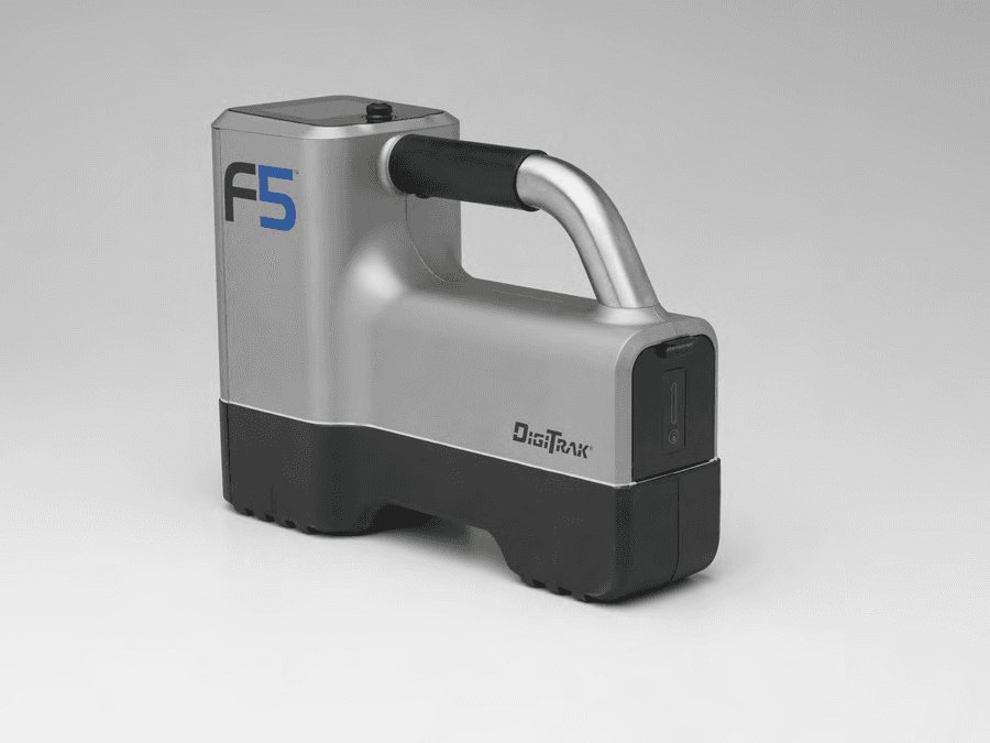
KKGB2DIG1
Aug 28, 2013DR2
Equipment Class
TNB - Licensed Non-Broadcast Station Transmitter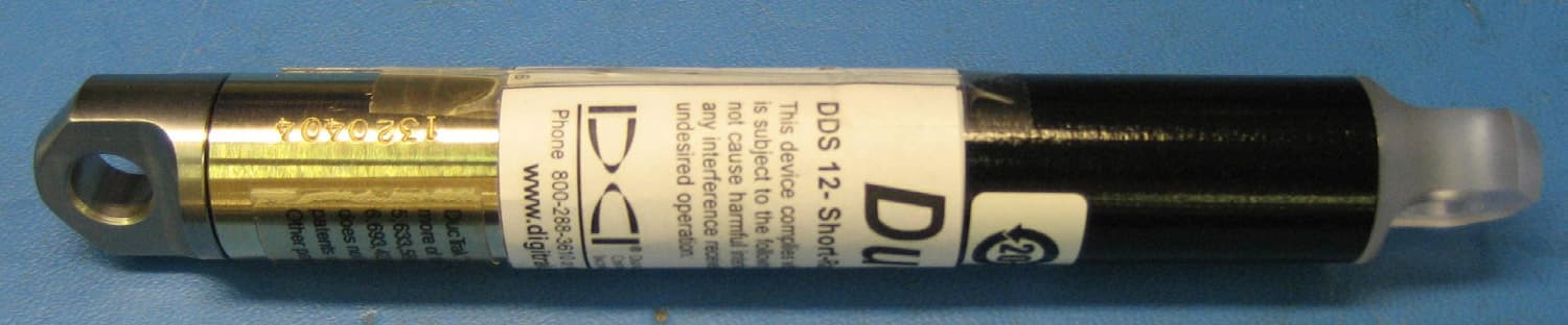
KKGA040412
Sep 21, 2011DDS 12, DDT 12
Equipment Class
DCD - Part 15 Low Power Transmitter Below 1705 kHz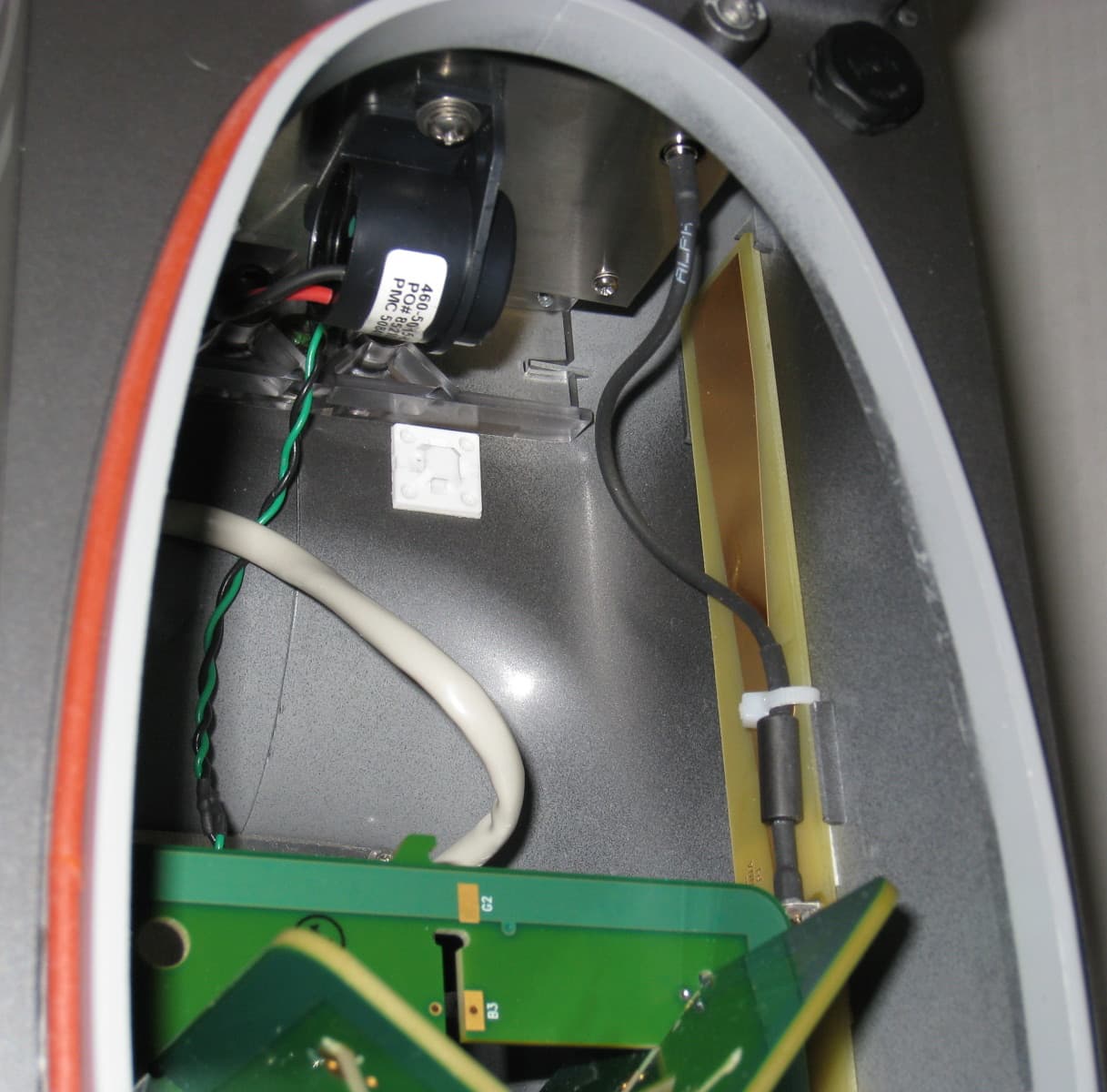
KKGB1DIG1
Jul 11, 2011DigiRadio
Equipment Class
TNB - Licensed Non-Broadcast Station Transmitter
KKG50416
Apr 13, 2011F5Dp 19/12, F5Dp 12/1.3, F5DLp 19/12
Equipment Class
DCD - Part 15 Low Power Transmitter Below 1705 kHz
KKGA050316
Apr 03, 2011ECP, FC
Equipment Class
DCD - Part 15 Low Power Transmitter Below 1705 kHz