KNFWSS1Wireless Magnetic Sensor
SPAL USA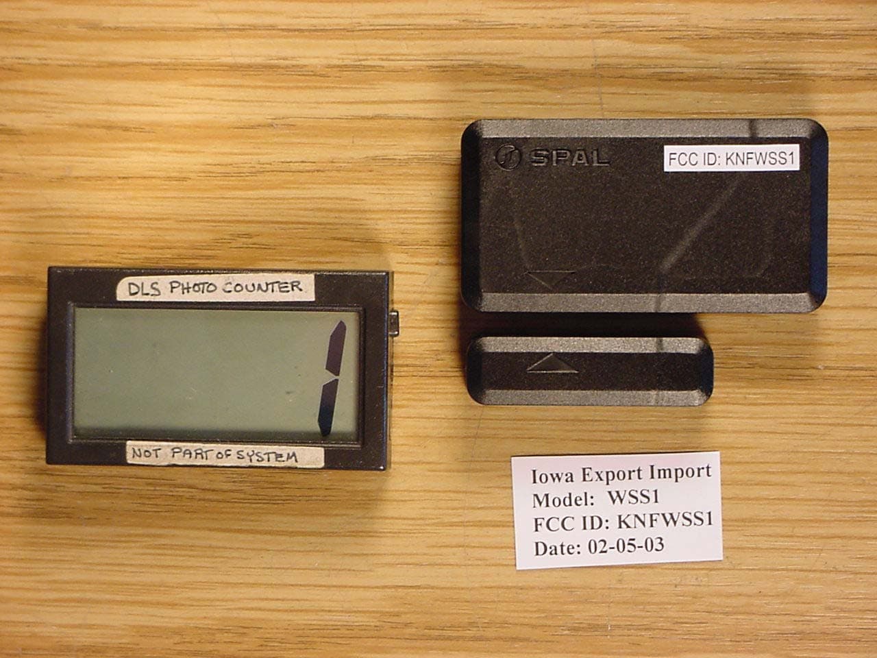
Click to zoom
Application Details
- Equipment Class
- DXX - Part 15 Low Power Communication Device Transmitter
- Date of Grant
- Mar 24, 2003
- Application Purpose
- Original Equipment
- Date of Application
- Mar 24, 2003
- Equipment Note
- Wireless Magnetic Sensor
- Frequency Range
- 433.96000000 - 433.96000000
- Company
- SPAL USA
- Country
- United States
Documents & Files
Document Text
Text extracted from the exhibit documents filed with the FCC. Open a document above to read the original.
Users Manual
Page 1 of 1 SPAL WSS Wireless Sensor User’s Manual ROUGH DRAFT (March 25, 2003) Table of Contents 1. Introduction, p. 1 2. FCC Statement, p. 1 3. Technical Specifications, p. 1 Introduction The SPAL WSS Wireless Sensor is to be used with the SPAL AS-80 Security System. Up to 10 sensors may be programmed into a single AS-80 system. The WSS Wireless Magnetic Sensor (SPAL part 35600022) comes as two parts, a sensor/transmitter and a magnet. The transmitter sends out an alarm signal when the magnet is separated from the sensor. This system is similar to what is in your recent-model cars, alerting that a door ajar. It can be installed in all types of vans, mobile homes, recreational vehicles, cars and trucks. The WSS is also ideal for utility trucks with multiple compartments and businesses having several entry/exit doors. The WSS can also be configured to protect garages, windows and doors in homes and businesses. The WSS sensors configure into the system as extra transmitters, so up to 10 WSS sensors can be added to a single AS-80 alarm system. Each unit installs with screws and/or WSS- specific two-sided adhesive tape. FCC Statements This device complies with part 15 of the FCC Rules. Operation is subject to the following two conditions: (1) This device may not cause harmful interference, and (2) This device must accept any interference received, including interference that may cause undesired operation. The user is caution that any changes or modifications not expressly approved by the party responsible for compliance could void the user’s authority to operate the equipment. Technical Specifications Each sensor/transmitter measures just 2.4 x 1.25 x 0.5 inches (60x32x12 mm) and the magnet is just 0.5 x 1.6 x 0.5 inches (12x41x12 mm). The range of the transmitters is 100- 130 feet (30-40 meters). The operating units will function in temperatures of -22° to 140° F (- 30° to 60° C). Because of the long-life lithium battery, the WSS sensor will function for up to four years.
Cover Letter(s)
FCC ID: KNFWSS1 D.L.S. ELECTRONIC SYSTEMS, INC. 1250 Peterson Drive Wheeling, Illinois 60090 FCC Authorization & Evaluation Division 7435 Oakland Mills Road Columbia, Maryland 21045-0429 Gentlemen: We are submitting for Iowa Export-Import, an Wireless Sensor/transmitter, Model Number WSS1, with a FCC ID: KNFWSS1 for certification. This unit has been tested and complies to Part 15, Subpart C. If there are any questions in regards to this application, please call D.L.S. Electronic Systems, Inc. at (847) 537 6400. Enclosed you will find a copy of our test report with the information and results of tests that is required under Part 15, Section 15.231. Thank you for your assistance in this matter. Sincerely, Arnom C. Rowe EMC-001375-NE
External Photos
FCC ID: KNFWSS1 TOP VIEW FCC ID: KNFWSS1 BOTTOM VIEW
ID Label/Location Info
The FCC ID will be placed on the bottom of the product as shown in the picture labeled Bottom view. SPAL is written on the top of the product as shown below. The text will be molded into or screen-printed on the case of the product.
Internal Photos
FCC ID: KNFWSS1 TOP COVER & MAGNET REMOVED FCC ID: KNFWSS1 CIRCUIT BOARD - SIDE 1 FCC ID: KNFWSS1 CIRCUIT BOARD - SIDE 2 FCC ID: KNFWSS1
Test Report
1250 Peterson Dr., Wheeling, IL 60090 Page - 1 - Company: Iowa Export-Import Model Tested: WSS1 Report Number: 10035 FCC Rules and Regulations / Intentional Radiators Periodic operational in the 40.66-40.70 MHz Band and above 70 MHz. Part 15, Subpart C, Section 15.231 THE FOLLOWING ''MEETS'' THE ABOVE TEST SPECIFICATION THE CONDUCTED EMISSIONS TESTS WAS NOT RUN SINCE THIS DEVICE IS BATTERY OPERATED Formal Name: WSS Magnetic Wireless Sensor Kind of Equipment: Wireless Sensor/transmitter Test Configuration: Tested at 3 vdc Model Number(s): WSS1 Model(s) Tested: WSS1 Serial Number(s): NA Date of Tests: February 3, 4 & 10, 2003 Test Conducted For: Iowa Export-Import 512 Tuttle Street Des Moines, Illinois 50309 NOTICE: “This report must not be used by the client to claim product endorsement by NVLAP or any agency of the U.S. Government”. Please see the "Additional Description of Equipment Under Test" page listed inside of this report. This report must not be reproduced (except in full), without the approval of D.L.S. Electronic Systems. 1250 Peterson Dr., Wheeling, IL 60090 Page - 2 - Company: Iowa Export-Import Model Tested: WSS1 Report Number: 10035 SIGNATURE PAGE Report By: Arnom C. Rowe Test Engineer EMC-001375-NE Reviewed By: William Stumpf OATS Manager Approved By: Brian Mattson General Manager Company Official: Iowa Export-Import 1250 Peterson Dr., Wheeling, IL 60090 Page -3- Company: Iowa Export-Import Model Tested: WSS1 Report Number: 10035 1250 Peterson Dr., Wheeling, IL 60090 Page -4- Company: Iowa Export-Import Model Tested: WSS1 Report Number: 10035 1250 Peterson Dr., Wheeling, IL 60090 Page -5- Company: Iowa Export-Import Model Tested: WSS1 Report Number: 10035 1250 Peterson Dr., Wheeling, IL 60090 Page -6- Company: Iowa Export-Import Model Tested: WSS1 Report Number: 10035 1250 Peterson Dr., Wheeling, IL 60090 Page -7- Company: Iowa Export-Import Model Tested: WSS1 Report Number: 10035 TABLE OF CONTENTS i. Cover Page ...........................................................................................................................1 ii. Signature Page .....................................................................................................................2 iii. NVLAP Certificate of Accreditation ...................................................................................3 iv. NVLAP Scope of Accreditation ..........................................................................................4 v. Table of Contents .................................................................................................................7 1.0 Summary of Test Report ......................................................................................................9 2.0 Introduction..........................................................................................................................9 3.0 Object ...................................................................................................................................9 4.0 Test Set-Up ........................................................................................................................10 5.0 Test Equipment ..................................................................................................................11 6.0 Conducted Emission Measurements ..................................................................................12 7.0 Radiated Emission Measurements .....................................................................................13 8.0 Description of Test Sample................................................................................................15 8.0 Additional Description of Test Sample..............................................................................16 8.0 Description of Test Sample................................................................................................17 9.0 Additional Description of Test Sample..............................................................................18 10.0 Photo Information and Test Set-Up ...................................................................................19 11.0 Radiated Photos Taken During Testing .............................................................................20 12.0 Results of Tests ..................................................................................................................22 13.0 Conclusion .........................................................................................................................22 TABLE 1 – EQUIPMENT LIST ...................................................................................................23 1250 Peterson Dr., Wheeling, IL 60090 Page -8- Company: Iowa Export-Import Model Tested: WSS1 Report Number: 10035 TABLE OF CONTENTS Appendix A – Electric Field Radiated Emissions Test..................................................................25 1.0 Bandwidths ........................................................................................................................26 1.0 Graph(s) taken of the Fundamental Frequency and Bandwidth ........................................27 2.0 Field Strength of Spurious Emission Measurements .........................................................29 2.0 Radiated Data and Charts Taken of the Spurious Emissions During Testing ...................30 3.0 Pulsed Operation (Duty Cycle Correction Factor).............................................................43 3.0 Graph(s) taken of the Pulsed Operation (DCCF)...............................................................44 4.0 Restricted Bands ................................................................................................................48 1250 Peterson Dr., Wheeling, IL 60090 Page -9- Company: Iowa Export-Import Model Tested: WSS1 Report Number: 10035 1.0 SUMMARY OF TEST REPORT It was found that the WSS Magnetic Wireless Sensor, Model Number(s) WSS1, ''meets'' th…
Text truncated - open the document above for the full version.
Test Setup Photos
PHOTOS TAKEN DURING TESTING SHOWING THE TEST SET PHOTOS TAKEN DURING TESTING SHOWING THE TEST SET
Contact Information
Applicant
Dan McNeal(QC/Engineering Manager)
Technical Contact
DLS Electronic Systems, Inc.Arnom Rowe
[email protected]847-537-6400
1250 Peterson Drive · Wheeling, Illinois · United States
Test Firm
DLS Electronic Systems, Inc.William Stumpf
Technical Specifications
| # | Rule Parts | Frequency Range | Power Output |
|---|---|---|---|
| 1 | 15C | 433.96 MHz - 433.96 MHz | - |
Other Applications from SPAL USA
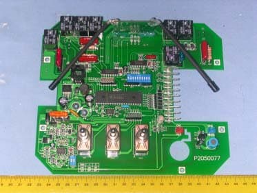
KNF6RX
Mar 26, 2006Remote Control Receiver
Equipment Class
CYY - Communications Receiver used w/Pt 15 Transmitter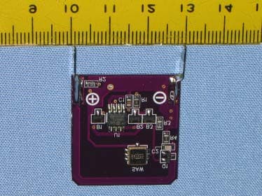
KNF4TX433
Oct 26, 2005AUTOMATED CONTROL
Equipment Class
DSC - Part 15 Security/Remote Control Transmitter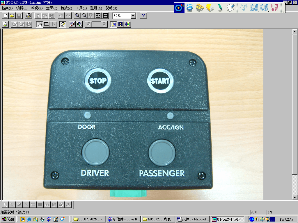
KNFUTRX
Sep 28, 2005Automated Control
Equipment Class
DXX - Part 15 Low Power Communication Device Transmitter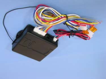
KNFRCU6RX
Sep 26, 2004REMOTE CONTOLLER (RX)
Equipment Class
CXX - Communications Rcvr for use w/ licensed Tx and CBs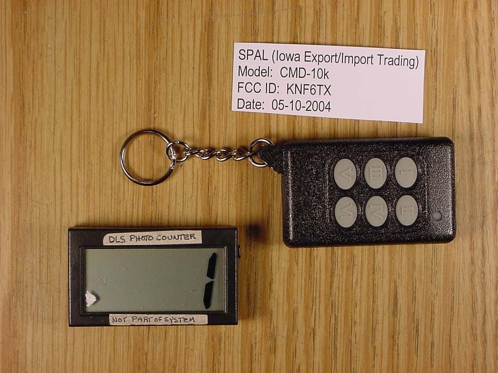
KNF6TX
Jul 05, 2004Automotive Aftermarket Transmitter
Equipment Class
DSC - Part 15 Security/Remote Control Transmitter