KRE-E2-IP-PA500AHECLIPSE IP POWER AMPLIFIER
RF Technology Pty Ltd
Click to zoom
Application Details
- Equipment Class
- TNB - Licensed Non-Broadcast Station Transmitter
- Date of Grant
- Jul 27, 2021
- Application Purpose
- Original Equipment
- Date of Application
- Jul 27, 2021
- Equipment Note
- ECLIPSE IP POWER AMPLIFIER
- Frequency Range
- 406.10000000 - 420.00000000
- Company
- RF Technology Pty Ltd
- Country
- Australia
Documents & Files
Document Text
Text extracted from the exhibit documents filed with the FCC. Open a document above to read the original.
Users Manual
Eclipse2 Se ptember 2019 [email protected] E2-IP- · PA 500AH Amplifier Operation and Maintenance Manual This manual is produced by RF Technology Pty. Ltd. 46/7 Sefton Road, Thornleigh, 2120, Australia Copyright © 2012 RF Technology Pty. Ltd. RF Technology Page 2 CONTENTS CONTENTS Contents 1 Operating Instructions 1.1 Installation 4 4 1.1.1 Sub-rack Wiring Guidelines 4 1.2 Front Panel Indicators 5 1.3 Internal Adjustments 5 1.4 Amplifier I/O Connections 5 1.4.1 RF Input 6 1.4.2 RF Output 6 1.4.3 25 Pin Connector 6 1.4.4 RJ45 Ethernet Connector 6 2 Circuit Description 2.1 Amplifiers 6 6 2.2 Power Splitter / Combiners 7 2 .3 Directional Coupler 7 2.4 Low Pass Filter 7 2 .5 Power Control Circuits 7 2.6 RF Output Indicator 8 2.7 Over Temperature Protection 8 3 Field Alignment Procedures 8 3.1 Output Power Level 8 3 .2 Tuning Procedure 8 4 Specifications 4.1 General Specifications 9 9 4.2 Physical Configuration 10 4.3 Front Panel Indicators and Test Points 10 4.3.1 Indicators 10 4.3.2 Test Points 4.4 Electrical Specifications 10 10 4.4.1 Power Requirements 10 4.4.2 Frequency Range 10 4.5 Antenna Impedance 11 4.6 Output Power 4.6.1 Transmit Duty Cycle 11 11 4.7 Spurious and Harmonics 11 4.8 Heatsink Temperature 11 4.9 ALC Output 11 4.10 Connectors 11 4.10.1 RF Input 11 4.10.2 RF Output 12 4.10.3 25-Pin Connector12 4.10.4 USB Connector12 E2-IP-PA 500AH RF Technology E2-IP-PA 500AH Page 3 CONTENTS CONTENTS A Engineering DiagramsAttachment A.1 Functional Diagrams1 A.2 Wiring Diagrams2 Page 4 RF Technology 1 OPERATING INSTRUCTIONS 1.1 Installation WARNING Changes or modifications not expressly approved by RF Technology could void your authority to operate this equipment. Specifications may vary from those given in this document in accordance with requirements of local authorities. RF Technology equipment is subject to continual improvement and RF Technology reserves the right to change performance and specification without further notice. 1 Operating Instructions The IP • PA500AH is part of the Eclipse2 range of modular base station equipment. It is a broadband Solid State Internet Protocol RF Power Amplifier (SS • IP • PA) capable of delivering over 100 Watts in the UHF frequency range. It is designed to complement the Eclipse2 Software Defined Radio (SDR), and mounts in a standard Eclipse sub-rack. 1.1 Installation There are no front panel controls. In normal circumstances no alignment or setup is required. If mounted in a sub-rack that has not previously been wired for a power amplifier, the rack connector must be wired according to the guidelines in section 1.1.1 below. 1.1.1 Sub-rack Wiring Guidelines When installing an Eclipse Power Amplifier in an Eclipse sub-rack, observe the following guidelines for sub-rack installation: The sub-rack power supply must be capable of delivering the full current requirements for all modules fitted in the sub-rack, typically 20 Amperes for a 100W basestation/amplifier. Owing to the current drain, power supply lines should be cabled to the power amplifier separately and using heavy gauge wire to minimise voltage drop and interference via the power supply of other modules in the rack. E2-IP-PA 500AH RF Technology • Page 5 1 OPERATING INSTRUCTIONS 1.3 Internal Adjustments 1 .2 Front Panel Indicators PWR LED The power (PWR) LED shows that the dc supply is connected to the amplifier. RFO LED The RF output (RFO) LED indicates that the amplifier is being driven and there is forward RF power present at the output. ALARM LED The alarm (ALARM) LED illuminates if the internal temperature rises above safe limits or high reverse power is present, output power is automatically reduced in order to protect the amplifier. 1.3 Internal Adjustments All internal adjustments are factory set and should not need to be changed under normal conditions. A possible exception to this is the RF output power level which may need to be changed to comply with local licensing requirements. WARNING Ensure that the power setting complies with the requirements of your licensing authority. Failure to do so may result in penalties being imposed by the licensing authority. Output Power The output power is set by RV1. This is nominally set to 100 Watts (+50dBm), but may be set to any value between 1 and 120 Watts depending upon local regulations in the destination country, and the model of power amplifier. 1.4 Amplifier I/O Connections The IP • PA500AH has four connectors on the rear panel. E2-IP-PA 500BH Page 6 RF Technology 2 CIRCUIT DESCRIPTION 1.4.1 RF Input The RF drive is delivered via the BNC connector. Input drive level is 2 Watts, the absolute maximum power that should be applied to this connector is 4 Watts. 1.4.2 RF Output The RF output signal is available from an N-type connector. The input/output impedance is 50 ohms. 1.4.3 25 Pin Connector The 25-pin “D” connector provides connection to ground and dc power. The pin connections are given in table 1. 1.4.4 RJ45 Ethernet Connector The RJ45 connector is used to monitor and configure a range of parameters remotely using the Internet Protocol over Ethernet. Pins Function 1, 2, 3, 4, 14, 15, 16, 17 Positive supply 9, 10, 11, 12, 13, 22, 23, 24, 25 Ground (negative supply) Table 1: Pin connections for the 25 pin “D” connector on the rear panel 2 Circuit Description The following descriptions should be read as an aid to understanding the diagrams shown in figures A.1 and A.2. 2.1 Amplifiers The RF power amplification is provided by two RF MOSFET modules, U15 and U16. Module technology is used in this amplifier to guarantee superior reliability, this technology has been field proven in tens of millions of radios over the past 25 years. Each module is rated at 60 watts output. The input and output impedances are internally matched to 50 Ohms. The 50W models have only has module fitted. E2-IP-PA 500AH RF Technology Page 7 2 CIRCUIT DESCRIPTION 2.2 Power Splitter / Combiners N o trimmer capacitors or inductors are used for input/output mat…
Text truncated - open the document above for the full version.
Attestation Statements
ABN 14 131 764 148 RF Technology Pty Ltd [email protected] Unit 4 6, Thornleigh Technology Park T: +61 2 9484 1022 www.rftechnology.com.au 7 Sefton Road Thornleigh NSW 2120 F: + 61 2 9484 1822 Federal Communications Commission Authorization and Evaluation Division, 7435 Oakland Mills Road Columbia, MD 21046 USA 19 th November 2020 Re: FCC ID: KRE-E2-IP-PA500AH Gentlemen: The afor enoted equipment meets the requirements of the FCC Rules, Part 90.203(e) and (g), as applicable. Programming of th is product’s transmit frequencies can be performed ONLY by the manufacturer or by service or maintenance personal. The operator cannot program transmit frequencies using the equipment’s external operation controls. Sincerely, Frank Romanin CEO
Cover Letter(s)
ABN 14 131 764 148 RF Technology Pty Ltd [email protected] Unit 46, Thornleigh Technology Park T: +61 2 9484 1022 ext 101 www.rftechnology.com.au 7 Sefton Road Thornleigh NSW 2120 F: + 61 2 9484 1822 Request for Confidentiality Date: 25 th July 2020 Subject: Confidentiality Request for: FCC ID: KRE-E2-IP-PA500AH Pursuant to FCC 47 CRF 0.457(d) and 0.459 and IC RSP-100, Section 10, the applicant requests that a part of the subject FCC application be held confidential. Type of Confidentiality Requested Permanent Permanent Permanent Short Term Permanent Short Term Exhibit Block Diagrams Inte rnal Photos Operation Description/Theory of Operation Parts List & Placement/BOM IP Pow er Amplifer Manual Schematics Test Setup Photos Explaination as to Confidentiality RF Technology has spent 4 years and substantial effort in developing this product as a software designed radio it is one of the first in our knowledge of its kind. The uniqueness of the programmability of the features and different protocols by software and using IP as its core characteristic is an industry first. A number of the features use techniques and sophisticated algorithms that are patentable however we donot have the resources to pursue these. Having the subject information easily available to "competition" would negate this advantage. Not protecting the details of the design will result in financial hardship which in all likelihood would destroy the company. The internal photos are not accessible by unauthorized parties as one of the screw ports is rivited closed and seal is added which cannot be removed without damage. Permanent Confidentiality: The applicant requests the exhibits listed above as permanently confidential be permanently withheld from public review due to materials that contain trade secrets and proprietary information not customarily released to the public. Short-Term Confidentiality: The applicant requests the exhibits selected above as short term confidential be withheld from public view for a period of 180 days from the date of the Grant of Equipment Authorization and prior to marketing. This is to avoid premature release of sensitive information prior to marketing or release of the product to the public. Applicant is also aware that they are responsible to notify the FCC or Timco Engineering Inc in the event information regarding the product or the product is made available to the public. The documents listed above would then be released for public disclosure pursuant to FCC Public Notice DA 04-1705. NOTE for Industry Canada Applications: The applicant understands that until such time that IC distinguishes between Short Term and Permanent Confidentiality, either type of marked exhibit above will simply be marked Confidential when submitted to IC. Sincerely, By: Frank Romanin CEO Permanent t RESELLER PROGRAM AGREEMENT THIS A GREEMENT is made and entered into this 11 th d ay of December by and between ____________________ (hereinafter referred to as RESELLER), whose principal place of business is located at - _________________________________________________________________________________________ and RF Technology, a proprietary limited company whose principal place of business is located at Unit 46, 7 Sefton Road, Thornleigh, New South Wales, AUSTRALIA 2120 (hereinafter referred to as “RF Technology”). WHEREAS RF Technology has a program available to RESELLER desiring to become an RF Technology Certified System Reseller; and WHEREAS RESELLER desires to participate in the Reseller Program. NOW THEREFORE, the parties hereto agree as follows: I.RESELLER OBLIGATIONS The RESELLER, during the term of this Agreement, shall: A. Function as a sales outlet, first line technical support, and installer of RF Technology products and other wireless data system components as required within the exclusive territory specified in Exhibit C of this Ag reement. B. Maintain a service and support staff that is technically proficient in RF Technology products. C. Support RF Technology di rect sales through installation services, the sale of maintenance contracts and supplemental equipment orders . D. Agree to solely bid RF Technology products when RESELLER receives the lead or any other informatio n ab out a sales opportunity from RF Technology. RE SELLER further agrees to keep confidential fr om c ompetitive entities all pricing and customer leads generated by RF Technology. E. RESELLER will participate in the RF Technology Wireless IP mobile data technology Reseller training course. The training will prepare RESELLER to become the primary contact and source for customer technical support for systems sold by RESELLER. This training course requirement does not apply to existing resellers who have previously sold RF Technology systems; however, existing resellers are encouraged to request and participate in supplemental training programs, as they deem nec essary. F. Su bmit purchase orders which, at a minimum, shall include a list of the products being ordered, the name and contact information of the end-user (for warranty records), quantity and aggregate net price for e ach pro duct, requested delivery date and location, location to which invoices shall be rendered for payment , RESELLER ’s purchase order number, and end-user TX/RX frequencies when applicable. RF Technology reserves the right to accept or reject each order based on the information provided. L. Not export, directly or indirectly, any product without first obtaining an export license from the U.S . Depa rtment of Commerce, or any other agency or department of the United States Government, a s req uired. M. Abide by the terms of RF Technology’s returns and restocking program. Requests for Product returns for reasons other than warranty repair must be approved in advance by RF Technology, and any subsequent credit to RESELLER’s account may be subject to a restocking fee based on the condition of the Product, as determined by RF Technology’s inspection. The …
Text truncated - open the document above for the full version.
Cover Letter(s)
12 March 2020 Ti mco Engineering, Inc. 849 N.W. State Road 45 P.O. Box 370 Newberry, FL 32669 SUBJECT: A pplication(s) for Certification for FCC ID: KRE-E2-IP-PA500AH IC: 2005B-IPPA500AH, M9DEL: E2-IP-PA 500A-H, Eclipse IP Power Amplifier To Whom It May Concern: We, the undersigned, hereby authorize Sharon Hoffman at TIMCO ENGINEERING, INC. on our behalf, to apply for certification on our equipment referenced above. Any and all acts carried out by TIMCO ENGINEERING, INC. on our behalf shall have the same effect as acts of our own. This is to advise that we are in full compliance with the Anti- Drug Abuse Act. We, the applicant, are not subjectto a denial of federal benefits pursuant to Section 5301 of the Anti-Drug Act of 1988, 21 USC853a, and no party to the application is subject to a denial of federal benefits pursuant to that section. Frank Romanin CEO ABN 14 131764148 Unit 46, Thornleigh Technology Park 7 Sefton Road Thornleigh NSW 2120 RF Technolo 9 1 Pty Ltd T: +61 2 9484 ·1022 F: + 61 2 9484 1822 [email protected] www.rftechnology.com.au
External Photos
Job # 3167UT19, RF Technology PTY. LTD. UHF Amplifier/Booster External Photographs Front Back Left Side Right Side Top Bottom
ID Label/Location Info
Serial Number: XXXXX MAC: XX-XX-XX-XX-XX-XX Model No: E2-IP-P FCCID:KRE-E2-IP-P A 500AH A500AH
RF Exposure Info
Timco Test Report # TR_3167UT19_FCC_MPE_2 Revision: 2 Issue Date: July 23, 2021 Final Test Date: November 26, 2019 An IIA Company Te s t Report - FCC PART 1.1310 / MPE Prepared For: RF TECHNOLOGY PTY. LTD. Approved for Release By: Signature: Name & Title: Bruno Clavier, General Manager Date of Signature (YYYY-MM-DD): 2020-12 -02 This test report shall not be reproduced except in full without the written and signed permission of Timco Engineering Inc. (IIA). This test report relates only to the items tested as identified and is not valid for any subsequent changes or modifications made to the equipment under test. Timco Engineering, Inc., an IIA Company 849 NW State Road 45, Newberry, Florida 32669 (352) 472-5500 / [email protected] Page 2 of 10 This test report shall not be reproduced except in full without the written and signed permission of Timco Engineering Inc. (IIA). Table of Contents 1. CUSTOMER INFORMATION ........................................................................................................................................................................... 3 2. LOCATION OF TESTING ................................................................................................................................................................................. 3 2.1 TEST LABORATORY .................................................................................................................................................................................................... 3 2.2 TESTING WAS PERFORMED, REVIEWED BY ................................................................................................................................................................4 3. TEST SAMPLE(S) (EUT/DUT) ........................................................................................................................................................................... 5 3.1 DESCRIPTION OF THE EUT ........................................................................................................................................................................................ 5 4. TEST METHODS & APPLICABLE REGULATORY LIMITS ............................................................................................................................ 6 4.1 TEST METHODS/STANDARDS/GUIDANCE: ............................................................................................................................................................... 6 4.1.1 FCC Limits for Maximum Permissible Exposure (MPE) .................................................................................................................. 6 4.2 EQUATIONS................................................................................................................................................................................................................ 7 5. RF EXPOSURE RESULTS .................................................................................................................................................................................. 8 6. HISTORY OF TEST REPORT CHANGES ........................................................................................................................................................ 9 Timco Engineering, Inc., an IIA Company 849 NW State Road 45, Newberry, Florida 32669 (352) 472-5500 / [email protected] Page 3 of 10 This test report shall not be reproduced except in full without the written and signed permission of Timco Engineering Inc. (IIA). 1. Customer Information Applicant: RF TECHNOLOGY PTY. LTD. Address: ABN 14 131 764 148 Unit 46, Thornleigh Technology Park 7 Sefton Road Thornleigh NEW SOUTH WALES 2120 AUSTRALIA Contact: Mr. Frank Romanin Telephone: 1161294841 Email address: [email protected] 2. Location of Testing 2.1 Test Laboratory Timco Engineering Inc. is a subsidiary of Industrial Inspection & Analysis, Inc. (“IIA”). Testing was performed at Timco’s permanent laboratory located at 849 NW State Road 45, Newberry, Florida 32669 FCC test firm # 578780 FCC Designation # US1070 FCC site registration is under A2LA certificate # 0955.01 ISED Canada test site registration # 2056A EU Notified Body # 1177 For all designations see A2LA scope # 0955.01 Timco Engineering, Inc., an IIA Company 849 NW State Road 45, Newberry, Florida 32669 (352) 472-5500 / [email protected] Page 4 of 10 This test report shall not be reproduced except in full without the written and signed permission of Timco Engineering Inc. (IIA). 2.2 Testing was performed, reviewed by Dates of Testing: November 21, 2019 – November 26, 2019 Signature: Name & Title: Franklin Rose, EMC Specialist Date of Signature (YYYY-MM-DD): 2020-12 -02 Signature: Name & Title: Tim Royer, EMC Engineer Date of Signature (YYYY-MM-DD): 2020-12 -02 Timco Engineering, Inc., an IIA Company 849 NW State Road 45, Newberry, Florida 32669 (352) 472-5500 / [email protected] Page 5 of 10 This test report shall not be reproduced except in full without the written and signed permission of Timco Engineering Inc. (IIA). 3. Test Sample(s) (EUT/DUT) The test sample was received: November 21, 2019 3.1 Description of the EUT A description as well as unambiguous identification of the EUT(s) tested. Where more than one sample is required for technical reasons (such as the use of connected units for the purpose of conducted output power testing where the product units will have integral antennas), each specific test shall identify which unit was tested. Identification FCC ID: KRE-E2-IP-PA500AH Brief Description ECLIPSE IP POWER AMPLIFIER Type of Modular n/a Model(s) # E2-IP-PA 500AH Hardware version 1.0.0 Firmware/Software version IP Commander v6.14.2 Serial Number 2376 Technical Characteristics Technology Amplifier/Industrial Signal Booster Frequency Range 406.1 – 420 MHz RF O/P Power (Max.) 50 dBm (100 W) Modulation n/a Bandwidth & Emission Class 11K3F3E, 16K0F3E, 8K10F1D, 8K10F1…
Text truncated - open the document above for the full version.
Test Report
Test Report # TR_3167UT19_FCC_PT90_Booster Class B_1 Revision: 1 Issue Date: December 2, 2020 Final Test Date: November 26, 2019 An IIA Company Test Report - FCC PART 90 Booster Class B (B9B) Prepared For: RF TECHNOLOGY PTY. LT D. Approved for Release By: Signature: Name & Title: Bruno Clavier, General Manager Date of Signature (YYYY-MM-DD): 2020-12-02 This test report shall not be reproduced except in full without the written and signed permission of Timco Engineering Inc. (IIA). This test report relates only to the items tested as identified and is not valid for any subsequent changes or modifications made to the equipment under test. Timco Engineering, Inc., an IIA Company 849 NW State Road 45, Newberry, Florida 32669 (352) 472-5500 / [email protected] Page 2 of 41 This test report shall not be reproduced except in full without the written and signed permission of Timco Engineering Inc. Table of Contents 1. CUSTOMER INFORMATION ........................................................................................................................................................................... 4 1.1 T EST RESULT SUMMARY .............................................................................................................................................................. 4 2. LOCATION OF TESTING ................................................................................................................................................................................. 6 2.1 T EST LABORATORY ...................................................................................................................................................................... 6 2.2 T ESTING WAS PERFORMED, REVIEWED BY .................................................................................................................................... 6 3. TEST SAMPLE(S) (EUT/DUT) ........................................................................................................................................................................... 7 3.1 D EFINITIONS ............................................................................................................................................................................... 7 3.2 D ESCRIPTION OF THE EUT .......................................................................................................................................................... 8 3.3 C ONFIGURATION OF EUT ........................................................................................................................................................... 9 3.4 T EST SETUP OF EUT ................................................................................................................................................................... 9 4. TEST METHODS & APPLICABLE REGULATORY LIMITS .......................................................................................................................... 10 4.1 T EST METHODS/STANDARDS/GUIDANCE: .................................................................................................................................. 10 4.2 A PPLIED LIMITS AND REGULATORY LIMITS: ................................................................................................................................ 10 5. MEASUREMENT UNCERTAINTY .................................................................................................................................................................. 10 6. ENVIRONMENTAL CONDITIONS ............................................................................................................................................................... 10 6.1 T EMPERATURE & HUMIDITY ...................................................................................................................................................... 10 7. LIST OF TEST EQUIPMENT AND TEST FACILITY ....................................................................................................................................... 11 7.1 L IST OF TEST EQUIPMENT .......................................................................................................................................................... 11 Timco Engineering, Inc., an IIA Company 849 NW State Road 45, Newberry, Florida 32669 (352) 472-5500 / [email protected] Page 3 of 41 This test report shall not be reproduced except in full without the written and signed permission of Timco Engineering Inc. 8. TEST RESULTS ................................................................................................................................................................................................. 12 8.1 P OWER AT THE FINAL AMPLIFIER ............................................................................................................................................... 13 8.2 RF OUTPUT POWER & GAIN ..................................................................................................................................................... 14 8.3 O UT-OF-BAND REJECTION........................................................................................................................................................ 15 8.4 B ANDWIDTH & EMISSION ......................................................................................................................................................... 16 8.5 I NPUT VS OUTPUT SIGNAL COMPARISON ................................................................................................................................. 17 8.5.1 12.5 kHz FM, 406.125 MHz ....................................................................................................................................... 18 8.5.2 C4FM, 406.125 MHz ..................................................................................................................................................…
Text truncated - open the document above for the full version.
Test Setup Photos
ANNEX B – Test Setup Photograph Exhibit RF Technology Pty. Ltd. FCC ID: KRE-E2-IP-PA500AH IC: 2005B-IPPA500AH Conducted Test Setup Drawing of Radiated Emissions Test Setup 30-1000 MHz Drawing of Radiated Emissions Test Setup Above 1000 MHz
Contact Information
Applicant
Frank Romanin
Test Firm
Timco Engineering, Inc.Bruno Clavier
Technical Specifications
| # | Rule Parts | Frequency Range | Power Output | Emission | Tolerance |
|---|---|---|---|---|---|
| 4 | 9 | 406.1 MHz - 420 MHz | 100.69 W | 8K10F1E | Amp |
Other Applications from RF Technology Pty Ltd

KRE-E2-TRX500D
Apr 09, 2013UHF BASE STATION
Equipment Class
TNB - Licensed Non-Broadcast Station Transmitter
KRE-E2-TRX500B
Dec 30, 2012UHF BASE STATION
Equipment Class
TNB - Licensed Non-Broadcast Station Transmitter
KRE-E2-TRX500A
Dec 30, 2012UHF BASE STATION
Equipment Class
TNB - Licensed Non-Broadcast Station Transmitter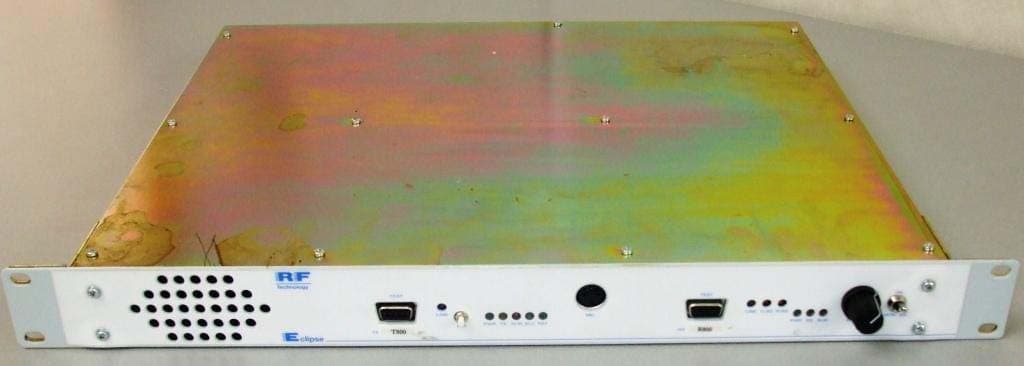
KRE1UTR800CN
Jul 28, 2011UHF BASE STATION
Equipment Class
TNB - Licensed Non-Broadcast Station Transmitter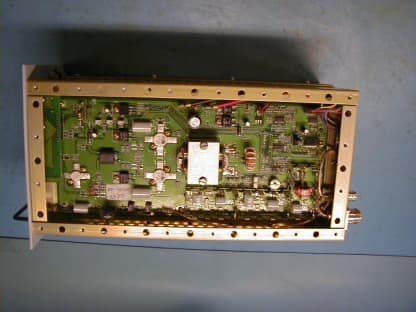
KRE50A
May 08, 200225 - 50 MHz Base Station Transceiver
Equipment Class
TNB - Licensed Non-Broadcast Station Transmitter