KRE-E2-TRX500DUHF BASE STATION
RF Technology Pty Ltd
Click to zoom
Application Details
- Equipment Class
- TNB - Licensed Non-Broadcast Station Transmitter
- Date of Grant
- Apr 09, 2013
- Application Purpose
- Original Equipment
- Date of Application
- Apr 02, 2013
- Equipment Note
- UHF BASE STATION
- Frequency Range
- 470.00000000 - 495.00000000
- Company
- RF Technology Pty Ltd
- Country
- Australia
Documents & Files
Document Text
Text extracted from the exhibit documents filed with the FCC. Open a document above to read the original.
Users Manual
ECLIPSE2 IPCommander User Eclipse2 IP Commander Software User Manual P ublication Reference 23 November 2011 ECLIPSE2 IPCommander User Manual Eclipse2 IP Commander Software User Manual ublication Reference – 0308920019 23 November 2011 1 IP Commander Software ECLIPSE2 IPCommander User Manual 2 Disclaimer Due to our policy of continuous improvement of our products and services, technical specifications and claims that were correct at time going to print maybe subject to variation without notice. RF Technology has endeavoured to ensure that the information in this document is correct, but does not accept liability due to typographical, omissions or other errors or subsequent modifications of the product. Copyright All information contained in this manual is the property of RF Technology Pty Ltd. All rights are reserved. This manual may not, in whole or in part, be copied, photocopied, reproduced, translated, stored, or reduced in any manner without prior written permission. All trade names referenced are the trademarks or registered trademarks of the respective manufacturers. RF Technology Pty Limited Unit 46 / 7 Sefton Road Thornleigh NSW 2120 Sydney Australia Phone +61 2 9484 1022 Fax +61 2 9484 1288 Web www.rftechnology.com.au ECLIPSE2 IPCommander User Manual 3 Contents Contents ............................................................................................................................................ 3 1. Introduction ................................................................................................................................... 6 2. Getting Started .............................................................................................................................. 6 2.1. Connection ............................................................................................................................. 6 2.2. Default Login .......................................................................................................................... 8 2.3. Changing Admin Password ..................................................................................................... 8 2.4. Auto Login .............................................................................................................................. 9 3. Base Station Menu ...................................................................................................................... 10 3.1. Adding a Base Station Connection ....................................................................................... 10 3.2. Connecting to a Base Station ............................................................................................... 11 4. Admin Menu ................................................................................................................................ 12 4.1. Users ..................................................................................................................................... 12 4.2. Base Station Software .......................................................................................................... 13 4.3. Backup and Restore .............................................................................................................. 13 4.3.1. Backup ........................................................................................................................... 14 4.3.2. Restore .......................................................................................................................... 14 4.4. Check for Update .................................................................................................................. 14 4.5. Auto Check Updates ............................................................................................................. 14 4.6. Slow Connection ................................................................................................................... 15 4.7. Play Alarm Audio .................................................................................................................. 15 4.8. Reboot Base Station ............................................................................................................. 15 5. Overview ..................................................................................................................................... 16 5.1. Operational Channel ............................................................................................................ 17 5.2. Networking ........................................................................................................................... 17 5.3. Logging (Syslog) .................................................................................................................... 18 5.4. Versions ................................................................................................................................ 18 5.5. Exciter Transmit Power ........................................................................................................ 18 5.6. Reciter Temperature ............................................................................................................ 18 5.7. RX Path ................................................................................................................................. 18 5.8. RSSI ....................................................................................................................................... 19 5.9. C/N ........................................................................................................................................ 19 5.10. Channel Bandwidth ............................................................................................................ 19 5.11. RX P25 NAC ......................................................................................................................... 19 5.12. RX P25 BER ............…
Text truncated - open the document above for the full version.
Users Manual
Eclipse2 UHF / VHF / 800MHz Base Station Technical Manual 3 August 2012 Eclipse2 Technical Manual, 3-Aug-12 Page 2 of 17 List of Associated Publications Document Nu m b e r Description TPR-0308920019 IP Commander User Manual Disclaimer Due t o our policy of continuous improvement of our products and services, technical specifications and claims that were correct at time going to print maybe subject to variation without notice. RF Technology has endeavoured to ensure that the information in this document is correct, but does not accept liability due to typographical, omissions or other errors or subsequent modifications of the product. Specifications may vary from those given in this document in accordance with the requirements of local regulatory authorities. Copyright All information contained in this manual is the property of RF Technology Pty Ltd. All rights are reserved. This manual may not, in whole or in part, be copied, photocopied, reproduced, translated, stored, or reduced in any manner without prior written permission. All trade names referenced are the trademarks or registered trademarks of the respective manufacturers. Copyright 2009-2012 RF Technology Pty Ltd. Users are cautioned that changes or modifications not expressly approved by RF Technologies could void the user’s authority to operate the equipment. NOTE: This equipment has been tested and found to comply with the limits for a Class B digital device, pursuant to part 15 of the FCC Rules. These limits are designed to provide reasonable protection against harmful interference in a residential installation. This equipment generates, uses and can radiate radio frequency energy and, if not installed and used in accordance with the instructions, may cause harmful interference to radio communications. However, there is no guarantee that interference will not occur in a particular installation. If this equipment does cause harmful interference to radio or television reception, which can be determined by turning the equipment off and on, the user is encouraged to try to correct the interference by one or more of the following measures: -Reorient or relocate the receiving antenna. - Increase the separation between the equipment and receiver. -Connect the equipment into an outlet on a circuit different from that to which the receiver is connected. -Consult the dealer or an experienced radio/TV technician for help. RF Technology Pty Limited Unit 46 / 7 Sefton Road Thornleigh NSW 2120 Sydney Australia Phone +61 2 9484 1022 Fax +61 2 9484 1288 Web www.rftechnology.com.au Eclipse2 Technical Manual, 3-Aug-12 Page 3 of 17 C o nt ents CONTENTS ........................................................................................................... 3 INTRODUCTION ..................................................................................................... 6 FEATURES ........................................................................................................... 6 SPECIFICATIONS .................................................................................................... 6 General ................................................................................................................................................ 6 Receiver ...................................................................................................................................... 6 Exciter ......................................................................................................................................... 7 OPERATION .......................................................................................................... 8 Front Panel Controls and Indicators ............................................................................................ 8 Buttons: ............................................................................................................................................ 8 Indicators: ........................................................................................................................................ 8 Connectors: ...................................................................................................................................... 8 Rear Panel Connectors ............................................................................................................... 8 System I/O: ...................................................................................................................................... 8 4 Wire E&M Port ............................................................................................................................... 9 Ethernet: ........................................................................................................................................ 10 RF input: ........................................................................................................................................ 10 RF output: ...................................................................................................................................... 10 RS232 and external reference clock (optional) ............................................................................... 10 Programming and monitoring .............................................................................................................10 Connecting with Ethernet .......................................................................................................... 11 Connecting with USB ................................................................................................................ 11 Technical Description .........................................................................................................................11 Control Board ............................................................................................................................ 11 Interface (Main) board .........…
Text truncated - open the document above for the full version.
Cover Letter(s)
Date 25 October 2012 Federal Communications Commission Equipment Authorisation Branch 7435 Oakland Mills Road Columbia, MD 21046 United States of America To whom it may concern Re: E2 TRX 500 D The Ecli pse2 UHF Band D Base station/Repeater operates from 470MHz to 495 MHz frequen cy range, the operating frequen cy will be hard coded (pre-programmed) into the unit by the RF Technology using proprietary man ufacturing soft ware at source level which will not be provided to any other party . The IP commander software supplied with the Eclipse2 eq uipment to the dealer/ installer will not be able to alter the frequency range bey ond the range hard coded into the radio by RF Tech nology. The Eclipse 2 radio that is ca pable of ac cepting various digital protocols. We attest that we will ap ply the Declaration of Conformity proced ure to any peripheral portion of any composite filing. We will comply with all requiremen ts of part 90 as required Yours Faithfully Frank Romanin CEO ABN 14 131 764 14 RF Technology Pty Ltd [email protected] Unit 46, Thornleigh Technology Park 7 Sefton Road Thornleigh NSW 2120 T: +61 2 9484 1022 ext 101 F: + 61 2 9484 1822 www.rftechnology.com.au
External Photos
RF TECHNOLOGY PTY LTD. FCC ID: KRE-E2-TRX500D EXTERNAL PHOTOS
Internal Photos
RF TECHNOLOGY PTY LTD. FCC ID: KRE-E2-TRX500D INTERNAL PHOTOS FULL ASSEMBLED ECLIPSE 2 BASE STATION – TOP VIEW CONTROLLER BOARD – TOP VIEW CONTROLLER BOARD – BOTTOM VIEW MAIN BOARD – TOP VIEW – WITH SHIELD MAIN BOARD – BOTTOM VIEW – WITH SHIELD MAIN BOARD – TOP VIEW MAIN BOARD – BOTTOM VIEW TX TOP VIEW WITH FULL SHIELDS COVER TX BOTTOM VIEW WITH FULL SHIELDS COVER TX TOP VIEW WITH SHIELDS TX BOTTOM VIEW WITH SHIELDS TX TOP VIEW TX BOTTOM VIEW RX TOP VIEW WITH FULL SHIELDS COVER RX BOTTOM VIEW WITH FULL SHIELDS COVER RX TOP VIEW WITH SHIELDS RX BOTTOM VIEW WITH SHIELDS RX TOP VIEW RX BOTTOM VIEW
Parts List/Tune Up Info
Procedure for calibrating RF power on Eclipse2 base station 1. Equipments needed: RF communication test equipments and PC to run the program IP commander software. 2. Logon to the base station through IP commander software. 3. To calibrate TX power signal. On the main menu Click on calibrate then select calibrate RF power. On the new pop up window click start. Now type TX power reading in the “Entre measured power” field as you see it in the RF communication test set then click on next. Do the previous operation until a pop up window comes out and said calibration is completed. 4. You should see now that the TX power reading on the RF communication test set is nearly matching the reading of power on the IP commander graphical user interface.
RF Exposure Info
Page 1 of 3 FCC RF Exposure Requirements General information: FCCID: Device category: Fixed as described in Part 2.1091 Environment: Uncontrolled Exposure Fixed devices that operate under Part 90 of this chapter are subject to routine environmental evaluation for RF exposure prior to equipment authorization. Antenna: The manufacturer does not specify an antenna. A typical fix mounted antenna has a gain of 3 dBi. This device has provisions for operation only in fixed locations. Configuration Antenna p/n Type Max. Gain (dBi) fixed Any omni 3 Operating configuration and exposure conditions: The conducted output power is 3 Watts. Although in a typical setting the use qualifies for a duty cycle factor of approximately 50%. The RF exposure calculation will be taken using 100% since in repeater operation the true duty factor can possibly exceed 50%. The manufacturer also markets this device only for occupation use. But, typical installations do not allow for controlled exposure. - A typical fixed installation consists of an antenna system with a coaxial cable of the type RG 213U which has a loss of 1.5 dB for a length of 30 feet at UHF frequencies. MPE Calculation: The minimum separation distance is calculated as follows: The limit for an uncontrolled exposure environment above 300 MHz is determined by the formula S = f/1500 and at 470 MHz is 0.313 mW/cm 2 . Page 2 of 3 Frequency: 470-495 MHz The conducted power output is 3 watts. The coax loss was taken as 0.5 dB. Antenna gain was taken as 3 dBi 100% talk time in 30 minutes Power Density = S= 0.313 mW/cm 2 Page 3 of 3 Conclusion: Using the criteria above to comply with the MPE requirements a safe separation distance of 0.37 m or approximately 1.5 ft is required between the antenna, including any radiating structure, and any persons when normally operated.
Test Report
FCC PART 90 TEST REPORT APPLICANT RF TECHNOLOGY PTY. LTD. ABN 14 131 764 148 Unit 46, Thornleigh Technology Park 7 Sefton Road Thornleigh NEW SOUTH WALES 2120 AUSTRALIA FCC ID KRE-E2-TRX500D MODEL NUMBER TRX500D PRODUCT DESCRIPTION ECLIPSE 2 TRANSCEIVER DATE SAMPLE RECEIVED 9/14/2012 DATE TESTED 9/25/2012 TESTED BY Nam Nguyen APPROVED BY Mario R. de Aranzeta TIMCO REPORT NO. 2413AUT12TestReport.doc TEST RESULTS PASS FAIL THE ATTACHED REPORT SHALL NOT BE REPRODUCED EXCEPT IN FULL WITHOUT THE WRITTEN APPROVAL OF TIMCO ENGINEERING, INC. TABLE OF CONTENTS 849 NW STATE ROAD 45 NEWBERRY, FL 32669 USA PH: 888.472.2424 OR 352.472.5500 FAX: 352.472.2030 EMAIL: [email protected] HTTP://WWW.TIMCOENGR.COM Certificate # 0955-01 Applicant: RF TECHNOLOGY PTY. LTD. FCC ID: KRE-E2-TRX500D Report: R\RFPTYLTD\2413AUT12\2413AUT12TestReport.doc Page 2 of 25 TABLE OF CONTENTS GENERAL REMARKS ........................................................................................................... 3 GENERAL INFORMATION .................................................................................................... 4 TEST PROCEDURES ............................................................................................................ 5 RF POWER OUTPUT ............................................................................................................ 6 MODULATION CHARACTERISTICS ...................................................................................... 7 AUDIO FREQUENCY RESPONSE ......................................................................................... 8 AUDIO LOW PASS FILTER ................................................................................................... 9 AUDIO INPUT VERSUS MODULATION ............................................................................... 10 OCCUPIED BANDWIDTH ................................................................................................... 11 SPURIOUS EMISSIONS AT ANTENNA TERMINALS (CONDUCTED) .................................... 15 FIELD STRENGTH OF SPURIOUS EMISSIONS .................................................................. 18 FREQUENCY STABILITY .................................................................................................... 20 TRANSIENT FREQUENCY BEHAVIOR ................................................................................ 21 EMC EQUIPMENT LIST ...................................................................................................... 25 Applicant: RF TECHNOLOGY PTY. LTD. FCC ID: KRE-E2-TRX500D Report: R\RFPTYLTD\2413AUT12\2413AUT12TestReport.doc Page 3 of 25 GENERAL REMARKS The attached report shall not be reproduced except in full without the written permission of Timco Engineering Inc. The test results relate only to the items tested. Summary The device under test does: fulfill the general approval requirements as identified in this test report not fulfill the general approval requirements as identified in this test report Attestations This equipment has been tested in accordance with the standards identified in this test report. To the best of my knowledge and belief, these tests were performed using the measurement procedures described in this report. All instrumentation and accessories used to test products for compliance to the indicated standards are calibrated regularly in accordance with ISO 17025: 2005 requirements. Testing Certificate # 0955-01 I attest that the necessary measurements were made, under my supervision, at: Timco Engineering Inc. 849 NW State Road 45 Newberry, Fl 32669 Authorized Signatory Name: Mario de Aranzeta C.E.T. Compliance Engineer/ Lab. Supervisor Date: November 1, 2012 Applicant: RF TECHNOLOGY PTY. LTD. FCC ID: KRE-E2-TRX500D Report: R\RFPTYLTD\2413AUT12\2413AUT12TestReport.doc Page 4 of 25 GENERAL INFORMATION DUT Specification DUT Description ECLIPSE 2 TRANSCEIVER FCC ID KRE-E2-TRX500D Model Number TRX500D Serial Number N/A Operating Frequency (470 -495) MHz Test Frequencies 470.0, 482.5, and 495 MHz Type of Emission 11K2F3E Modulation FM DUT Power Source 110–120Vac/50– 60Hz DC Power 12V Battery Operated Exclusively Test Item Prototype Pre-Production Production Type of Equipment Fixed Mobile Portable Test Conditions The temperature was 26ºC Relative humidity of 50%. Modification to the DUT None Test Exercise The DUT was placed in continuous transmit mode. Applicable Standards ANSI/TIA 603-C:2004, FCC CFR 47 Part 90, IC RSS- 119, RSS-GEN Test Facility Timco Engineering Inc. 849 NW State Road 45 Newberry, FL 32669 USA. Applicant: RF TECHNOLOGY PTY. LTD. FCC ID: KRE-E2-TRX500D Report: R\RFPTYLTD\2413AUT12\2413AUT12TestReport.doc Page 5 of 25 TEST PROCEDURES Power Line Conducted Interference: The procedure used was ANSI/TIA 603-C: 2004 using a 50uH LISN. Both lines were observed with the DUT transmitting. The bandwidth of the spectrum analyzer was 10 kHz with an appropriate sweep speed. Bandwidth 20 dB: The measurements were made with the spectrum analyzer's resolution bandwidth (RBW) = 1 MHz and the video bandwidth (VBW) = 3 MHz and the span set as shown on plot. Power Output: The RF power output was measured at the antenna feed point using a peak power meter. Antenna Conducted Emissions: The RBW = 100 kHz, VBW = 300 kHz and the span set to 10.0 MHz and the spectrum was scanned from 30 MHz to the 10 th harmonic of the fundamental. Above 1 GHz the resolution bandwidth was 1 MHz and the VBW = 3 MHz and the span to 50 MHz. Radiation Interference: The test procedure used was ANSI/TIA 603-C:2004 using an Agilent spectrum receiver with pre-selector. The bandwidth (RBW) of the spectrum receiver was 100 kHz up to 1 GHz and 1 MHz above 1 GHz with an appropriate sweep speed. The VBW above 1 GHz was 3 MHz. The analyzer was calibrated in dB above a micro volt at the output of the antenna. Applicant: RF TECHNOLOGY PTY. LTD. FCC ID: KRE-E2-TRX500D Report: R\RFPTYLTD\2413AUT12\2413AUT12TestReport.doc Page 6 of 25 RF POWER OUTPU…
Text truncated - open the document above for the full version.
Contact Information
Applicant
Frank Romanin
Test Firm
Timco Engineering, Inc.Bruno Clavier
Technical Specifications
| # | Rule Parts | Frequency Range | Power Output | Emission | Tolerance |
|---|---|---|---|---|---|
| 4 | 9 | 470 MHz - 495 MHz | 3 W | 8K10F1D | 1055 Hz |
Other Applications from RF Technology Pty Ltd

KRE-E2-IP-PA500AH
Jul 27, 2021ECLIPSE IP POWER AMPLIFIER
Equipment Class
TNB - Licensed Non-Broadcast Station Transmitter
KRE-E2-TRX500B
Dec 30, 2012UHF BASE STATION
Equipment Class
TNB - Licensed Non-Broadcast Station Transmitter
KRE-E2-TRX500A
Dec 30, 2012UHF BASE STATION
Equipment Class
TNB - Licensed Non-Broadcast Station Transmitter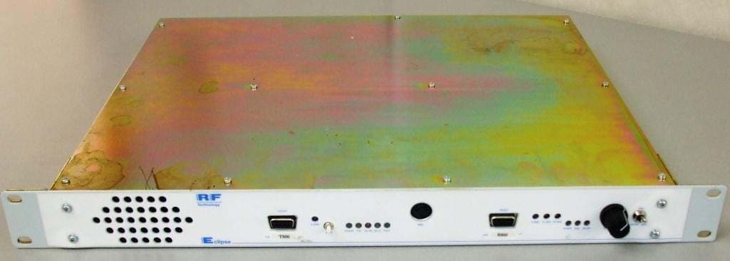
KRE1UTR800CN
Jul 28, 2011UHF BASE STATION
Equipment Class
TNB - Licensed Non-Broadcast Station Transmitter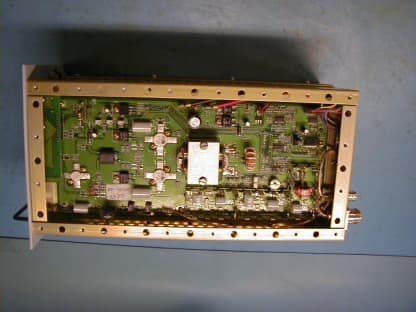
KRE50A
May 08, 200225 - 50 MHz Base Station Transceiver
Equipment Class
TNB - Licensed Non-Broadcast Station Transmitter