KRE200A-ANBase station
RF Technology Pty Ltd
Click to zoom
Application Details
- Equipment Class
- TNB - Licensed Non-Broadcast Station Transmitter
- Date of Grant
- Mar 03, 2002
- Application Purpose
- Original Equipment
- Date of Application
- Nov 17, 2001
- Equipment Note
- Base station
- Frequency Range
- 220.00000000 - 222.00000000
- Company
- RF Technology Pty Ltd
- Country
- Australia
Documents & Files
Document Text
Text extracted from the exhibit documents filed with the FCC. Open a document above to read the original.
Users Manual
Eclipse Series RF Technology [email protected] November 2001 R220 Receiver Operation and Maintenance Manual This manual is produced by RF Technology Pty Ltd., 10/8 Leighton Place, Hornsby, 2077, Australia, and is Copyright ©2001, RF Technology Part No. PCB 30/9132 Page 2RF Technology R220 CONTENTSCONTENTS Contents 1Operating Instructions5 1.1Front Panel Controls and Indicators5 1.1.1Mon. Volume5 1.1.2Mon. Sq.5 1.1.3N. SQ5 1.1.4C. SQ6 1.1.5Line6 1.1.6PWR LED6 1.1.7SQ LED6 1.1.8Alarm LED7 2Receiver Internal Jumper Options7 2.1JP1: 240Hz Notch Filter7 2.2JP2: Audio Response8 2.3JP3: Audio Filter In/Out8 2.4JP4: 600 Ω Line dc Loop COS8 2.5JP6: COS Polarity8 2.6JP7/8/9: dc Loop COS Configuration8 2.7JP7, JP8, JP9: Direct Output COS9 2.8JP11 EPROM Type9 3Receiver I/O Connections11 3.125 Pin Connector11 4Channel and Tone Frequency Programming12 5Circuit Description12 5.1RF Section12 5.2IF Section12 5.3VCO Section13 5.4PLL Section 13 5.5Audio Signal Processing14 5.6Noise Filter, Amplifier and Detector14 5.7Subtone Filter and CTCSS14 5.8External Squelch15 5.9Microprocessor Controller15 5.10 Carrier Operated Switch15 5.11 Voltage Regulator16 6Alignment Procedure16 6.1Standard Input Signal16 6.2RF Alignment16 6.3IF Alignment17 6.4Line Level Adjustment18 6.5Reference Oscillator Calibration18 RF Technology R220Page 3 CONTENTSCONTENTS 7Specifications18 7.1General Description18 7.1.1Channel Capacity18 7.1.2CTCSS18 7.1.3Channel Programming18 7.1.4Channel Selection19 7.1.5Microprocessor19 7.2Physical Configuration19 7.3Front Panel Controls, Indicators and Test Points19 7.3.1Controls19 7.3.2Indicators19 7.3.3Test Points20 7.4Electrical Specifications20 7.4.1Power Requirements20 7.4.2Frequency Range and Channel Spacing20 7.4.3Frequency Synthesizer Step Size20 7.4.4Frequency Stability20 7.4.5Nominal Antenna Impedance20 7.4.6IF Frequencies21 7.4.7Sensitivity21 7.4.8Selectivity21 7.4.9Spurious and Image Rejection21 7.4.10Intermodulation21 7.4.11Modulation Acceptance BW21 7.4.12Noise Squelch21 7.4.13Carrier Level Squelch22 7.4.14Receiver Frequency Spread22 7.4.15Receiver Conducted Spurious Emissions22 7.4.16Audio Frequency Response22 7.4.17Audio Output Level22 7.4.18Audio Distortion22 7.4.19Channel Select Input/Output22 7.4.20Carrier Operated Switch Output23 7.4.21CTCSS23 7.4.22External Squelch Input25 7.5Connectors25 7.5.1Antenna Connector25 7.5.2Power and I/O Connector25 7.5.3Test Connector25 Page 4RF Technology R220 CONTENTSCONTENTS BParts List RF Technology R220Page 5 1OPERATING INSTRUCTIONS WARNING Changes or modifications not expressly approved by RF Technology could void your authority to operate this equipment. Specifications may vary from those given in this document in accordance with requirements of local authorities. RF Technology equipment is subject to continual improvement and RF Technology reserves the right to change performance and specification without further notice. 1 Operating Instructions 1.1 Front Panel Controls and Indicators 1.1.1Mon. Volume The Mon. Volume control is used to adjust the volume of the internal loudspeaker and any external speaker connected to the test socket. It does not effect the level of the 600 Ω line or direct audio output. 1.1.2Mon. SQ. The Mon. SQ. switch allows all squelch functions controlling the monitor output to be disabled. When the switch is in the Mon. SQ. position the audio at the monitor speaker is controlled by the noise detector. The CTCSS, carrier and external squelch functions are disabled. This can be useful when you are trying to trace the source of on-channel interference or when setting the noise squelch threshold. the audio from the 600 Ω line and direct outputs is not effected by the switch position. 1.1.3N.SQ The N.SQ trimpot is used to set the noise squelch sensitivity. Use the following procedure to set the noise squelch to maximum sensitivity. 1.Set the toggle switch to the Mon. Sq. position and set the Mon. Volume control to 9 o’clock. Page 6RF Technology R220 1.1Front Panel Controls and Indicators 1.1 OPERATING INSTRUCTIONS 2. Turn the N. SQ. adjustment counter clockwise until the squelch opens and noise is heard from the speaker. Adjust the VOLUME to a comfortable listening level. 3.In the absence of any on channel signal, turn the N.SQ. screw clockwise until the noise in the speaker is muted. Then turn the screw two additional turns in the clockwise direction. 1.1.4C.SQ The C.SQ trimpot is used to set the carrier squelch sensitivity. Carrier squelch is useful at higher signal levels than those at which noise squelch and can be used typically from 1-200 μ V input. It is provided mainly for use in fixed link applications where a high minimum signal to noise ratio is required or where very fast squelch operation is required for data transmission. The carrier squelch will open and close in less than 2 mSec. In most base station applications carrier squelch is disabled by turning the adjustment counter clockwise until the screw clicks. The carrier squelch may be set to a predetermined level with the Techelp/Service Monitor 2000 software or by using the following procedure: 1. First turn the adjustment fully counter-clockwise. Then set the noise squelch as above. 2. Connect a source of an on channel signal with the desired threshold level to the receiver's RF input. 3. Turn the screw clockwise until the SQ LED goes OFF. Then turn the screw back until the LED just comes ON. 1.1.5LINE The LINE trimpot is used to set the line and direct audio output level. It is normally set to give 0dBm (775mV) to line with a standard input signal equal to 60% of maximum deviation at 1 KHz. The level can be measured between test socket pins 6 and 1 and set as desired. 1.1.6PWR LED The PWR LED shows that the dc supply is connected to the receiver. 1.1.7SQ LED The SQ LED comes on when the audio to the line and direct outputs is un-squelched. RF Technology R220Page 7 2RECEIVER INTERNAL JUMPER OPTIONS The LED and squelch function are controlled by noise,…
Text truncated - open the document above for the full version.
Users Manual
Eclipse Series RF Technology [email protected] November 2001 T220 Transmitter Operation and Maintenance Manual This manual is produced by RF Technology Pty Ltd., 10/8 Leighton Place, Hornsby, 2077, Australia Copyright © 2001, RF Technology Part No. 03/9103/0002 Page 2RF Technology T220 CONTENTS Contents 1Operating Instructions5 1.1Front Panel Controls and Indicators5 1.1.1PTT5 1.1.2Line5 1.1.3PWR LED6 1.1.4TX LED6 1.1.5ALARM LED6 2 Transmitter Internal Jumper Options7 2.1JP2: EPROM type7 2.2JP3: Dc Loop PTT7 2.3JP4: Audio Input Source7 2.4JP6: Input Level Attenuation7 2.5JP7: Audio Response8 2.6JP8: Sub-audible Tone source8 2.7JP9/10/11: dc Loop Configuration8 3Transmitter I/O Connections8 3.125 Pin Connector8 4Channel and Tone Frequency Programming8 5Circuit Description9 5.1VCO Section9 5.2PLL Section10 5.3Power Amplifier10 5.4600 Ω line Input11 5.5Direct Coupled Audio Input11 5.6Local Microphone Input11 5.7CTCSS and Tone Filter11 5.8Audio Signal Processing12 5.9PTT and DC Remote Control12 5.10Microproce ssor Controller13 5.11Voltage Regulator13 6Field Alignment Proceudre13 6.1Standard Test Conditions14 6.2VCO Alignment14 6.3TCXO Calibration14 6.4Modulation Balance15 6.5Tone Deviation15 6.6Deviation16 6.7Line Input Level16 6.8Output Power16 RF Technology T220Page 3 CONTENTS CONTENTS 7Specifications17 7.1Overall Description17 7.1.1Channel Capacity17 7.1.2CTCSS17 7.1.3Channel Programming17 7.1.4Channel Selection17 7.1.5Microprossor18 7.2Physical Configuration18 7.3Front Panel Controls, Indicators and Test Points18 7.3.1Controls18 7.3.2Indicators18 7.3.3Test Points19 7.4Electrical Specifications19 7.4.1Power Requirements19 7.4.2Frequency Range and Channel Spacing19 7.4.3Frequency Synthesizer Step Size19 7.4.4Frequency Stability19 7.4.5Number of Channels19 7.4.6Antenna Impedance19 7.4.7Output Power19 7.4.8Transmit Duty Cycle20 7.4.9Spurious and Harmonics20 7.4.10Carrier and Modulation Attack Time20 7.4.11Modulation20 7.4.12Distortion20 7.4.13Residual Modulation and Noise20 7.4.14600 Ω Line Input Sensitivity20 7.4.15HI-Z Input20 7.4.16Test Microphone Input21 7.4.17External Tone Input21 7.4.18External ALC Input21 7.4.19T/R Relay Driver21 7.4.20Channel Select Input / Output21 7.4.21DC Remote Keying21 7.4.22Programmable No-Tone Period22 7.4.23Firmware Timers22 7.4.24CTCSS22 7.5Connectors22 7.5.1Antenna Connector22 Tone Squelch Frequencies 23 7.5.2Power and I/O Connector24 7.5.3Test Connector24 Page 4RF Technology T220 CONTENTS CONTENTS AEngineering Diagrams24 A.1Block Diagram24 A.2Circuit Diagra ms24 A.3Component Overlay Diagrams25 BParts List RF Technology T220Page 5 1OPERATING INSTRUCTIONS 1 Operating Instructions 1.1 Front Panel Controls and Indicators 1.1.1PTT A front-panel push-to-talk (PTT) button is provided to facilitate bench and field tests and adjustments. The button is a momentary action type. When keyed, audio from the line input is disabled so that a carrier with subtone is transmitted. The front- panel microphone input is not enabled in this mode, but it is enabled when the PTT line on that socket is pulled to ground. 1.1.2Line The LINE trimpot is accessible by means of a small screwdriver from the front panel of the module. It is used to set the correct sensitivity of the line and direct audio inputs. It is factory preset to give 60% of rated deviation with an input of 0dBm (1mW on 600 Ω equivalent to 775mV RMS or about 2.2V peak-to-peak) at 1kHz. The nominal 60% deviation level may be adjusted by measuring between pins 6 and 1 on the test socket, and adjusting the pot. By this means an input sensitivity from approximately -30dBm to +10dBm may be established. An internal jumper provides a coarse adjustment step of 20dB. Between the jumper and the trimpot, a wide range of input levels may be accommodated. WARNING Changes or modifications not expressly approved by RF Technology could void your authority to operate this equipment. Specifications may vary from those given in this document in accordance with requirements of local authorities. RF Technology equipment is subject to continual improvement and RF Technology reserves the right to change performance and specification without further notice. Page 6RF Technology T220 1.1 Front Panel Controls and Indicators 1 OPERATING INSTRUCTIONS LED Flash CadenceFault Condition 5 flashes, pauseSynthesizer unlocked 4 flashes, pauseTuning voltage out of range 3 flashes, pauseLow forward power 2 flashes, pauseHigh reverse (reflected) power 1 flash, pauseLow dc supply voltage LED ON continuouslyTransmitter timed out Table 1: Interpretations of LED flash cadence IndicationFault Condition Flashing, 8 per secondSynthesizer unlocked Flashing, 4 per secondTuning voltage outside correct range Flashing, 2 per secondLow forward power Flashing, 1 per secondHigh reverse power Continuousdc supply voltage low or high Table 2: Interpretations of LED flash speed, for early models 1.1.3PWR LED The PWR LED shows that the dc supply is connected to the receiver. 1.1.4 TX LED The TX LED illuminates when the transmitter is keyed. It will not illuminate (and an ALARM cadence will be shown) if the synthesizer becomes unlocked, or the output amplifier supply is interrupted by the microprocessor. 1.1.5ALARM LED The ALARM LED can indicate several fault conditions if they are detected by the self test program. The alarm indicator shows the highest priority fault present. Receivers using software issue 5 and higher use the cadence of the LED flash sequence to indicate the alarm condition. Refer to table 1. Receivers using software issue 4 and lower use the LED flash rate to indicate the alarm condition. Refer to table 2. RF Technology T220Page 7 2TRANSMITTER INTERNAL JUMPER OPTIONS 2 Transmitter Internal Jumper Options In the following subsections an asterisk (*) signifies the standard (Ex-Factory) configuration of a jumper. 2.1JP2: EPROM Type ConditionPosition 27C2562-3 * 27C641-2 2.2 JP3: Dc Loop PTT This jumper enables or disables the keying of the PTT functi…
Text truncated - open the document above for the full version.
Attestation Statements
EMC Technologies (NZ) Ltd Test Report No 10916 FCC Report date: 15 October 2001 EMC Techno lo gies (NZ) Ltd Telephone: +64 9 360 0862 Fax: +64 9 360 0861 STREET ADDRESS - 47 MacKelvie Street, Grey Lynn, Auckland, New Zealand E-mail: [email protected] POSTAL ADDRESS - PO Box 68 307, Newton, Auckland, New ZealandWeb Site: www.emctech.com.au This report may not be reproduced except in full 6. ATTESTATION This report describes the tests and measurements performed for the purpose of determining compliance with the specification with the following conditions: The test sample was selected by the client. The report relates only to the sample tested. This report does not contain corrections or erasures. Measurement uncertainties with statistical confidence intervals of 95% are shown below test results. Both Class A and Class B uncertainties have been accounted for, as well as influence uncertainties where appropriate. In addition this equipment has been tested in accordance with the requirements contained in the appropriate Commission re gulations. To the best of my knowledge, these tests were performed using measurement procedures that are consistent with industry or Commission standards and demonstrate that the equipment complies with the appropriate standards. I further certify that the necessary measurements were made by EMC Technologies NZ Ltd, 47 MacKelvie Street, Grey Lynn, Auckland, New Zealand. Andrew Cutler General Manager EMC Technologies NZ Ltd
Cover Letter(s)
FCC ID Numbers RF Technologies Pty Ltd have requested that the following FCC ID numbers be associated with the Equipment Authorisation for this product. The product that was tested consisted of three modules which make up the base station repeater. The repeater can be sold as a complete unit and the individual modules can also be sold seperately. Form 731 has been filed for the repeater containing all 3 modules as folows: - Eclipse 200 Series base station repeaterFCC ID: KRE200A-AN The client actually requested KRE200A/AN but the system would only allow a dash. When the evaluation is carried out the client has requested that the following FCC ID’s can also be approved: - Eclipse R220 Receiver Module. FCC ID: KRER200A-AN - Eclipse T200 Exciter Module. FCC ID: KRET200A-AN - Eclipse PA220 Power Amplifier.FCC ID: KREPA220A-AN Andrew Cutler EMC Technologies NZ Ltd
Cover Letter(s)
EMC Technologies (NZ) Ltd Test Report No 10916 FCC Report date: 15 October 2001 EMC Techno lo gies (NZ) Ltd Telephone: +64 9 360 0862 Fax: +64 9 360 0861 STREET ADDRESS - 47 MacKelvie Street, Grey Lynn, Auckland, New Zealand E-mail: [email protected] POSTAL ADDRESS - PO Box 68 307, Newton, Auckland, New ZealandWeb Site: www.emctech.com.au This report may not be reproduced except in full FCC ID: KRE 200A-AN Form 731 ID: EA 159841 To whom it may concern . It seems that the fees that we sent through with this application never made it. I have therefore initiated another Form 159 and have paid by credit card. I hope this expedites this application. I am surprised that the application has gone this far without us being notified of the fees not being sent. Andrew Cutler General Manager EMC Technologies NZ Ltd
Cover Letter(s)
25 th February 2002 FCC ID: KRE200A-AN Form 731:EA159841 Dear Sir / Madam How can I re submit a Form 159. I need to send fees through as the first set of fees did not arrive. How can I do this electronically. Regards Andrew Cutler General Ma na ger EMC Technologies NZ Ltd
External Photos
EMC Technologies (NZ) Ltd Test Report No 10916 FCC Report date: 15 October 2001 EM C Te chnolog ie s (NZ) Lt d Telephone: +64 9 360 0862 Fax: +64 9 360 0861 STREET ADDRESS - 47 MacKelvie Street, Gre y Lynn, Auck la nd, New Zea la ndE- ma il: aucklab@ ihug.co.nz POSTAL ADDRESS - PO Box 68 307, Newton, Auckland, New ZealandWeb Site: www.emctech.com.au T his re po rt may not be re produce d e xce pt i n f ull Overall EMC Technologies (NZ) Ltd Test Report No 10916 FCC Report date: 15 October 2001 EM C Te chnolog ie s (NZ) Lt d Telephone: +64 9 360 0862 Fax: +64 9 360 0861 STREET ADDRESS - 47 MacKelvie Street, Gre y Lynn, Auck la nd, New Zea la ndE- ma il: aucklab@ ihug.co.nz POSTAL ADDRESS - PO Box 68 307, Newton, Auckland, New ZealandWeb Site: www.emctech.com.au T his re po rt may not be re produce d e xce pt i n f ull Power amplifier EMC Technologies (NZ) Ltd Test Report No 10916 FCC Report date: 15 October 2001 EM C Te chnolog ie s (NZ) Lt d Telephone: +64 9 360 0862 Fax: +64 9 360 0861 STREET ADDRESS - 47 MacKelvie Street, Gre y Lynn, Auck la nd, New Zea la ndE- ma il: aucklab@ ihug.co.nz POSTAL ADDRESS - PO Box 68 307, Newton, Auckland, New ZealandWeb Site: www.emctech.com.au T his re po rt may not be re produce d e xce pt i n f ull Exciter EMC Technologies (NZ) Ltd Test Report No 10916 FCC Report date: 15 October 2001 EM C Te chnolog ie s (NZ) Lt d Telephone: +64 9 360 0862 Fax: +64 9 360 0861 STREET ADDRESS - 47 MacKelvie Street, Gre y Lynn, Auck la nd, New Zea la ndE- ma il: aucklab@ ihug.co.nz POSTAL ADDRESS - PO Box 68 307, Newton, Auckland, New ZealandWeb Site: www.emctech.com.au T his re po rt may not be re produce d e xce pt i n f ull Receiver
ID Label/Location Info
EMC Technologies (NZ) Ltd Test Report No 10916 FCC Report date: 15 October 2001 EMC Tec hnol ogi es (NZ) Lt d Telephone: +64 9 360 0862 Fax: +64 9 360 0861 STREET ADDRESS - 47 MacKelvie Street, Grey Lynn, Auckland, New ZealandE-mail: [email protected] POSTAL ADDRESS - PO Box 68 307, Newton, Auckland, New ZealandWeb Site: www.e mcte c h.com.au Thi s re por t m ay not be r eproduc ed e xce pt i n ful l FCC Label positions. Repeater label The FCC label for the Repeater, KRE220A-AN, will be placed at the rear of the rack on a plate that will cover the exposed wiring. EMC Technologies (NZ) Ltd Test Report No 10916 FCC Report date: 15 October 2001 EMC Tec hnol ogi es (NZ) Lt d Telephone: +64 9 360 0862 Fax: +64 9 360 0861 STREET ADDRESS - 47 MacKelvie Street, Grey Lynn, Auckland, New ZealandE-mail: [email protected] POSTAL ADDRESS - PO Box 68 307, Newton, Auckland, New ZealandWeb Site: www.e mcte c h.com.au Thi s re por t m ay not be r eproduc ed e xce pt i n ful l Power amplifier The FCC label for the Power Amplifer, KREPA200A-AN, will replace the current serial number label. EMC Technologies (NZ) Ltd Test Report No 10916 FCC Report date: 15 October 2001 EMC Tec hnol ogi es (NZ) Lt d Telephone: +64 9 360 0862 Fax: +64 9 360 0861 STREET ADDRESS - 47 MacKelvie Street, Grey Lynn, Auckland, New ZealandE-mail: [email protected] POSTAL ADDRESS - PO Box 68 307, Newton, Auckland, New ZealandWeb Site: www.e mcte c h.com.au Thi s re por t m ay not be r eproduc ed e xce pt i n ful l Exciter The FCC label for the Exciter, KRET200A-AN, will replace the current serial number label. EMC Technologies (NZ) Ltd Test Report No 10916 FCC Report date: 15 October 2001 EMC Tec hnol ogi es (NZ) Lt d Telephone: +64 9 360 0862 Fax: +64 9 360 0861 STREET ADDRESS - 47 MacKelvie Street, Grey Lynn, Auckland, New ZealandE-mail: [email protected] POSTAL ADDRESS - PO Box 68 307, Newton, Auckland, New ZealandWeb Site: www.e mcte c h.com.au Thi s re por t m ay not be r eproduc ed e xce pt i n ful l Receiver The FCC label for the Receiver, KRER200A-AN, will replace the current serial number label.
Internal Photos
EMC Technologies (NZ) Ltd Test Report No 10916 FCC Report date: 15 October 2001 EM C Te chnolog ie s (NZ) Lt d Telephone: +64 9 360 0862 Fax: +64 9 360 0861 STREET ADDRESS - 47 MacKelvie Street, Gre y Lynn, Auck la nd, New Zea la ndE- ma il: aucklab@ ihug.co.nz POSTAL ADDRESS - PO Box 68 307, Newton, Auckland, New ZealandWeb Site: www.emctech.com.au T his re po rt may not be re produce d e xce pt i n f ull Power amplifier EMC Technologies (NZ) Ltd Test Report No 10916 FCC Report date: 15 October 2001 EM C Te chnolog ie s (NZ) Lt d Telephone: +64 9 360 0862 Fax: +64 9 360 0861 STREET ADDRESS - 47 MacKelvie Street, Gre y Lynn, Auck la nd, New Zea la ndE- ma il: aucklab@ ihug.co.nz POSTAL ADDRESS - PO Box 68 307, Newton, Auckland, New ZealandWeb Site: www.emctech.com.au T his re po rt may not be re produce d e xce pt i n f ull Exciter EMC Technologies (NZ) Ltd Test Report No 10916 FCC Report date: 15 October 2001 EM C Te chnolog ie s (NZ) Lt d Telephone: +64 9 360 0862 Fax: +64 9 360 0861 STREET ADDRESS - 47 MacKelvie Street, Gre y Lynn, Auck la nd, New Zea la ndE- ma il: aucklab@ ihug.co.nz POSTAL ADDRESS - PO Box 68 307, Newton, Auckland, New ZealandWeb Site: www.emctech.com.au T his re po rt may not be re produce d e xce pt i n f ull Receiver
Internal Photos
EMC Technologies (NZ) Ltd Test Report No 10916 FCC Report date: 15 October 2001 EM C Te chnolog ie s (NZ) Lt d Telephone: +64 9 360 0862 Fax: +64 9 360 0861 STREET ADDRESS - 47 MacKelvie Street, Gre y Lynn, Auck la nd, New Zea la ndE- ma il: aucklab@ ihug.co.nz POSTAL ADDRESS - PO Box 68 307, Newton, Auckland, New ZealandWeb Site: www.emctech.com.au T his re po rt may not be re produce d e xce pt i n f ull Overall EMC Technologies (NZ) Ltd Test Report No 10916 FCC Report date: 15 October 2001 EM C Te chnolog ie s (NZ) Lt d Telephone: +64 9 360 0862 Fax: +64 9 360 0861 STREET ADDRESS - 47 MacKelvie Street, Gre y Lynn, Auck la nd, New Zea la ndE- ma il: aucklab@ ihug.co.nz POSTAL ADDRESS - PO Box 68 307, Newton, Auckland, New ZealandWeb Site: www.emctech.com.au T his re po rt may not be re produce d e xce pt i n f ull Power amplifier EMC Technologies (NZ) Ltd Test Report No 10916 FCC Report date: 15 October 2001 EM C Te chnolog ie s (NZ) Lt d Telephone: +64 9 360 0862 Fax: +64 9 360 0861 STREET ADDRESS - 47 MacKelvie Street, Gre y Lynn, Auck la nd, New Zea la ndE- ma il: aucklab@ ihug.co.nz POSTAL ADDRESS - PO Box 68 307, Newton, Auckland, New ZealandWeb Site: www.emctech.com.au T his re po rt may not be re produce d e xce pt i n f ull Exciter EMC Technologies (NZ) Ltd Test Report No 10916 FCC Report date: 15 October 2001 EM C Te chnolog ie s (NZ) Lt d Telephone: +64 9 360 0862 Fax: +64 9 360 0861 STREET ADDRESS - 47 MacKelvie Street, Gre y Lynn, Auck la nd, New Zea la ndE- ma il: aucklab@ ihug.co.nz POSTAL ADDRESS - PO Box 68 307, Newton, Auckland, New ZealandWeb Site: www.emctech.com.au T his re po rt may not be re produce d e xce pt i n f ull Receiver
Operational Description
Eclipse Series RF Technology [email protected] November, 2001 PA220 Amplifier Operation and Maintenance Manual This manual is produced by RF Technology Pty Ltd 10/8 Leighton Place, Hornsby 2077 Australia Copyright © 2001, RF Technology CONTENTSCONTENTS Contents 1Operating Instructions4 1.1Installation4 1.1.1Sub-rack Wiring Guidelines4 1.2Front Panel Indicators4 1.3Internal Adjustments5 1.4Amplifier I/O Connections5 1.4.1RF Input5 1.4.2RF Output5 1.4.325 Pin Connector6 2Circuit Description6 2.1Amplifiers6 2.2Power Splitter/Combiners7 2.3Directional Coupler7 2.4Low Pass Filter7 2.5Power Control Circuits7 2.6RF Output Indicator8 2.7Over Temperature Protection8 3Field Alignment Procedures8 3.1Output Power Level8 3.2Tuning Procedure9 4Specifications9 4.1Description9 4.2Physical Configuration10 4.3Front Panel Indicators and Test Points10 4.3.1Indicators10 4.3.2Test Points10 4.4Electrical Specifications10 4.4.1Power Requirements10 4.4.2Frequency Range10 4.5Antenna Impedance11 4.6Output Power11 4.6.1Transmit Duty Cycle11 4.7Spurious and Harmonics11 4.8Heatsink Temperature11 4.9ALC Output11 4.10 Connectors11 4.10.1RF Input11 4.10.2RF Output12 4.10.325-Pin Connector12 4.10.49-Pin Connector12 RF Technology PA220 Page 3 CONTENTSCONTENTS AEngineering Diagrams12 A.1Block Diagram12 A.2Circuit Diagra ms12 A.3Component Overlay Diagrams12 BParts List17 B.1PA220 (05/9105/0220)17 Page 4RF Technology PA220 1 OPERATING INSTRUCTIONS 1Operating Instructions The PA220 is part of the Eclipse range of modular base station equipment. It is a power amplifier capable of delivering 100 Watts in the VHF frequency range. It is designed to complement the T220 transmitter, and mounts in a standard Eclipse sub-rack. 1.1 Installation There are no front panel controls. In normal circumstances no alignment or setup is required. If mounted in a sub-rack that has not previously been wired for a power amplifier, the rack connector must be wired according to the guidelines in section 1.1.1 below. 1.1.1Sub-rack Wiring Guidelines When installing an Eclipse Power Amplifier in an Eclipse sub-rack, observe the following guidelines for sub-rack installation: • The sub-rack power supply must be capable of delivering the full current requirements for all modules fitted in the sub-rack, typically 20 Amperes for a 100W transmitter/amplifier. • Owing to the current drain, power supply lines should be cabled to the power amplifier separately and using heavy gauge wire to minimise voltage drop and interference via the power supply of other modules in the rack. • The ALC line from the power amplifier must be connected to the ALC input of the exciter. If this connection is not correctly made, no control of the output power level will be possible. This can result in excessive RF output power, and consequent breach of licensing authority regulations, or possible overload of the unit. With an Eclipse T500, join pin 8 on the exciter and the amplifier. 1.2 Front Panel Indicators PWR LED The power (PWR) LED shows that the dc supply is connected to the transmitter. RFO LED The RF output (RFO) LED indicates that the amplifier is being driven and that the forward output power is above a preset level. This preset indication level is generally set 1 - 3 dB below the preset output power level. The presetting potentiometer RV2 is not accessible without removal of the cover plate. RF Technology PA220 Page 5 1OPERATING INSTRUCTIONS 13. Internal Adjustments TEMP LED The temperature (TEMP) LED indicates illuminates should the amplifier's internal temperature become too high. The RF power is automatically reduced if the internal temperature rises above safe limits. 1.3 Internal Adjustments All internal adjustments are factory set and should not need to be changed under normal conditions. A possible exception to this is the RF output power level which may need to be changed to comply with local licensing requirements. The low forward power warning circuit should be set at the same time as the forward power level. WARNING Ensure that the power setting complies with the requirements of your licensing authority. Failure to do so may result in penalties being imposed by the licensing authority. Output Power The output power is set by RV2. This is nominally set to 100 Watts (+50dBm), but may be set to any value between 20 and 100 Watts depending upon local regulations in the destination country. RV2 determines the threshold affecting the ALC voltage that is fed back to the transmitter module to regulate RF output power. RF Level Detector The forward RF power threshold associated with the RFO LED on the amplifier front panel is set by RV3. This is nominally set at half to three- quarters of the preset output power. 1.4 Amplifier I/O Connections The PA220 has three connectors on the rear panel. 1.4.1RF Input The RF drive is delivered via a BNC connector. The absolute maximum power that should be applied to this connector is 25 Watts. 1.4.2RF Output The RF output signal is available from an N-type connector. Page 6RF Technology PA220 2 CIRCUIT DESCRIPTION PinsFunction 1, 2, 14, 15Positive supply 12, 13, 24, 25Ground (negative supply) 8ALC output Table 1: Pin connections for the 25 pin “D” connector on the rear panel Note: The amplifier is capable of delivering as much as 120 Watts continuously. In certain conditions 1 an RF power of 130 Watts or more can be available via this connector. This corresponds to peak voltages in excess of 100 while currents in excess of 2 Amperes may flow. Appropriate care should be taken when working on the PA220 to avoid making or breaking connections when the amplifier is operating, and to avoid RF burns through close proximity to live connections, etc. 1.4.325 Pin Connector The 25-pin ``D'' connector provides connection to ground and dc power, and from the automatic level control (ALC) circuit. The pin connections are given in table 1. The ALC line floats high to approximately 7Vdc. Pulling this line low will reduce output power. …
Text truncated - open the document above for the full version.
Parts List/Tune Up Info
Eclipse Series RF Technology [email protected] November 2001 T220 Transmitter Operation and Maintenance Manual This manual is produced by RF Technology Pty Ltd., 10/8 Leighton Place, Hornsby, 2077, Australia Copyright © 2001, RF Technology Part No. 03/9103/0002 Page 2RF Technology T220 CONTENTS Contents 1Operating Instructions5 1.1Front Panel Controls and Indicators5 1.1.1PTT5 1.1.2Line5 1.1.3PWR LED6 1.1.4TX LED6 1.1.5ALARM LED6 2 Transmitter Internal Jumper Options7 2.1JP2: EPROM type7 2.2JP3: Dc Loop PTT7 2.3JP4: Audio Input Source7 2.4JP6: Input Level Attenuation7 2.5JP7: Audio Response8 2.6JP8: Sub-audible Tone source8 2.7JP9/10/11: dc Loop Configuration8 3Transmitter I/O Connections8 3.125 Pin Connector8 4Channel and Tone Frequency Programming8 5Circuit Description9 5.1VCO Section9 5.2PLL Section10 5.3Power Amplifier10 5.4600 Ω line Input11 5.5Direct Coupled Audio Input11 5.6Local Microphone Input11 5.7CTCSS and Tone Filter11 5.8Audio Signal Processing12 5.9PTT and DC Remote Control12 5.10Microproce ssor Controller13 5.11Voltage Regulator13 6Field Alignment Proceudre13 6.1Standard Test Conditions14 6.2VCO Alignment14 6.3TCXO Calibration14 6.4Modulation Balance15 6.5Tone Deviation15 6.6Deviation16 6.7Line Input Level16 6.8Output Power16 RF Technology T220Page 3 CONTENTS CONTENTS 7Specifications17 7.1Overall Description17 7.1.1Channel Capacity17 7.1.2CTCSS17 7.1.3Channel Programming17 7.1.4Channel Selection17 7.1.5Microprossor18 7.2Physical Configuration18 7.3Front Panel Controls, Indicators and Test Points18 7.3.1Controls18 7.3.2Indicators18 7.3.3Test Points19 7.4Electrical Specifications19 7.4.1Power Requirements19 7.4.2Frequency Range and Channel Spacing19 7.4.3Frequency Synthesizer Step Size19 7.4.4Frequency Stability19 7.4.5Number of Channels19 7.4.6Antenna Impedance19 7.4.7Output Power19 7.4.8Transmit…
Text truncated - open the document above for the full version.
Contact Information
Applicant
Frank Romanin
Technical Contact
Non-Technical Contact
As above (A B)A B A B
[email protected]0061294765929
Test Firm
EMC Technologies NZ Ltd.Andrew Cutler
Technical Specifications
| # | Rule Parts | Frequency Range | Power Output | Emission | Tolerance |
|---|---|---|---|---|---|
| 1 | 90.210 | 220 MHz - 222 MHz | 110 W | 11K0F3E | 2.5000000000 ppm |
Other Applications from RF Technology Pty Ltd

KRE-E2-IP-PA500AH
Jul 27, 2021ECLIPSE IP POWER AMPLIFIER
Equipment Class
TNB - Licensed Non-Broadcast Station Transmitter
KRE-E2-TRX500D
Apr 09, 2013UHF BASE STATION
Equipment Class
TNB - Licensed Non-Broadcast Station Transmitter
KRE-E2-TRX500B
Dec 30, 2012UHF BASE STATION
Equipment Class
TNB - Licensed Non-Broadcast Station Transmitter
KRE-E2-TRX500A
Dec 30, 2012UHF BASE STATION
Equipment Class
TNB - Licensed Non-Broadcast Station Transmitter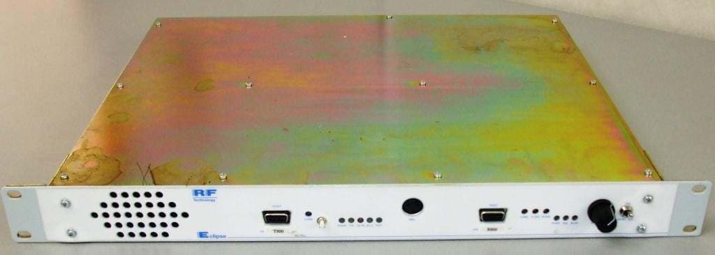
KRE1UTR800CN
Jul 28, 2011UHF BASE STATION
Equipment Class
TNB - Licensed Non-Broadcast Station Transmitter