KUTBR100Remote Transmitter
Capital Prospect Ltd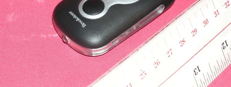
Click to zoom
Application Details
- Equipment Class
- DSC - Part 15 Security/Remote Control Transmitter
- Date of Grant
- Nov 28, 2004
- Application Purpose
- Original Equipment
- Date of Application
- Nov 28, 2004
- Equipment Note
- Remote Transmitter
- Frequency Range
- 389.50000000 - 389.50000000
- Company
- Capital Prospect Ltd
- Country
- Hong Kong
Documents & Files
Document Text
Text extracted from the exhibit documents filed with the FCC. Open a document above to read the original.
Users Manual
1. INTRODUCTION Garage Door Remote Control Model BR-100 Thank you for your purchase of the garage door remote control, Model BR-100. There are 3 different steps you need to set-up in order to use this universal garage door remote control to operate your existing garage door opener. These 3 steps are: 1) Frequency switch – select the correct frequency according to the brand of your existing garage door opener. 2) Brand jumpers – place the brand jumpers at the correct position according to the brand of your existing garage door opener. 3) Code setting – Set the jumper connectors on the Model BR-100 so that they match the code setting of your existing garage door opener. 2. PROGRAMMING YOUR NEW TRANSMITTER 1a. Locate frequency switch on the top of the transmitter. (See diagram A) 1b. Determine the brand of your garage door opener and set the frequency switch to the corresponding position. Diagram A USA CANADA A 390 390 B 318 318 C 310 315 D 300 310 1. SET FREQUENCY SWITCH 2a. To set the brand jumpers, open the case with a coin (see diagram B). 2b. The Model BR-100 contains 2 brand jumpers and 12 code connectors (see diagram C). The brand jumpers are located just above the battery with markings “A” and “B”. There are 2 connectors, one is placed on the “A” column, the other one is placed on the “B” column. For each column, there is a connector. If the connector is placed on the top and middle post of that column, that column is set on “+”. If the connector is placed on the middle and bottom posts, that column is set on “-“. If the connector is removed completely, that column is set on “0” (see diagram C). In order for the Model BR-100 to work with your existing garage door opener (motor), you need to set the brand jumpers based on the brand of your existing garage door opener. Please set these 2 brand jumpers “A” and “B” based on the brand jumpers setting on chart 2. Please identify the group number on chart 2 in order to determine which is the next step to proceed. Diagram B 2. SET BRAND JUMPER Diagram C 3a. If the brand of your garage door opener belongs to groups 4 to 8, that means you need to program the correct code setting in order for the Model BR-100 to work with your existing garage door opener. There are 12 code connectors on 12 columns from 1 to 12 (see diagram E). Each column has one connector. (see diagram F) 3b. Set the connectors numbered 1 through 12 to match the code setting of your existing transmitter or receiver. There are 2 places you can find out the code setting from a column of small switches of your existing garage door opener. 1) your existing transmitter (the unit you currently use to open your garage). 2) the receiver of your garage door opener (the unit with the motor mounted on the ceiling of your garage). 3. SET CODE CONNECTORS Diagram F Diagram E 3c. If the connector is placed on the top and middle posts, that column is set on “ + ” or “ON” or “CLOSE”. If the connector is placed on the middle and bottom posts, that column is set on “ - ” or “OFF” or “OPEN”. If the connector is removed com- pletely, (not placed on any posts), it is set to “ 0 ” or the neutral position. (see diagram G for examples of how to set a column to the three different positions). When removing a connector to set a column to the neutral position, save the connector in case you change the code at a later date. 2. PROGRAMMING YOUR NEW TRANSMITTER (CONT) Diagram G 3d. To move the connectors, slide an opened paperclip into the side of a connector and lift. (see diagram H) When repositioning connectors, place a connector on the two chosen posts, then push down on the connector with your finger. Paper Clip Diagram H 5. WARNING If this transmitter triggers other garage doors in your neighborhood, change all your transmitters and receiver to a new code setting. DO NOT let children use the garage door transmitter without adult supervision. Children can injure themselves or others by the garage door. 3. OPERATION To operate the model BR-100 with your GDO properly, please press the button on the model BR-100. NOTE: Transmission range may be reduced with use on a metal garage door. 4. BATTERY Two 3V Lithium battery (CR2032) included. 6. FCC This device complies with Part 15 of the FCC Rules. Operation is subject to the following two conditions: (1) This device may not cause harmful interference, and (2) This device must accept any interference received, including interference that may cause undesired operation. WARNING: Changes or modifications to this unit not expressly approved by the party responsible for compliance could void the user’s authority to operate the equipment. NOTE: This equipment has been tested and found to comply with the limits for a Class B digital device, pursuant to Part 15 of the FCC Rules. These limits are designed to provide reasonable protection against harmful interference in a residential installation. This equipment generates, uses and can radiate radio frequency energy and, if not installed and used in accordance with the instructions, may cause harmful interference to radio communications. However, there is no guarantee that interference will not occur in a particular installation. If this equipment does cause harmful interference to radio or television reception, which can be determined by turning the equipment off and on, the user is encouraged to try to correct the interference by one or more of the following measures: - Reorient or relocate the receiving antenna. - Increase the separation between the equipment and receiver. - Connect the equipment into an outlet on a circuit different from that to which the receiver is connected. - Consult the dealer or an experienced radio/TV technician for help. BROOKSTONE COMPANY ONE INNOVATION WAY, MERRIMACK, NH 03054 USA 7. WARRANTY If, within one year from date of purchase, this product should become defective (except battery), due to faulty workmanship or materials, it will be repaired or replaced, without charge. Proof of pu…
Text truncated - open the document above for the full version.
External Photos
Test Setup FCC ID : KUTBR100 External Photo – Front External Photo - Rear
Internal Photos
Test Setup FCC ID : KUTBR100 Internal Photo - 1 Internal Photo - 2 Test Setup FCC ID : KUTBR100 Internal Photo - 3
Operational Description
KUTBR100 Confidential Information Aug 16, 2004 TM CAPITAL PROSPECT LTD. TECHNICAL DESCRIPTION MODEL BR-100 REMOTE TRANSMITTER DESCRIPTION The transmitter is a low-power communication device operating at frequency 300, 310, 318 and 389.5 MHz by selecting the "FREQ" switch (SW1). The signal is a digital-coding modulated transmission which transmitted data to a receiver. This digital coding provides different patterns by selecting "CODE" jumpers (J1). FUNCTION The momentary switch (SW3) activates the transmission and the LED (DS1) lights up for indication. The digital modulator is employed in the proprietary integrated circuit (U1), which sends encoded digital data by selection code jumpers. Ceramic Resonator (Y1) and Capacitor (C10, C11) established the clock rate of 4MHz. The oscillator is an LC oscillator formed by transistor (Q1) and associated components. The frequencies of oscillation are controlled by VC 1 or VC2 or VC3 or VC4. The inductive load L3 is configured on the PCB as the principle radiating element which similar to an elementary dipole. Resistor (R2) in conjunction with the base bias circuit (R1) regulates the power output of the transmitter. The LED (DS2) acts the torch by press on the switch (SW2). The unit operates from two CR2032 battery of total 6V. Warning: Changes or modifications to this unit not expressly approved by the party responsible of compliance could void the user's authority to operate the equipment.
Test Report
• The test results reported in this test report shall refer only to the sample actually tested and shall not refer or be deemed to refer to bulk from which such a sample may be said to have been obtained. • This report shall not be reproduced except in full without prior authorization from Intertek Testing Services Hong Kong Limited. • For Terms And Conditions of the services, it can be provided upon request. • The evaluation data of the report will be kept for 3 years from the date of issuance. Intertek Testing Services Hong Kong Ltd. 2/F., Garment Centre, 576 Castle Peak Road, Kowloon, Hong Kong. Tel: (852) 2173 8888 Fax: (852) 2371 0521 Website: www.hk.intertek-etlsemko.com Capital Prospect Ltd. Application For Certification (FCC ID: KUTBR100) Transmitter 0419380 DL/ Sandy Lee November 8, 2004 INTERTEK TESTING SERVICES FCC ID: KUTBR100 i LIST OF EXHIBITS INTRODUCTION EXHIBIT 1: General Description EXHIBIT 2: System Test Configuration EXHIBIT 3: Emission Results EXHIBIT 4: Equipment Photographs EXHIBIT 5: Product Labelling EXHIBIT 6: Technical Specifications EXHIBIT 7: Instruction Manual EXHIBIT 8: Miscellaneous Information INTERTEK TESTING SERVICES FCC ID: KUTBR100 ii MEASUREMENT/TECHNICAL REPORT Capital Prospect Ltd. - MODEL: BROOKSTONE BR-100 FCC ID: KUTBR100 November 8, 2004 This report concerns (check one:) Original Grant X Class II Change Equipment Type: Low Power Transmitter (example: computer, printer, modem, etc.) Deferred grant requested per 47 CFR 0.457(d)(1)(ii)? Yes No X If yes, defer until: date Company Name agrees to notify the Commission by: date of the intended date of announcement of the product so that the grant can be issued on that date. Transition Rules Request per 15.37? Yes No X If no, assumed Part 15, Subpart C for intentional radiator - the new 47 CFR [12-08-03 Edition] provision. Report prepared by: Derek Leung Intertek Testing Services 2/F., Garment Center, 576, Castle Peak Road, Kowloon, Hong Kong. Phone: 852-2173-8539 Fax: 852-2371-0521 INTERTEK TESTING SERVICES FCC ID: KUTBR100 iii Table of Contents 1.0 General Description..............................................................................................2 1.1 Product Description ..............................................................................................2 1.2 Related Submittal(s) Grants .................................................................................2 1.3 Test Methodology.................................................................................................3 1.4 Test Facility ..........................................................................................................3 2.0 System Test Configuration ...................................................................................5 2.1 Justification ..........................................................................................................5 2.2 EUT Exercising Software .....................................................................................5 2.3 Special Accessories .............................................................................................5 2.4 Equipment Modification ........................................................................................6 2.5 Measurement Uncertainty ....................................................................................6 2.6 Support Equipment List and Description ..............................................................6 3.0 Emission Results ..................................................................................................8 3.1 Field Strength Calculation ....................................................................................9 3.2 Radiated Emission Configuration Photograph ....................................................11 3.3 Radiated Emission Data.....................................................................................12 4.0 Equipment Photographs .....................................................................................15 5.0 Product Labelling ................................................................................................17 6.0 Technical Specifications ....................................................................................19 7.0 Instruction Manual ..............................................................................................21 8.0 Miscellaneous Information .................................................................................23 8.1 Measured Bandwidth .........................................................................................24 8.2 Discussion of Pulse Desensitization ...................................................................25 8.3 Calculation of Average Factor ............................................................................26 8.4 Emissions Test Procedures................................................................................27 INTERTEK TESTING SERVICES FCC ID: KUTBR100 iv List of attached file Exhibit type File Description filename Test Report Test Report report.pdf Operation Description Technical Description descri.pdf Test Setup Photo Radiated Emission radiated photos.doc Test Report Bandwidth Plot bw.pdf External Photo External Photo external photos.doc Internal Photo Internal Photo internal photos.doc Block Diagram Block Diagram block.pdf Schematics Circuit Diagram circuit.pdf ID Label/Location Label Artwork and Location label.pdf User Manual User Manual manual.pdf Test Report Timing Diagram timing.pdf INTERTEK TESTING SERVICES FCC ID: KUTBR100 1 EXHIBIT 1 GENERAL DESCRIPTION INTERTEK TESTING SERVICES FCC ID: KUTBR100 2 1.0 General Description 1.1 Product Description The Equipment Under Test (EUT) is a Transmitter operating at 300, 310, 318 and 389.5MHz. The EUT is powered by 6V d.c. (2 x 3V “CR2032” battery). After pressing the key, it transmits control signal to the corresponding receiver. Upon received the control signal by the rec…
Text truncated - open the document above for the full version.
Test Report
Channel A : 389.5 MHz Bandwidth 438 kHz Channel B : 318 MHz Bandwidth 464 kHz Channel C : 310 MHz Bandwidth 479 kHz Channel D : 300 MHz Bandwidth 484 kHz
Test Setup Photos
Test Setup FCC ID : KUTBR100 Radiated Photo – Front Radiated Photo - Rear
Contact Information
Applicant
Joe Ng(Project Manager)
Technical Contact
Intertek Testing Services Hong Kong Ltd.Derek Leung
[email protected]852-2173-8539
2/F., Garment Centre · Kowloon · Hong Kong
Non-Technical Contact
Intertek Testing Services Hong Kong Ltd.Derek Leung
[email protected]852-2173-8539
Test Firm
Intertek Testing Services Hong KongBilly Chow
Technical Specifications
| # | Rule Parts | Frequency Range | Power Output |
|---|---|---|---|
| 4 | 15.231 | 389.5 MHz - 389.5 MHz | - |
Other Applications from Capital Prospect Ltd
KUTSM001
Jun 25, 2023Side Mount Garage Door Opener
Equipment Class
DXX - Part 15 Low Power Communication Device Transmitter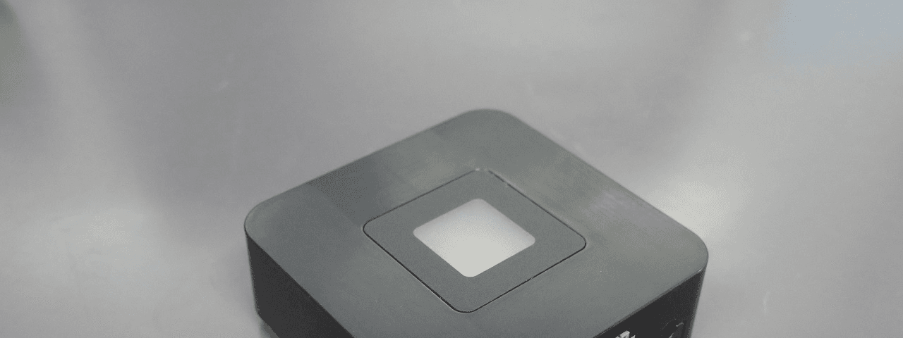
KUT2NV9
Feb 19, 2020Garage Door Controller Mini Nova Hub
Equipment Class
DXT - Part 15 Low Power Transceiver, Rx Verified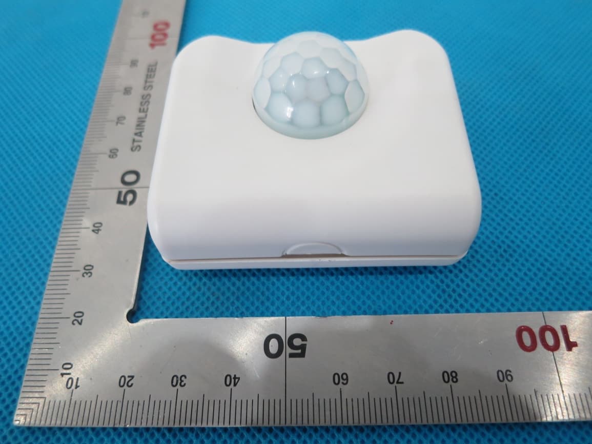
KUTPS10X
Sep 09, 2014Motion Sensor
Equipment Class
DSC - Part 15 Security/Remote Control Transmitter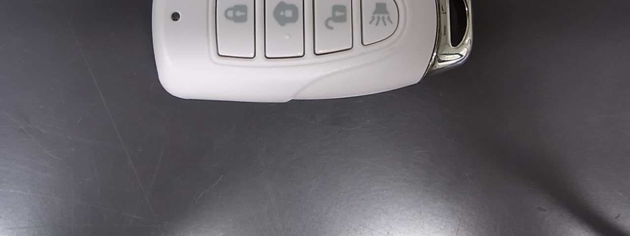
KUTMKA315
Aug 27, 2014315MHz remote control
Equipment Class
DSC - Part 15 Security/Remote Control Transmitter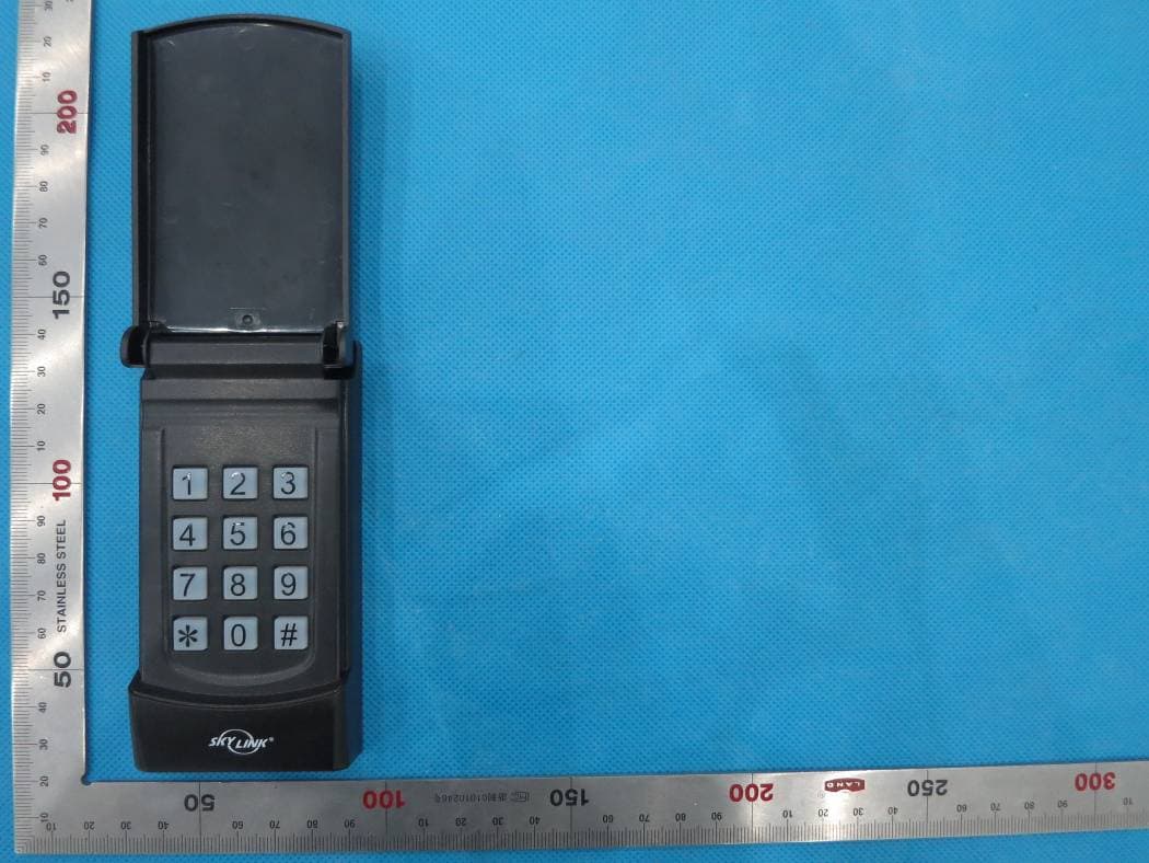
KUTKN103
Jul 16, 2014Wireless keypad
Equipment Class
DSC - Part 15 Security/Remote Control Transmitter