KUTG6T3Remote Control Transmitter
Capital Prospect Ltd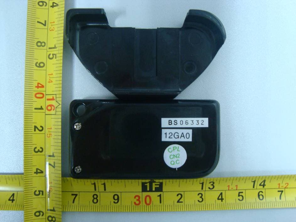
Click to zoom
Application Details
- Equipment Class
- DSC - Part 15 Security/Remote Control Transmitter
- Date of Grant
- May 15, 2011
- Application Purpose
- Original Equipment
- Date of Application
- May 15, 2011
- Equipment Note
- Remote Control Transmitter
- Frequency Range
- 318.00000000 - 318.00000000
- Company
- Capital Prospect Ltd
- Country
- Hong Kong
Documents & Files
Document Text
Text extracted from the exhibit documents filed with the FCC. Open a document above to read the original.
Users Manual
3-Button Garage Door Remote Control Model G6T3 ln this package, you will find a Skylink' garage door transmitter with 3V lithium battery, a mounting bracket, a visor clip and a double sided tape. E lsatteryinsioel A lt-",:l:l"r visorcrio Double Sided Tape There are three buttons on transmitter G6T3, each button can be programed to control Skylink garage door receiver Smad ButtonrM GB-318 or GB-318-3 or Skylink garage door opener directly. Follow one or more instructions below in Section 2 to program transmitter G6T3 to the recetver or receivers you want to control. You need to do the programming in order to add the transmitter - remote control to a receiver. Refer to the receiver Smart Buttonru GB-318 useds instruction to set up the unit. Smart ButtonrM GB-318 can learn up to 10 remote controls. To program the transmitter to the receiver, follow the instructions below: 1. Press the learn button on the side of the Smart ButtonrMGB-319. 2. Once the learn button ts pressed, the LED will llash quickly. Release the learn button. 3. Within 30 seconds, press any one of the 3 buttons on the transmitter that you want to program to the receiver. Once the remote control is programmed, the LED will flash slowly, in the same way as it flashes in standby mode. You may now operate the garage door opener with this new remote control. To program this transmittei.to conirol another receiver. repeat process (1) to (+) to program another button on the remote control. You need to do the programming in order to add the transmitter to a Skylink@ Garage Door Opener. Skylink@ Garage Door Opener can learn up to 16 remote controls. To program the transmttter to the Garage Door Receiver, follow the instructions below: 1. Press the LEARN/SET button once on the garage door opener. 2. Once the LEARN/SET buttton is pressed, the LEARN LED will ftash. You may release the LEARN/SET button. 3. Within 30 seconds, press any one of the 3 buttons on the transmitter that you want to program to the receiver. 4. Once the transmitter is programmed, the LEARN LED will turn off. 5. You may now operate the garage door opener with this new transmitter. 6. To program a transmitter to control another garage door opener, repeat process (1)to (a) to program another button on the transmitter. Smart ButtonrM G8.318 To program the transmitter to a Skylink Garage Door Receiver Smart Buttonru GB-318-3 (3 doors) , please follow the user's instruction for the model GB-g1g-3. To program the transmitter to the Skylinko le senes Garage Door Opener, please follow the user's instruction from the Garage Door Opener. Q: What can I do if the door opener does not react after I press the bufton on the transmitter ? A: - Ensure when the button on the transmitter is pressed, the red light on the transmitter comes on. Otherwise, check if the battery is inserted properly. - Make sure the correct button on the transmitter is pressed. - Ensure the wires that were previously connected to the wall mounted door control are nol loose. - Ensure the transmitter has been programmed to the receiver. Refer to section 2 for how to program a transmitter to the recejver. 3 Volt lithium battery (CR 2032) (inctuded). It is time to change the battery when the red LED on the transrnitter does not turn on when either button is pressed. lf you would like to - find out the up-to-date specifjcations - know more about leatures and applications - download documents, i.e. user's instructions - order Skylink products or iJ you have difficulty getting products to work, please: 1. visit our FAQ section at www.skylinkhome.com, or 2. email us at [email protected], or 3. call ourtoll free at 1-800-304-1187 from Monday to Friday, 9 am to 5 pm EST Fax (800) 286-1320 CUSTOMER SERVICE 17 Sheard Avenue, Brampton, Ontario, Canada L6y 1J3 Email:[email protected] http:i/www.skylinkhome.com P/N.101z,&2 Patent Pending This devicecomplies with Part 15 ofthe Fcc Rules. operation is subjectto thefollowing hryocondttions: (1 ) Thls device may not cause harmfur interference, and (2) Thrs device must accept any interference received, including interference that maycause undesiredoperation. WARNING; changes ormodifrcationsto this unit not expressryapproved bythe party responsibre forcompriance courd void the user's authorilyto operatethe equ pment. NOTE: Thisequipment has beentested and foundto complywiththe rimitsforacrass Bdigitarcrevice, pursuant to Pad 1 5 01 the Fcc Rures These rimits are designed to provide reasonabre protection against harmfur rnterference in a residential installatlon. This equipment generates, uses and can radiate adio frequency energy and, if not installed and used in accordance with the instructions, maycause harmful interference to radio communications However, there is no guarantee that interference will not mur in a particular installation. lf this equipmentdcs cause harmful interferenceto radio orterevision rrception, which can be determined by turning the equipment off and on, the user is encouraged to try to correct the interference byone or more or the foilowing merures: - Reorient or relocate the receiving antenna. - lncrease the separaUon behryeen the equipment and receiver. - Connect the equipment into arl outlet on a circuit different from that to which the receiver ts connected. - Consult the dealer or an experienced radio/Tvtechnician for help. lf, within one year from date of purchase, this product shourd become defective (except battery), due to faulty workmanship or materials, it will be repaired or replaced, without charge. Proof of purchase and a Return Authorization are required. Learn Button o o d lfif, I[!
Cover Letter(s)
CAPITAL PROSPECT LTD. RM I303, BLK B, VERISTRONG IND CENTER,34_36 AUPUIWAN STREET, FOTAN, HONG KONG FCC Confidential Authorization Date: 2011-05-04 FEDERAL COMMUN ICATIONS COMMISSIONS Authorization and Ev aluation Division 7435 Oakland Mills Road Columbia, MD 21046 Confidentiality Request regarding application for ceftificafion of FCC ID: KUTG6T3 Pursuant to Sections 0.457 and 0.459 of the Commission's Rules, we hereby request confidential treatment of information accompanying this application as outlined below: . Detailed Circuit Schematics of EUT--- (Long term) . Block Diagram--- (Long term) . Circuit Description--- (Long term) The above materials contain trade secrets and proprietary information not customarily released to the public. The public disclosure of these materials may be harmful to the applicant and provide unjustified benefits to its competitors. The applicant understands that pursuant to Section 0.457 olthe Rules, disclosure of,this application and all accompanying documentation will not be made before the date of the Grant for this application. Sincerely Yours, -^o Sign*r"tfl' Typed o, vr'fidName: Joe Ng Title: Project Manager
External Photos
EXHIBIT B - EUT EXTERNAL PHOTOGRAPHS EUT– Top View EUT– Bottom View 1 EUT– Bottom View 2
ID Label/Location Info
EXHIBIT A - FCC ID LABELING AND LOCATION FCC ID Label FCC ID Label Location
Internal Photos
EXHIBIT C - EUT INTERNAL PHOTOGRAPHS EUT - Cover off View EUT - Main Board TopView Antenna EUT - Main Board Bottom View
Test Report
Note: This test report is prepared for the customer shown above and for the device described herein. It may not be duplicated or used in part without prior written consent from Bay Area Compliance Laboratories Corp. This report must not be used by the customer to claim product certification, approval, or endorsement by NVLAP*, NIST, or any agency of the Federal Government. * This report contains data that are not covered by the NVLAP accreditation and are marked with an asterisk “★” (Rev.2) FCC PART 15.231 MEASUREMENT AND TEST REPORT For CAPITAL PROSPECT LTD ROOM 1303, BLK B, VERISTRONG IND CENTER, 34-36 AUPUIWAN STREET, FOTAN, HONG KONG FCC ID: KUTG6T3 Report Type: Original Report Product Type: Remote Control Transmitter Test Engineer: Phoenix Liu Report Number: RSZ11030803 Report Date: 2011-05-12 Reviewed By: Merry Zhao EMC Engineer Prepared By: Bay Area Compliance Laboratories Corp. (Shenzhen) 6/F, the 3rd Phase of WanLi Industrial Building, ShiHua Road, FuTian Free Trade Zone Shenzhen, Guangdong, China Tel: +86-755-33320018 Fax: +86-755-33320008 CAPITAL PROSPECT LTD FCC ID: KUTG6T3 Report No.: RSZ11030803 Page 2 of 19 FCC Part15.231 Test Report TABLE OF CONTENTS GENERAL INFORMATION.......................................................................................................................................3 PRODUCT DESCRIPTION FOR EQUIPMENT UNDER TEST (EUT) ....................................................................................3 OBJECTIVE...................................................................................................................................................................3 RELATED SUBMITTAL(S)/GRANT(S).............................................................................................................................3 TEST METHODOLOGY..................................................................................................................................................3 TEST FACILITY.............................................................................................................................................................3 SYSTEM TEST CONFIGURATION ..........................................................................................................................5 JUSTIFICATION.............................................................................................................................................................5 SPECIAL ACCESSORIES.................................................................................................................................................5 EQUIPMENT MODIFICATIONS.......................................................................................................................................5 CONFIGURATION OF TEST SETUP.................................................................................................................................5 BLOCK DIAGRAM OF TEST SETUP................................................................................................................................5 SUMMARY OF TEST RESULTS ...............................................................................................................................6 FCC §15.203 - ANTENNA REQUIREMENT.............................................................................................................7 APPLICABLE STANDARD..............................................................................................................................................7 FCC §15.205, §15.209, §15.35(C) & §15.231(B) - RADIATED EMISSIONS...........................................................8 MEASUREMENT UNCERTAINTY....................................................................................................................................8 EUT SETUP..................................................................................................................................................................8 EMI TEST RECEIVER SETUP.........................................................................................................................................9 TEST PROCEDURE........................................................................................................................................................9 APPLICABLE STANDARD..............................................................................................................................................9 CORRECTED AMPLITUDE & MARGIN CALCULATION...................................................................................................9 TEST EQUIPMENT LIST AND DETAILS.........................................................................................................................10 TEST DATA................................................................................................................................................................10 FCC §15.231(C) – 20 DB BANDWIDTH TESTING ................................................................................................12 REQUIREMENT...........................................................................................................................................................12 TEST EQUIPMENT LIST AND DETAILS.........................................................................................................................12 TEST PROCEDURE......................................................................................................................................................12 TEST DATA................................................................................................................................................................12 FCC §15.231(A) - DEACTIVATION TESTING ......................................................................................................14 REQUIREMENT...........................................................…
Text truncated - open the document above for the full version.
Test Setup Photos
EXHIBIT D - TEST SETUP PHOTOGRAPHS Radiated Emission – Front View (Below 1 GHz) Radiated Emission – Rear View (Below 1 GHz) Radiated Emission – Front View (Above 1 GHz) Radiated Emission – Rear View (Above 1 GHz)
Contact Information
Applicant
Joe Ng(Project Manager)
Test Firm
Bay Area Compliance Laboratory Corp. (Shenzhen)John Chan
Technical Specifications
| # | Rule Parts | Frequency Range | Power Output |
|---|---|---|---|
| 1 | 15.231 | 318 MHz - 318 MHz | - |
Other Applications from Capital Prospect Ltd
KUTSM001
Jun 25, 2023Side Mount Garage Door Opener
Equipment Class
DXX - Part 15 Low Power Communication Device Transmitter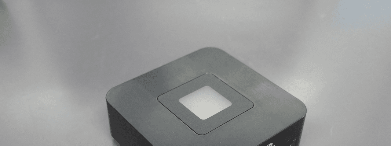
KUT2NV9
Feb 19, 2020Garage Door Controller Mini Nova Hub
Equipment Class
DXT - Part 15 Low Power Transceiver, Rx Verified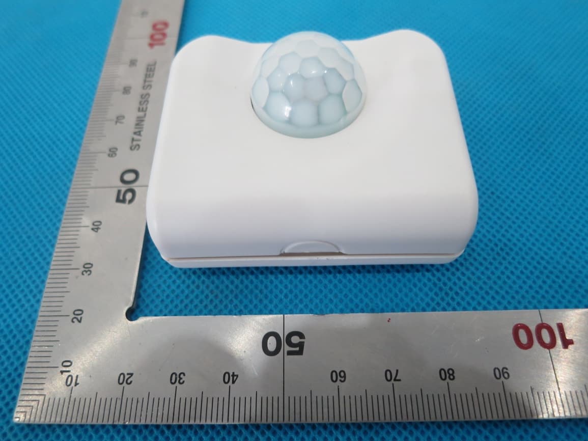
KUTPS10X
Sep 09, 2014Motion Sensor
Equipment Class
DSC - Part 15 Security/Remote Control Transmitter
KUTMKA315
Aug 27, 2014315MHz remote control
Equipment Class
DSC - Part 15 Security/Remote Control Transmitter
KUTKN103
Jul 16, 2014Wireless keypad
Equipment Class
DSC - Part 15 Security/Remote Control Transmitter