KUTGM318TRemote Control (Transmitter)
Capital Prospect Ltd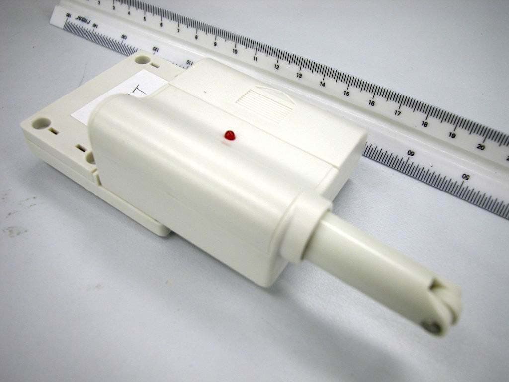
Click to zoom
Application Details
- Equipment Class
- DSC - Part 15 Security/Remote Control Transmitter
- Date of Grant
- Aug 21, 2003
- Application Purpose
- Original Equipment
- Date of Application
- Aug 21, 2003
- Equipment Note
- Remote Control (Transmitter)
- Frequency Range
- 318.00000000 - 318.00000000
- Company
- Capital Prospect Ltd
- Country
- Hong Kong
Documents & Files
Document Text
Text extracted from the exhibit documents filed with the FCC. Open a document above to read the original.
Users Manual
Each receiver can work with up to 4 different sensors (to represent 4 different zones on the receiver), there are 2 connectors that deter- mine the zone number 1, 2, 3, or 4. These 2 connectors can be found by opening the battery cover. Please follow the chart below to set the zone number. If the sensor is set to zone number 1, then the receiver zone 1 signal will correspond to this sensor. 1. INTRODUCTION In order for the sensor to communicate with the receiver properly, the sensor transmission code must match with the receiver’s code. The code setting on the sensor is determined by the code connectors. Code connectors 1 to 6 can be found by opening the battery cover on the sensor and by opening the back cover on the receiver. Note: Before opening the battery cover, it is necessary to remove the transparent protective cover. User is required to set these code connectors randomly and the code settings on the sensor and receiver must be the same. Each position of the code connector can be set to “+”, “-‘ or “0” positions. Refer to the diagram below to set the code connectors properly. If the connector is placed on the top and middle posts, that column is set on “ + ”. If the connector is placed on the middle and bottom posts, that column is set on “ - ”. If the connector is removed completely, (not placed on any posts), it is set to “ 0 ”. (see dia- gram for examples of how to set a column to the three different positions). 2. SET UP THE SENSOR AND RECEIVER Garage Door Monitor Model GM-318 3. POWER UP THE SENSOR AND RECEIVER After setting up all the connectors, both units are ready to be powered up. Plug in the transformer to the receiver, the green LED will start flashing indicating the receiver unit is powered up but no sensor is detected. Remove the battery cover on the sensor and insert the 3V lithium battery to the sensor as shown in the figure. The LED on the sensor will flash 8 times to indicate the unit is properly powered and there is signal transmission to the receiver. The receiver will respond to the transmitted signal depending on the orientation of the sensor. Make sure to put the transparent protective cover pack in place after setting up. If the detection rod on the sensor is fully extended, one of the red LED on the receiver will flash, and the buzzer will also emit beeping to indicate a door is open. If the detection rod is inside the sensor, the green LED on the receiver will glow steadily, indicating the sensor is in a closed position. You can change the orientation of the sensor and you should see the change in response of the receiver. If the sensor and receiver are working properly in close proximity, you can now begin to install the sensor onto your garage door. Note: Ensure you straighten up the antenna on the receiver to receive the best possible reception. 4. INSTALLATION OF THE SENSOR ON YOUR GARAGE DOOR 3V Lithium battery Transformer Receiver Zone number connector Code Connectors on SensorCode Connectors on Receiver Detection rod is inside the sensor Detection rod is fully extended Plug in transformer to the receiverInsert 3V battery to the sensor ‘+’ ‘-’ ‘0’ 1. CODE CONNECTORS 2. ZONE NUMBER Step 1 – Selecting a spot on your garage door to mount the sensor assembly Before you install the sensor assembly onto the garage door, make sure the garage door is closed. The sensor assembly should be mounted on one of the vertical supports of your garage door near the bottom. 4 pcs 3 x 18 screws 1 pc 2 x 5 screw (Include) Sensor The garage door monitor is designed to monitor the status of your garage door and advise you if the door is open. By placing the sensor on the door panel, you will be alerted when the door is open. When the door is open, the sensor will be triggered and transmit a wireless signal to the receiver inside your house. It will then emit a beeping audio signal and the LED indicator will flash. Please follow the instructions below to set up your garage door monitor properly. In this package, you should find a sensor, a receiver, a transformer, 3V lithium battery, user’s manual, and double foam tape accessories. “-“ on the chart means the connector for that position should be removed. “+” on the chart means the connector for that position should be placed on the posts. AB Zone 1++ Zone 2+- Zone 3-+ Zone 4-- One of Ve rtica l Supports Note: If you experience interference from a nearby system, which could accidentally trigger your system, please change the code settings on the sensor and receiver. The code setting on the sensor and receiver should still match after changing the code setting. Double foam tape (Included) Door closedDoor open The sensor is designed to be mounted on the bottom panel of your garage door, so when the door is closed, the detec- tion rod should be inserted inside the sensor. When the door is open, the detection rod will be extended. P ap er C lip / Note: A connector can be removed with a removing tool, as shown. + “+” positive side up After the sensor is installed in place, and receiver is powered up, you may test the operation of both units. Open the garage door and notice the LED flashing on the receiver. If the transmitter is programmed to zone 1, zone 1 LED should flash and the buzzer will emit a single beep continuously. After the door is closed, both the red LED and buzzer will be off, the green LED will glow steadily. If the sensor is programmed to zone 4, zone 4 red LED will flash, and the receiver will emit a continuous “4 beeps”, i.e. “beep beep beep beep” pause “beep beep beep beep” pause ......etc. If you have more than one garage door sensor, the operation will be similar. If 2 sensors are triggered at the same time, both red LED representing 2 zones will flash together, and the buzzer will sound for 2 zones, i.e. if zone 1 and zone 4 are activated, the buzzer will sound: “beep’ pause, “beep beep beep beep”, pause, “beep”, pause, “beep beep beep beep” etc. 5. OPERATION 6. BUZZER VOLUME Instead of disabling the buzze…
Text truncated - open the document above for the full version.
External Photos
Test Setup FCCID : KUTGM318T External Photo -front External Photo - rear
Internal Photos
Test Setup FCC ID : KUTGM318T Internal Photo – 1 Internal Photo - 2
Test Report
E • The test results reported in this test report shall refer only to the sample actually tested and shall not refer or be deemed to refer to bulk from which such a sample may be said to have been obtained. • This report shall not be reproduced except in full without prior authorization from Intertek Testing Services Hong Kong Limited. • For Terms And Conditions of the services, it can be provided upon request. • The evaluation data of the report will be kept for 3 years from the date of issuance. Intertek Testing Services Hong Kong Ltd. 2/F., Garment Centre, 576 Castle Peak Road, Kowloon, Hong Kong. Tel: (852) 2173 8888 Fax: (852) 2371 0521 Website: www.hk.intertek-etlsemko.com Capital Prospect Ltd. Application For Certification (FCC ID: KUTGM318T) Transmitter 0309473 DL/Sandy July 23, 2003 INTERTEK TESTING SERVICES FCC ID: KUTGM318T i LIST OF EXHIBITS INTRODUCTION EXHIBIT 1: General Description EXHIBIT 2: System Test Configuration EXHIBIT 3: Emission Results EXHIBIT 4: Equipment Photographs EXHIBIT 5: Product Labelling EXHIBIT 6: Technical Specifications EXHIBIT 7: Instruction Manual EXHIBIT 8: Miscellaneous Information EXHIBIT 9: Confidentiality Request INTERTEK TESTING SERVICES FCC ID: KUTGM318T ii MEASUREMENT/TECHNICAL REPORT Capital Prospect Ltd. - MODEL: SKYLINK GM318T FCC ID: KUTGM318T July 23, 2003 This report concerns (check one:) Original Grant X Class II Change Equipment Type: Low Power Transmitter (example: computer, printer, modem, etc.) Deferred grant requested per 47 CFR 0.457(d)(1)(ii)? Yes No X If yes, defer until: date Company Name agrees to notify the Commission by: date of the intended date of announcement of the product so that the grant can be issued on that date. Transition Rules Request per 15.37? Yes No X If no, assumed Part 15, Subpart C for intentional radiator - the new 47 CFR [08-20-02 Edition] provision. Report prepared by: Derek Leung Intertek Testing Services 2/F., Garment Center, 576, Castle Peak Road, HONG KONG. Phone: 852-2173-8504 Fax: 852-2371-0521 INTERTEK TESTING SERVICES FCC ID: KUTGM318T iii Table of Contents 1.0 General Description............................................................................................................2 1.1 Product Description ...........................................................................................................2 1.2 Related Submittal(s) Grants...............................................................................................2 1.3 Test Methodology..............................................................................................................3 1.4 Test Facility .......................................................................................................................3 2.0 System Test Configuration .................................................................................................5 2.1 Justification .......................................................................................................................5 2.2 EUT Exercising Software ..................................................................................................5 2.3 Special Accessories...........................................................................................................5 2.4 Equipment Modification ....................................................................................................6 2.5 Measurement Uncertainty..................................................................................................6 2.6 Support Equipment List and Description ...........................................................................6 3.0 Emission Results ..................................................................................................................8 3.1 Field Strength Calculation .................................................................................................9 3.2 Radiated Emission Configuration Photograph .................................................................11 3.3 Radiated Emission Data...................................................................................................12 4.0 Equipment Photographs ...................................................................................................15 5.0 Product Labelling ..............................................................................................................17 6.0 Technical Specifications ....................................................................................................19 7.0 Instruction Manual ...........................................................................................................21 8.0 Miscellaneous Information ...............................................................................................23 8.1 Measured Bandwidth .......................................................................................................24 8.2 Discussion of Pulse Desensitization .................................................................................25 8.3 Calculation of Average Factor .........................................................................................26 8.4 Emissions Test Procedures ..............................................................................................27 9.0 Confidentiality Request ....................................................................................................30 INTERTEK TESTING SERVICES FCC ID: KUTGM318T iv List of attached file Exhibit type File Description filename Test Report Test Report report.pdf Operation Description Technical Description descri.pdf Test Setup Photo Radiated Emission radiated photos.doc Test Report Bandwidth Plot bw.pdf External Photo External Photo external photos.doc Internal Photo Internal Photo internal photos.doc Block Diagram Block Diagram block.pdf Schematics Circuit Diagram circuit.pdf ID Label/Location Label Artwork and Location label.pdf User Manual User Manua…
Text truncated - open the document above for the full version.
Test Setup Photos
Test Setup FCCID : KUTGM318T Radiated -front Radiated - rear
Contact Information
Applicant
Joe Ng(Project Manager)
Technical Contact
Intertek Testing Services Hong Kong Ltd.Derek Leung
[email protected]852-2173-8504
2/F., Garment Centre, · Kowloon, · Hong Kong
Non-Technical Contact
Intertek Testing Services Hong Kong Ltd.Derek Leung
[email protected]852-2173-8504
Test Firm
Intertek Testing Services Hong KongBilly Chow
Technical Specifications
| # | Rule Parts | Frequency Range | Power Output |
|---|---|---|---|
| 1 | 15.231 | 318 MHz - 318 MHz | - |
Other Applications from Capital Prospect Ltd

KUTSM001
Jun 25, 2023Side Mount Garage Door Opener
Equipment Class
DXX - Part 15 Low Power Communication Device Transmitter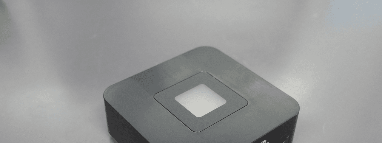
KUT2NV9
Feb 19, 2020Garage Door Controller Mini Nova Hub
Equipment Class
DXT - Part 15 Low Power Transceiver, Rx Verified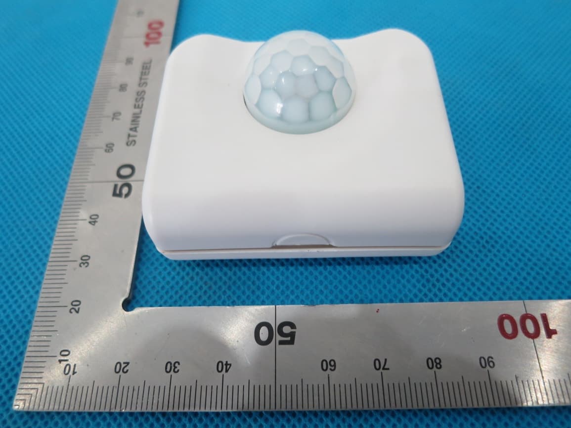
KUTPS10X
Sep 09, 2014Motion Sensor
Equipment Class
DSC - Part 15 Security/Remote Control Transmitter
KUTMKA315
Aug 27, 2014315MHz remote control
Equipment Class
DSC - Part 15 Security/Remote Control Transmitter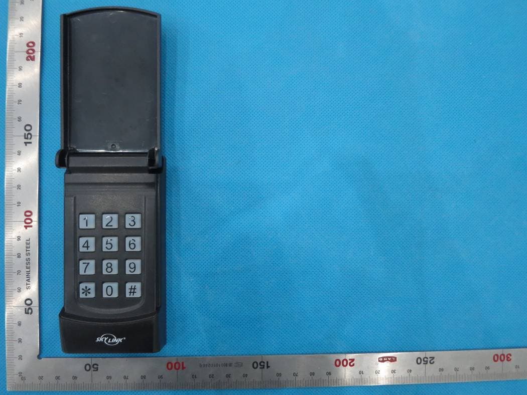
KUTKN103
Jul 16, 2014Wireless keypad
Equipment Class
DSC - Part 15 Security/Remote Control Transmitter