KUTMR318LIGHTING REMOTE CONTROL
Capital Prospect Ltd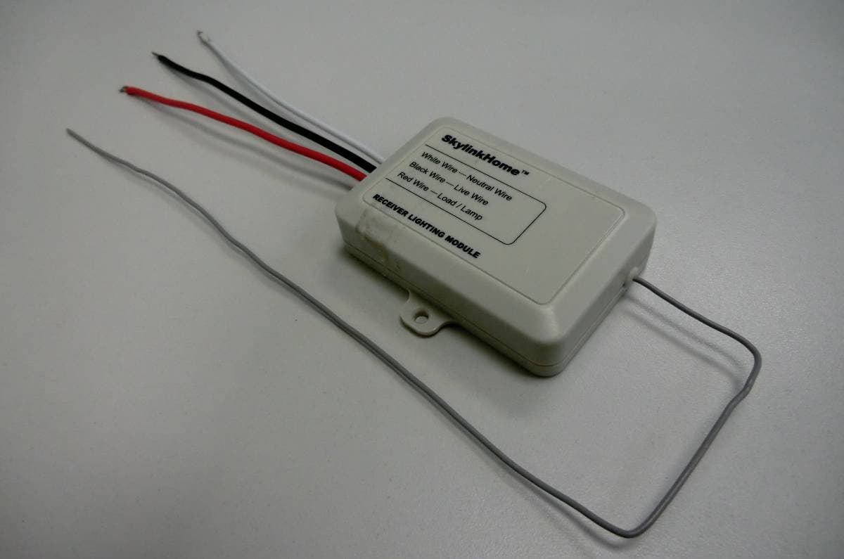
Click to zoom
Application Details
- Equipment Class
- CYY - Communications Receiver used w/Pt 15 Transmitter
- Date of Grant
- Oct 17, 2010
- Application Purpose
- Original Equipment
- Date of Application
- Oct 14, 2010
- Equipment Note
- LIGHTING REMOTE CONTROL
- Frequency Range
- 318.00000000 - 318.00000000
- Company
- Capital Prospect Ltd
- Country
- Hong Kong
Documents & Files
Document Text
Text extracted from the exhibit documents filed with the FCC. Open a document above to read the original.
Users Manual
1. INTRODUCTION On/Off Receiver Module On/Off Receiver Module Model MR-318 Screws and Accessories Thank you for your purchase of a Skylinklighting receiver, On/Off Receiver Module Model MR-318. This On/Off Receiver Module allows you to wirelessly turn on and off different lighting fixtures with the Skylink lighting transmitters. The On/Off Receiver Module MR-318 can communicate with up to8 transmitters, so user has the option to add more transmitters to the system, such as more remote controls, or motion sensors etc. All wireless signal communications within the Skylinklighting system are based on rolling code technology to ensure highest security is used. Screws and Accessories Installation is required and enclosed instructions must befollowed carefully to all steps and notes. If you are uncertain or uncomfortableperforming this installation, please consult a qualified electrician. This manual should also be retained for future reference. Home Home Home The following items are included in this package: On/Off Receiver Module TM TM TM - - CAUTION 2. INSTALLATION Before Installation Live (Usually Black) Load Live (Usually Black) Neutral (Usually White) Neutral (Usually White) (White) (Red) (Black) TM ON OFF Remote Works Remote Does Not Work “PROG” switch Press the desired button 1. Turn off power to the circuit at the circuit breaker of the lighting fixture that you plan on installing the On/Off Receiver Module to. Remove the lighting fixture so the Live and Neutral wires are exposed. WARNING: Failure to turn off power at the circuit breaker can result in electrical shock causing severe or fatal injury. Note: Lighting Load The On/Off Receiver Module is designed to operate maximum load of 900W at 120VAC. Do not connect loading that exceeds this maximum rating. 2. Follow the diagrams below to install the On/Off Receiver Module with the 3 wires: Neutral, Live and Load. Use the provided screws to secure the On/Off Receiver Module. 3. After all the wires are connected, ensure that all of the wire connectors are attached securely and there should be no exposed copper wiring. Straighten the antenna. 4. Secure the MR-318 to a flat surface by 2 screws or you may place it inside the lighting fixture. Install the lighting fixture back to the original configuration. 5. Turn the circuit breaker back on and turn on the wall switch that is used to operate this lighting fixture. 6. The light will be on and you should hear a single beep. The On/Off Receiver Module is installed properly and you can begin programming transmitters to the On/Off Receiver Module. 3. PROGRAMMING TRANSMITTERS In order to operate the On/Off Receiver Module remotely witha transmitter, it must be programmed to the On/Off Receiver Module. Each On/Off Receiver Module can be operated by up to 16 different transmitters (or 16 different command signals). To program a transmitter into the On/Off Receiver Module, follow the instructions below. 1. The On/Off Receiver Module should be power off initially. This can be done by switching off the wall switch or circuit breaker of the lighting fixture. 2. Power on the On/Off Receiver Module by switching on the wall switch. You will hear beeping from the On/Off Receiver Module and the light connected to the module should be on. The beeping indicates the On/Off Receiver Module is now in programming mode and it will stay in this mode for 20 seconds. 3. Press the PROG button on the back of the transmitter with a sharp object. 4. Press the button on the transmitter that you would like to program into the On/Off Receiver Module. 5. Once the transmitter is programmed, the light will be off, indicating you have successfully programmed the transmitter to the On/Off Receiver Module. 6. You may operate the light with the programmed transmitter. You may follow the same instructions to program additional transmitters or sensors to operate the On/Off Receiver Module. or circuit breaker Note: To program other transmitters/sensors (besides TC transmitter), please refer to the instructions of the transmitters/sensors. 4. ON / OFF OPERATION The MR-318 On/Off Receiver Module allows on / off operation, when the programmed button is activate, it will transmit a signal to toggle its current status. For example, if a signal is received when the light is off, that signal will turn on the light. Note: If the On/Off Receiver Module is installed on a ceiling lighting fixture, you can use the transmitter to operate the light remotely only if the wall switch is in the ON position. If the wall switch is off, no power is provided to the On/Off Receiver Module and therefore, it cannot operate the light. In case the transmitter is misplaced, you can still operate the lighting fixture with the wall switch normally. Note: When used with Compact Fluorescent Light, if there is flickering when you switch off the light, it is recommended you replace a different Compact Fluorescent Light with higher quality. On / Off Operation - Original Wall Switch Power On - Light On There is a function "Power On - Light On" built-in to the receiver module. This means when the power supply to the receiver module change from off to on, this will turn the light on. This function allows you to operate the light with original wall switch. When the wall switch is in the off position, switching it on will turn on the light. Once the switch is on, you may use the remote control to operate the light. If the wall switch is switched from on to off, the light will be off. At the same time, the remote control cannot operate the light cause there is no power supplied to the receiver module. After Installation 6. ERASING TC TRANSMITTERS FROM THE ON/OFF RECEIVER MODULE You may erase a TC transmitter from the On/Off Receiver Module, but you cannot erase a specific device, you must erase all the wireless devices, then program the ones you want to keep. Follow the instructions below to erase programmed TC transmitters. 1. Power off the lighting receiver. (Switch off …
Text truncated - open the document above for the full version.
Cover Letter(s)
Rm. 03, 13/F., Block. B, Veristrong Ind. Centre, 34-36 Au Pui Wan Street, Fo Tan, N.T., Hong Kong. Tel: (852) 2602 1318 Fax: (852) 2602 4684 Email: [email protected] I, an officer of Capital Prospect Ltd do hereby authorize Emitel (Mr. Derek Leung) to act on our behalf in front of the Federal Communications Commission with respect to all matters relating to certification of equipment under Part 15 and Part 18 of the FCC Rules until further notice.” I further certify that no party (as defined in & 1.2002 (b) of CFR 47, 1992) to this application, including myself, is subject to a denial of federal benefits, that includes FCC benefits, pursuant to Secretion 5301 of the Anti-Drug Abuse Act of 1988, 21 U.S.C., 853(a). Dated this __26th____day of _July____2010 By _____________________ _Joe Ng __ Signature Printed Title __Project Manager_
ID Label/Location Info
CPL CAPITAL PROSPECT LTD. MODEL : MR-318 LABELING DIAGRAM DATE : SEPT 19, 2010 PAGE : 1 OF 1 REV: A PROPRIETARY INFORMATION LABEL SIZE : 35 X 15MM Model : MR-318 Assembled in China 120 Volts AC 60Hz 600 Watts FOR INDOOR USE ONLY No serviceable parts inside. REMOTE CONTROL X XXX ® Model : MR-318 Assembled in China 120 Volts AC 60Hz 600 Watts FOR INDOOR USE ONLY No serviceable parts inside. REMOTE CONTROL X XXX ® FCC ID : KUTMR318 IC : 4454A-MR318 FCC ID : KUTMR318 IC : 4454A-MR318
Test Report
FCC Test Report E4064136401KY Type / Model Name: MR-318 Brand Name: SKYLINK Product Description: LIGHTING REMOTE CONTROL Applicant: Capital Prospect Limited FCC ID : KUTMR318 File No. E4064136401KY, page 2 of 13 emitel (Shenzhen) Limited, Building 2, 171 Meihua Road, Futian District, Shenzhen, P.R.China 518049 F10_25_Rev5_0 Freigabe: 15.03.2006 FCC -- T E S T R E P O R T Test Report No. : E4064136401KY Oct 09,2010 ______________________________________________________________________________________________ Date of issue Type / Model Name: MR-318 Brand Name : SKYLINK Product Description: LIGHTING REMOTE CONTROL Applicant: Capital Prospect LTD. Address: Room 03, 13/F., Block B, Veristrong Ind. Centre, 34-36 Au Pui Wan Street, Fo Tan, N.T., Hong Kong Test Result according to the standards listed in clause 1 test standards: PASS The test report merely corresponds to the test sample. It is not permitted to copy extracts of these test results without the written permission of the test laboratory. File No. E4064136401KY, page 3 of 13 emitel (Shenzhen) Limited, Building 2, 171 Meihua Road, Futian District, Shenzhen, P.R.China 518049 F10_25_Rev5_0 Freigabe: 15.03.2006 Contents 1 TEST STANDARDS 4 2 SUMMARY 5 3 EQUIPMENT UNDER TEST 6 3.1 PHOTO DOCUMENTATION OF THE EUT 6 3.2 POWER SUPPLY SYSTEM UTILISED 7 3.3 SHORT DESCRIPTION OF THE EQUIPMENT UNDER TEST (EUT) 7 4 TEST ENVIRONMENT 8 4.1 ADDRESS OF THE TEST LABORATORY 8 4.2 ENVIRONMENTAL CONDITIONS 8 4.3 STATEMENT OF THE MEASUREMENT UNCERTAINTY 8 5 TEST CONDITIONS AND RESULTS 9 5.1 RADIATED DISTURBANCE (ELECTRIC FIELD) 9 5.2 CONDUCTED DISTURBANCE 11 6 USED TEST EQUIPMENT AND ACCESSORIES 13 File No. E4064136401KY, page 4 of 13 emitel (Shenzhen) Limited, Building 2, 171 Meihua Road, Futian District, Shenzhen, P.R.China 518049 F10_25_Rev5_0 Freigabe: 15.03.2006 1 TEST STANDARDS The tests were performed according to following standards: FCC Part 15 Subpart B:2008-10-01 Radio frequency devices-Unintentional Radiators ANSI C63.4:2003 Method of Measurement of Radio-Noise Emissions from Low- Voltage Electrical and Electronic Equipment in the Range of 9 kHz to 40 GHz File No. E4064136401KY, page 5 of 13 emitel (Shenzhen) Limited, Building 2, 171 Meihua Road, Futian District, Shenzhen, P.R.China 518049 F10_25_Rev5_0 Freigabe: 15.03.2006 2 SUMMARY GENERAL REMARKS: N/A FINAL ASSESSMENT: The equipment under test fulfils the FCC requirements cited in test standard listed in section 1. Date of receipt of test sample : Jan 07, 2010 Testing commenced on : Jun 10, 2010 Testing concluded on : Oct 09, 2010 Reviewed by: Prepared by: Ivan Toa Technical Manager Kidd Yang Engineer File No. E4064136401KY, page 6 of 13 emitel (Shenzhen) Limited, Building 2, 171 Meihua Road, Futian District, Shenzhen, P.R.China 518049 F10_25_Rev5_0 Freigabe: 15.03.2006 3 EQUIPMENT UNDER TEST 3.1 Photo documentation of the EuT Front View Back View File No. E4064136401KY, page 7 of 13 emitel (Shenzhen) Limited, Building 2, 171 Meihua Road, Futian District, Shenzhen, P.R.China 518049 F10_25_Rev5_0 Freigabe: 15.03.2006 3.2 Power supply system utilised Power supply voltage: AC 120V/60Hz 3.3 Short description of the Equipment under Test (EuT) The EuT is a 318MHz receiver and powered by AC 120V. The radio receiver is designed as a module to receive the signal from the transmitter. When the device receives the signal from the transmitter, It will responds to activate electronic switch. Number of tested samples: One Serial number: Not Labelled Dimensions: L: 6.6cm W: 7.0cm H: 2.0cm EuT operation mode: The equipment under test was operated during the measurement under the following conditions: - Operation mode 1: Maximum load + receiving mode - - EuT configuration: The following interface cables and peripheral devices were connected during the measurements: Interface cables: Interface cable Length Type Line Line termination [m] shieldedunshielded Power cable 1.2 2 wire LISN Power cable 0.8 2 wire To Lamp Peripheral devices: Kind of equipment Model and/or Manufacturer 500W Lamp(120V/60Hz) Philips 100W Lamp(120V/60Hz) Halogen File No. E4064136401KY, page 8 of 13 emitel (Shenzhen) Limited, Building 2, 171 Meihua Road, Futian District, Shenzhen, P.R.China 518049 F10_25_Rev5_0 Freigabe: 15.03.2006 4 TEST ENVIRONMENT 4.1 Address of the test laboratory emitel (Shenzhen) Limited Building 2, 171 Meihua Road, Futian District, Shenzhen, 518049 China FCC Registration No.: 746887 4.2 Environmental conditions During the measurement the environmental conditions were within the listed ranges: Temperature: 15-35 ° C Humidity: 30-60 % Atmospheric pressure: 86-106 kPa 4.3 Statement of the measurement uncertainty The data and results referenced in this document are true and accurate. The reader is cautioned that there may be errors within the calibration limits of the equipment and facilities. The measurement uncertainty was calculated for all measurements listed in this test report acc. to CISPR 16-4-2 /11.2003 „Uncertainties, statistics and limit modelling – Uncertainty in EMC measurements“ and is documented in the quality system acc. to ISO 17025. Furthermore, component and process variability of devices similar to that tested may result in additional deviation. The manufacturer has the sole responsibility of continued compliance of the device. File No. E4064136401KY, page 9 of 13 emitel (Shenzhen) Limited, Building 2, 171 Meihua Road, Futian District, Shenzhen, P.R.China 518049 F10_25_Rev5_0 Freigabe: 15.03.2006 5 TEST CONDITIONS AND RESULTS 5.1 Radiated disturbance (electric field) For test instruments and accessories used see section 6 Part I1. 5.1.1 Description of the test location Test location: Semi-Anechoic Chamber Test distance: 3m 5.1.2 Photo documentation of the test set-up 5.1.3 Test result The test was carried out in the following operation mode(s): - Maximum load + receiving mode Frequency range: 30MHz to 2000MHz Min. limit margin -19.1dB at 636.0MHz. The requirements are FULFILLED Remarks: 1) Acco…
Text truncated - open the document above for the full version.
Contact Information
Applicant
Joe Ng(Project Manager)
Technical Contact
emitel (Shenzhen) LimitedToa Ivan
[email protected]86-0755-8318-2012
Building 2, 171 Meihua Road, Futian District · Shenzhen · China
Test Firm
emitel (Shenzhen) LimitedLouis Lin
Technical Specifications
| # | Rule Parts | Frequency Range | Power Output |
|---|---|---|---|
| 1 | 15B | 318 MHz - 318 MHz | - |
Other Applications from Capital Prospect Ltd

KUTSM001
Jun 25, 2023Side Mount Garage Door Opener
Equipment Class
DXX - Part 15 Low Power Communication Device Transmitter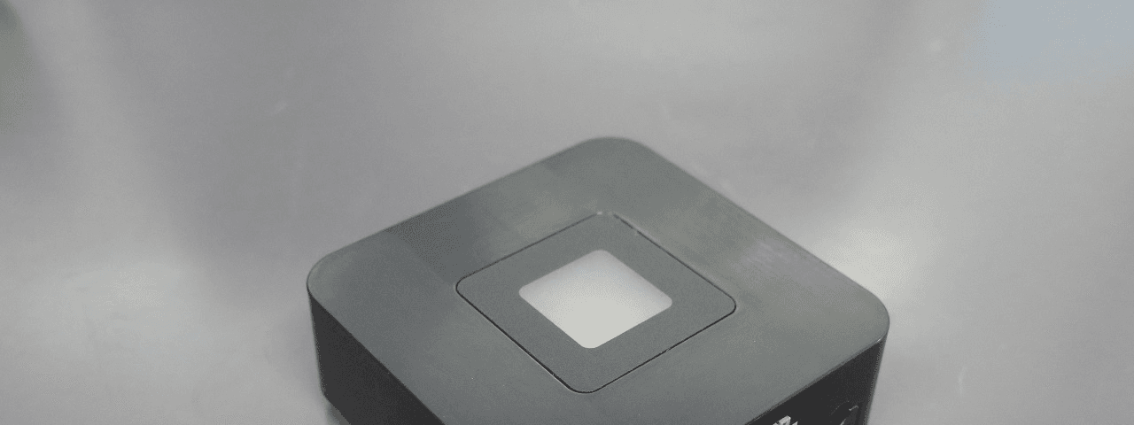
KUT2NV9
Feb 19, 2020Garage Door Controller Mini Nova Hub
Equipment Class
DXT - Part 15 Low Power Transceiver, Rx Verified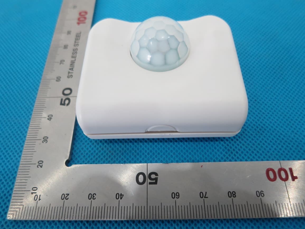
KUTPS10X
Sep 09, 2014Motion Sensor
Equipment Class
DSC - Part 15 Security/Remote Control Transmitter
KUTMKA315
Aug 27, 2014315MHz remote control
Equipment Class
DSC - Part 15 Security/Remote Control Transmitter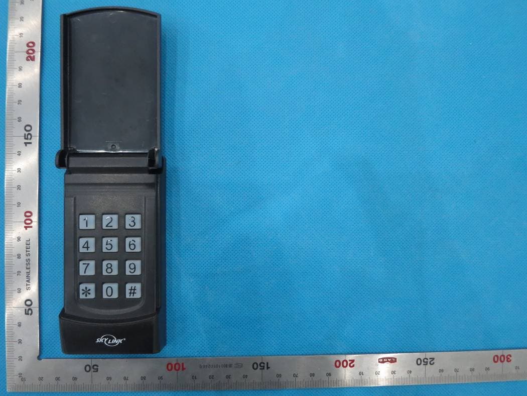
KUTKN103
Jul 16, 2014Wireless keypad
Equipment Class
DSC - Part 15 Security/Remote Control Transmitter