KUTPS434AMotion Alert
Capital Prospect Ltd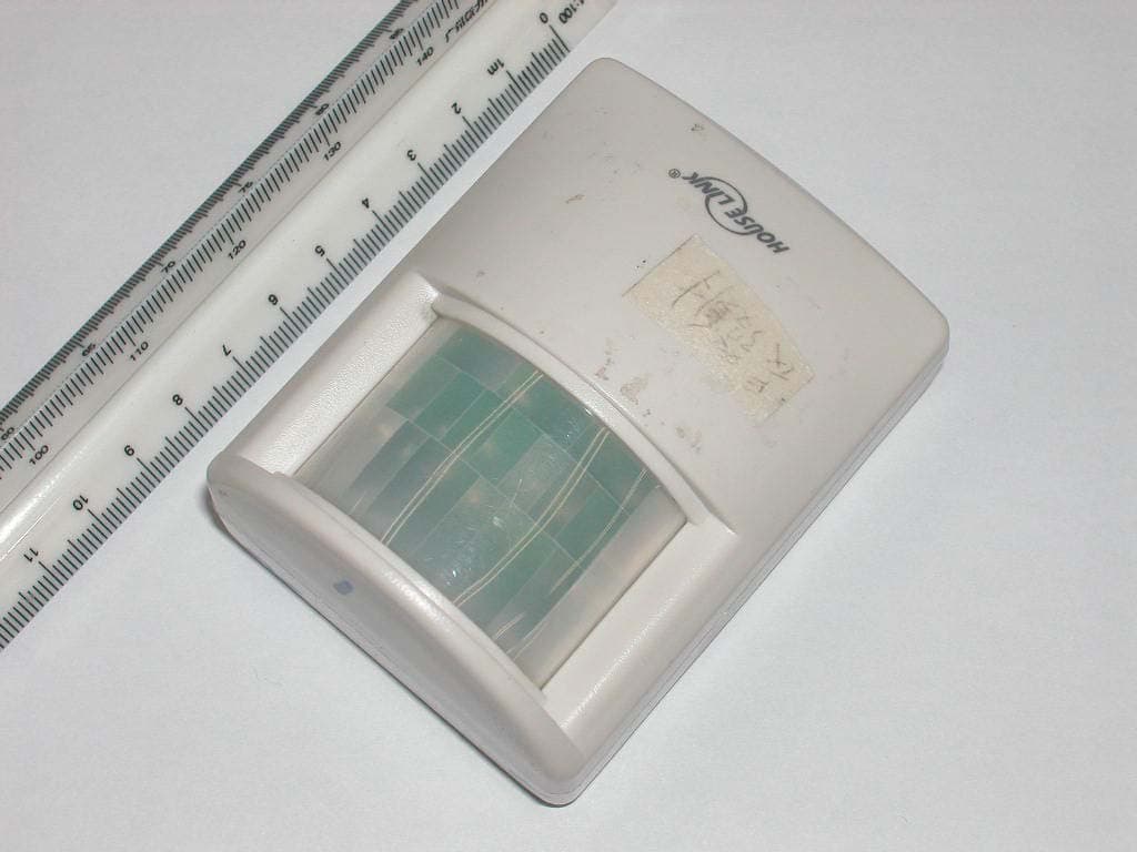
Click to zoom
Application Details
- Equipment Class
- DSC - Part 15 Security/Remote Control Transmitter
- Date of Grant
- Mar 07, 2004
- Application Purpose
- Original Equipment
- Date of Application
- Mar 07, 2004
- Equipment Note
- Motion Alert
- Frequency Range
- 433.90000000 - 433.90000000
- Company
- Capital Prospect Ltd
- Country
- Hong Kong
Documents & Files
Document Text
Text extracted from the exhibit documents filed with the FCC. Open a document above to read the original.
Users Manual
1.Power up the Motion Sensor and wait 45 seconds to warm up. 2.Enter the current MPIN (Master Identification Number) in the Security Control Panel (SC-001) 3.Press [B]. 4.Press the number key to identify which zone to add the Motion Sensor to [1, 2, 3, 4]. We recommend you program the motion sensor to zone 2. The zone light will flash for eight seconds. 5.While the zone light is flashing, press [*]. 6.While the zone light is flashing, walk in front of the Motion Sensor in order to activate it. You will hear a long beep if the motion sensor is “learned” to the control panel. The zone light will stop flashing and the remote sensor will now communicate to that zone. 2. SET UP THE MOTION SENSOR 1. INTRODUCTION Motion Alert Model PS-434A The Motion Alert is designed to monitor movement around your house. The motion sensor can be placed either indoor or outdoor. Once motion is detected, the receiver will beep & flash. In this package, you should find an Indoor/Outdoor Motion Sensor, ball-head joint, screws and a clip. Please follow the instructions below to setup your motion sensor and the receiver. 2 pcs 3 x 18 screws (Included) Indoor/Outdoor Motion Sensor Ball-head joint The sensitivity of the motion sensor is adjustable. Change the setting by placing the connector on either the ”High” or “Low” position. When the sensitivity is set to “Low”, more movement is required to trigger the sensor. It is recommended to set the sensitivity to “Low” and perform a “Walk Test” (Described in Section 3 - “Walk Test”). If the walk test result is satisfied, the sensitivity does not require to be adjusted further. If the walk test result shows the sensitivity is too low, then you can change the sensitivity setting to “High”. Please perform the walk test after changing the sensitivity setting. 2. SENSOR SENSITIVITY Sensitivity Connectors on Motion Sensor A ball-head joint is necessary to mount the sensor at a desire location. A height of 5-6 ft is recommended, depending on your application. Once a location is selected, mount the ball-head joint to this location by screws provided, (see diagram 1). Once the ball-head joint is mounted to the wall, slide the back of the sensor into the ball-head joint (see diagram 2). The mounting angle can be adjusted. Please refer to Section 3 “Walk Test” to determine the best mounting angle. MOUNTING After mounting the sensor at the desired location, it is important to perform a walk test in order to determine if the sensor is detecting the things you want to detect. In order to control how far the sensor can “see”, this can be done by adjusting the angle of the sensor. To reduce the detection range, simply move the sensor downward. To increase the range, move the sensor up to around 12 degrees. This will give the maximum range. However, this may not be desired if the sensor is placed outdoors, since a false trigger may occur if the sensor is set to detect motion in a distance. 4. WALK TEST 1. Program the Motion Sensor to the Security Control Panel (SC-001) 1.Power up the Motion Sensor and wait 45 seconds to warm up. 2.With only the “ON” light lit on the Audio Alarm, press and hold the learn button located on the bottom of the Audio Alarm. 3.While pressing down on the button, activate the Motion Sensor by walking in the monitored area. 4.If a connection has been made, the Audio Alarm will stop beeping and make a continuous tone until the black learn button on the Audio Alarm is released. 5.Now test the sensor by walking in the monitored area. If the Audio Alarm beeps, they are communicating. 2. Program the Motion Sensor to the Audio Alarm (AA-433) 1.Power up the Motion Sensor and wait 45 seconds to warm up. 2.Press [L], [5] when in clock mode, the display will show “L5 Id code”. 3.Activate the Motion Sensor within 5 seconds, the display will return to clock model once the Motion Sensor has been learned. 4.If the Motion Sensor detects any movement, it will trigger the Emergency Dialer and start dialing the preset phone numbers (refer to AD-433S, AD-1010, ED-1010 User’s Instruction). 3. Program the Motion Sensor to the Emergency Dialer (AD-433S, AD-1010, ED-1010) 3. INSTALLING THE MOTION SENSOR You should walk in the area that you would like the sensor to monitor. The receiver will beep if the sensor detects your movement. If the receiver does not respond, adjust the mounting angle accordingly. Perform the walk test again after 30 seconds. Repeat this procedure until your motion is detected. There should be no movement in the detected area during the 30 seconds. Perform walk test in the undesired area to ensure movement cannot be detected. Tips: The sensor should not face towards direct sunlight, placing near heat or cold producing devices (i.e. A/C or furnance vents, fans, ovens, heaters etc.) that may cause false triggers. 12º 4. FCC If, within one year from date of purchase, this product should become defective (except battery), due to faulty workmanship or materials, it will be repaired or replaced, without charge. Proof of purchase and a Return Authorization are required. 5. WARRANTY 6. CUSTOMER SERVICE CUSTOMER SERVICE 2213 Dunwin Drive, Mississauga, Ontario, L5L 1X1, CANADA SKYLINK TECHNOLOGIES-USA 1100 East Valencia Drive, Fullerton, CA 92831 USA TEL (714)224-4321 Email:[email protected] (Reply within 24 hrs) http://www.skylinkhome.com P/N. 101A206-002 Rev.2 ©2003 SKYLINK GROUP If you would like to order Skylink’s products or have difficulty getting them to work, please : 1. visit our FAQ website at www.skylinkhome.com, or 2. email us at [email protected] (reply within 24 hrs), or 3. call our toll free at 1-800-304-1187 from Monday to Friday, 9 am to 5 pm EST. Fax +800 286-1320 Diagram 1 Diagram 2 3. INSTALLING THE MOTION SENSOR (CONT) This device complies with Part 15 of the FCC Rules. Operation is subject to the following two conditions: (1) This device may not cause harmful interference, and (2) This device must accept any interference received, including…
Text truncated - open the document above for the full version.
External Photos
Test Setup FCCID : KUTPS434A External Photo - front External Photo - rear
Internal Photos
Test Setup FCC ID : KUTPS434A Internal Photo - 1 Internal Photo - 2 Test Setup FCC ID : KUTPS434A Internal Photo - 3
Operational Description
ROOM 3, 13/F., BLOCK B, VERISTRONG IND. CENTRE, 34 AUPUIWAN STREET, FOTAN, N.T., HONG KONG. TEL : (852) 2602 5107 FAX: (852) 2602-4684 ps434afcc.doc Confidential Information Jan 15, 2004 3 TECHNICAL DESCRIPTION MODEL PS-434A PIR TRANSMITTER DESCRIPTION The transmitter is a low-power communication device operating at frequency 433.9MHz by SAW device (Y1). The signal is a digital coding modulated transmission, which transmitted data to a receiver. This digital coding provides different patterns by proprietary integrated circuit (U6). FUNCTION The passive infrared detector (FR1) produces a fluctuating voltage of about 1 mV as it detects the heat from a person moving in its fields of view. R32 and C20 and C25 offer some quieting of the power supply noise into the PIR detector as well as some RF filtering. The PIR IC around (U3) forms the amplifier and band pass filter. The output (pin 2) of this IC provides the sufficient swing to latch the proprietary integrated circuit (U6). The integrated circuit (U4) provides the chime alert when detects the low battery power. The digital modulator is employed in the proprietary integrated circuit (U6), which sends encoded digital data. The capacitor (C3 and C17) and ceramic resonator (Y2) established the clock rate of 4MHz. The output data from the proprietary IC (U6) drives a tuned Colpitts power oscillator. A high-Q SAW resonator (Y1) controls frequency of oscillation. The inductive load is configured on the PCB as the principle-radiating element which similar to an elementary dipole. Resistor (R2) in conjunction with the base bias circuit (R1) regulates the power output of the transmitter. The transmitter operates from a 9V battery.
Test Report
• The test results reported in this test report shall refer only to the sample actually tested and shall not refer or be deemed to refer to bulk from which such a sample may be said to have been obtained. • This report shall not be reproduced except in full without prior authorization from Intertek Testing Services Hong Kong Limited. • For Terms And Conditions of the services, it can be provided upon request. • The evaluation data of the report will be kept for 3 years from the date of issuance. Intertek Testing Services Hong Kong Ltd. 2/F., Garment Centre, 576 Castle Peak Road, Kowloon, Hong Kong. Tel: (852) 2173 8888 Fax: (852) 2371 0521 Website: www.hk.intertek-etlsemko.com Capital Prospect Ltd. Application For Certification (FCC ID: KUTPS434A) Transmitter 0401207 DL/ Sandy March 1, 2004 INTERTEK TESTING SERVICES FCC ID: KUTPS434A i LIST OF EXHIBITS INTRODUCTION EXHIBIT 1: General Description EXHIBIT 2: System Test Configuration EXHIBIT 3: Emission Results EXHIBIT 4: Equipment Photographs EXHIBIT 5: Product Labelling EXHIBIT 6: Technical Specifications EXHIBIT 7: Instruction Manual EXHIBIT 8: Miscellaneous Information EXHIBIT 9: Confidentiality Request INTERTEK TESTING SERVICES FCC ID: KUTPS434A ii MEASUREMENT/TECHNICAL REPORT Capital Prospect Ltd. - MODEL: SKYLINK PS-434A FCC ID: KUTPS434A March 1, 2004 This report concerns (check one:) Original Grant X Class II Change Equipment Type: Low Power Transmitter (example: computer, printer, modem, etc.) Deferred grant requested per 47 CFR 0.457(d)(1)(ii)? Yes No X If yes, defer until: date Company Name agrees to notify the Commission by: date of the intended date of announcement of the product so that the grant can be issued on that date. Transition Rules Request per 15.37? Yes No X If no, assumed Part 15, Subpart C for intentional radiator - the new 47 CFR [12-08-03 Edition] provision. Report prepared by: Derek Leung Intertek Testing Services 2/F., Garment Center, 576, Castle Peak Road, HONG KONG. Phone: 852-2173-8504 Fax: 852-2371-0521 INTERTEK TESTING SERVICES FCC ID: KUTPS434A iii Table of Contents 1.0 General Description............................................................................................ 2 1.1 Product Description ............................................................................................ 2 1.2 Related Submittal(s) Grants ............................................................................... 2 1.3 Test Methodology............................................................................................... 3 1.4 Test Facility........................................................................................................ 3 2.0 System Test Configuration ................................................................................. 5 2.1 Justification ........................................................................................................ 5 2.2 EUT Exercising Software.................................................................................... 5 2.3 Special Accessories ........................................................................................... 5 2.4 Equipment Modification ...................................................................................... 6 2.5 Measurement Uncertainty .................................................................................. 6 2.6 Support Equipment List and Description ............................................................. 6 3.0 Emission Results ................................................................................................ 8 3.1 Field Strength Calculation................................................................................... 9 3.2 Radiated Emission Configuration Photograph................................................... 11 3.3 Radiated Emission Data ................................................................................... 12 4.0 Equipment Photographs ................................................................................... 15 5.0 Product Labelling.............................................................................................. 17 6.0 Technical Specifications................................................................................... 19 7.0 Instruction Manual ............................................................................................ 21 8.0 Miscellaneous Information ............................................................................... 23 8.1 Measured Bandwidth........................................................................................ 24 8.2 Discussion of Pulse Desensitization.................................................................. 25 8.3 Calculation of Average Factor........................................................................... 26 8.4 Emissions Test Procedures .............................................................................. 27 9.0 Confidentiality Request.................................................................................... 30 INTERTEK TESTING SERVICES FCC ID: KUTPS434A iv List of attached file Exhibit type File Description filename Test Report Test Report report.pdf Operation Description Technical Description descri.pdf Test Setup Photo Radiated Emission radiated photos.doc Test Report Bandwidth Plot bw.pdf External Photo External Photo external photos.doc Internal Photo Internal Photo internal photos.doc Block Diagram Block Diagram block.pdf Schematics Circuit Diagram circuit.pdf ID Label/Location Label Artwork and Location label.pdf User Manual User Manual manual.pdf Test Report Timing Diagram timing.pdf Cover Letter Confidentiality Request request.pdf INTERTEK TESTING SERVICES FCC ID: KUTPS434A 1 EXHIBIT 1 GENERAL DESCRIPTION INTERTEK TESTING SERVICES FCC ID: KUTPS434A 2 1.0 General Description 1.1 Product Description The Equipment Under Test (EUT) is a transmitter operating at 433.9MHz. The EUT is powered by 9.0V d.c. (1 x 9 …
Text truncated - open the document above for the full version.
Test Setup Photos
Test Setup FCC ID : KUTPS434A Radiated - front Radiated - rear
Contact Information
Applicant
Joe Ng(Project Manager)
Technical Contact
Intertek Testing Services Hong Kong Ltd.Derek Leung
[email protected]852-2173-8504
2/F., Garment Centre, · Kowloon, · Hong Kong
Non-Technical Contact
Intertek Testing Services Hong KongDerek Leung
[email protected]852-2173-8504
Test Firm
Intertek Testing Services Hong KongBilly Chow
Technical Specifications
| # | Rule Parts | Frequency Range | Power Output |
|---|---|---|---|
| 1 | 15.231 | 433.9 MHz - 433.9 MHz | - |
Other Applications from Capital Prospect Ltd

KUTSM001
Jun 25, 2023Side Mount Garage Door Opener
Equipment Class
DXX - Part 15 Low Power Communication Device Transmitter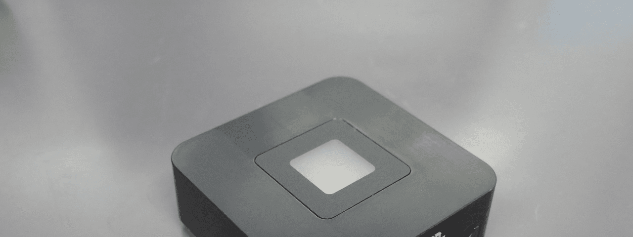
KUT2NV9
Feb 19, 2020Garage Door Controller Mini Nova Hub
Equipment Class
DXT - Part 15 Low Power Transceiver, Rx Verified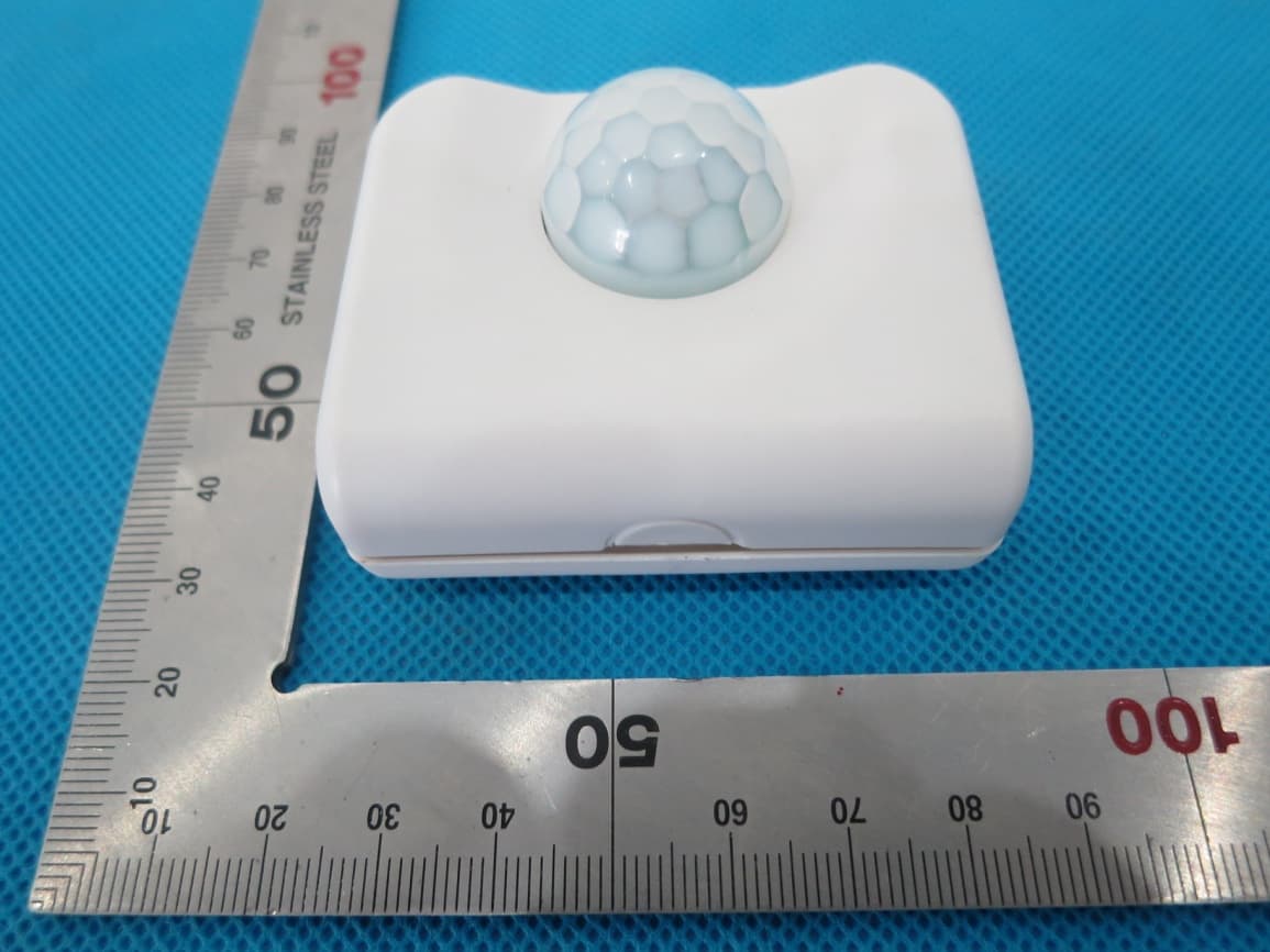
KUTPS10X
Sep 09, 2014Motion Sensor
Equipment Class
DSC - Part 15 Security/Remote Control Transmitter
KUTMKA315
Aug 27, 2014315MHz remote control
Equipment Class
DSC - Part 15 Security/Remote Control Transmitter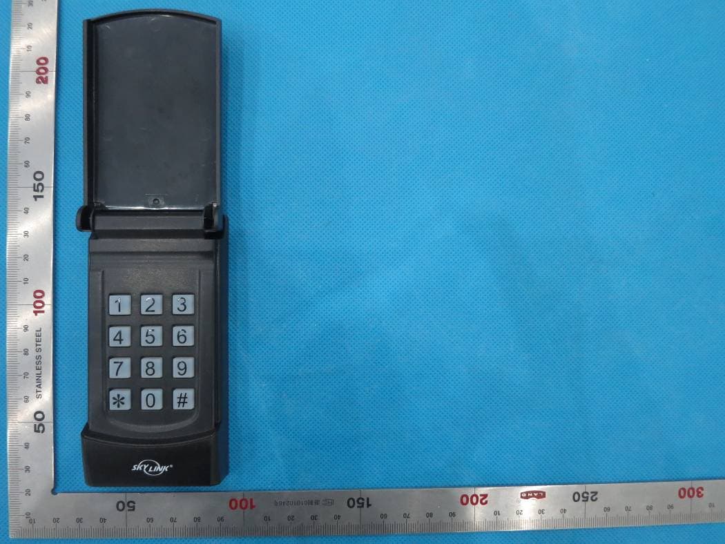
KUTKN103
Jul 16, 2014Wireless keypad
Equipment Class
DSC - Part 15 Security/Remote Control Transmitter