KUTSA001WIRELESS SIREN
Capital Prospect Ltd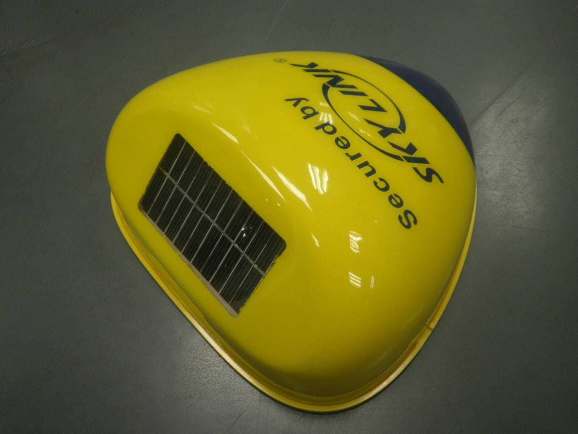
Click to zoom
Application Details
- Equipment Class
- CYY - Communications Receiver used w/Pt 15 Transmitter
- Date of Grant
- Sep 25, 2012
- Application Purpose
- Original Equipment
- Date of Application
- Sep 23, 2012
- Equipment Note
- WIRELESS SIREN
- Frequency Range
- 433.92000000 - 433.92000000
- Company
- Capital Prospect Ltd
- Country
- Hong Kong
Documents & Files
Document Text
Text extracted from the exhibit documents filed with the FCC. Open a document above to read the original.
Users Manual
Wireless External Alarm Model: SA-001A/SA-001S Preliminary Manual 1. Introduction Congratulations on purchasing the Skylink Wireless External Alarm SA-001 Series. The SA-001 Series provide you with a piercing siren and powerful features yet ease to use. You will find the installation to be simple and be able to get the unit up and running easily. The following items are included in this package: - One Wireless External Alarm - AC adapter - Battery (Optional) - User’s Instructions 2. Power Up - Remove the cover of the Wireless External Alarm as shown. - Insert 3 AA batteries or rechargeable batteries (not included) to the unit, its Learn/Set LED will turn on for 1 second and then off. The PWR LED will keep flashing. - Plug in the AC adapter to an AC outlet and the other end into the “DC 12V” jack on the Wireless External Alarm. The PWR LED indication will stay on steadily. 3. Setup – Learn remote or sensors or control panel In order for the remote or sensor or control panel to communicate with the Wireless External Alarm properly, the remote or sensor or control panel must be programmed to the Wireless External Alarm. Follow the brief instructions below to program the remote or sensor or control panel to the Wireless External Alarm. Before proceeding, ensure you have both the Wireless External Alarm and the remote or sensor or control panel next to you. 3A – Learn remote to the Wireless External Alarm: - Press and hold the Learn button on the Wireless External Alarm for 2 seconds and then release. The Learn/Set LED will flash. - Activate the remote by pressing any one of the buttons. - You will hear 2 beeps and the LEDs will flash twice indicating the remote is now programmed to the Wireless External Alarm. 3B – Learn motion sensor to the Wireless External Alarm: - Press and hold the Learn button on the Wireless External Alarm for 2 seconds and then release. The Learn/Set LED will flash. - Activate the motion sensor by pressing the “Test/Set” button on the motion sensor. This “Test/Set” button can usually find inside the battery compartment. - You will hear 2 beeps and the LEDs will flash twice indicating the sensor is now programmed to the Wireless External Alarm. 3C – Learn door/window sensor to the Wireless External Alarm: - Press and hold the Learn button on the Wireless External Alarm for 2 seconds and then release. The Learn/Set LED will flash. - Activate the remote by separating the magnet from the sensor unit. - You will hear 2 beeps and the LEDs will flash twice indicating the sensor is now programmed to the Wireless External Alarm. 3D – Learn control panel to the Wireless External Alarm: - Press and hold the Learn button on the Wireless External Alarm for 2 seconds and then release. The Learn/Set LED will flash. - Activate the control panel by pressing and hold the Mute button on the side of the control panel for 3 seconds. - You will hear 2 beeps and the LEDs will flash twice indicating the control panel is now programmed to the Wireless External Alarm. 4. Setup – Erase remote or sensors or control panel from the Wireless External Alarm To erase unwanted remote(s) or sensor(s) or control panel(s) from the Wireless External Alarm will erase all learned devices from the Wireless External Alarm. - Press and hold the Learn/Set button on the Wireless External Alarm for 5 seconds. All the LEDs will turn on. - While holding the Learn/Set button on the Wireless External Alarm until all the LEDs turn off. You may release the Learn/Set button when the Learn/Set LED stay on. - Press and hold the Learn/Set button on the Wireless External Alarm for 2 seconds until it emits 2 beeps and all the LEDs flash twice. Now you may release the ‘Learn’ button. - All the learned devices have been erased. 5. Setup – Alarm sound duration User can customize the alarm period from 30 seconds up to 10 minutes. The factory default of the alarm period is 30 seconds. - Press and hold the Learn/Set button on the Wireless External Alarm for 5 seconds, you may release the Learn/Set button while all the LEDs turn on. - While the PWR and Learn/Set LED stay on, press the Learn/Set button once on the Wireless External Alarm, the LEDs flash once indicating the alarm period is set to 30 seconds. - If you would set the other alarm period, continue to press the Learn/Set button. Refer to the table below for the alarm period. The LEDs will flash corresponding to the number you pressed the Learn/Set button. 1- 30 seconds 2- 60 seconds 3- 3 minutes 4- 5 minutes 5- 10 minutes - Press and hold the Learn/Set button to confirm your setting. You will hear 2 beeps and the LEDs will flash twice indicating the alarm period is now programmed to the Wireless External Alarm. 6. Setup – Arming Sequence The Wireless External Alarm can be programmed to react 2 arming sequences when it receives the signal from the sensor. In order to arm the Wireless External Alarm, the remote (optional) must be programmed to the Wireless External Alarm. You may arm the Wireless External Alarm in 2 different sequences: 6A – Arm Home Sequence: This setting is used when you wish to secure the area but will be at home and moving around within the armed area. In Arm Home setting, any motion sensor will not respond to any movement. Alarm will sound instantly if any of the sensors (e.g. door/window sensor) is activated (except motion sensor). - Pressing the ARM HOME button on the remote will arm the Wireless External Alarm in Home mode. - You will hear 2 beeps and the LEDs will flash twice indicating the Wireless External Alarm in Home mode. 6B – Arm Away Sequence: This setting is used when you are the last one to leave the premises. By arming the Wireless External Alarm in Away mode, you will have 30 seconds to leave the premises after arming. After 30 seconds, all sensors in the premises are armed. Activating these sensors in Arm Away mode will result in 30 seconds delay. The alarm will sound if not disarm during the 30 seconds period. - Pressing the ARM AWAY …
Text truncated - open the document above for the full version.
Cover Letter(s)
:CPL: CApl.t.AL FROSPI.:C.|. l.'l'fl. Rnr. I,i. 13rF". Block. 8, 1,/eristronE lnd, llentre. 34-38 Au Pu 'r"ian Street. =o Tan. N.T. Hcng Kcng Ts: r8.5li 2882 13:3 Fax i851i260:,168i Enra : cplh<@-ck:ihnkhoft.e.coni Request for Confidentialitv DaIe: _20f2-09-A Subject: Confidentiality Request fbr: KUTSA001 Pursuant to FCC 47 CRF 0.457(d) and 0.459 and IC RSP-100, Section 10, the applicant requests that a part ofthe subject FCC application be held confidential. Type of Confidentiality Requested Exhihit I Short Term I Short Term f Short Term I Short Term f] Short Term f] Short Term I Short Term I Short Term I Short Term X Permanent I Permanent*2 fi Permanent I Permanent n Permanent X Permanent fl Permanent* Block Diagrams External Photos Internal Photos Operation Description/Theory of Operation Parts List & Placement/BOM Tune-Up Procedure Schematics Test Setup Photos User's Manual Joe Ns *Note: (lnsert Explanation as Necessary) Capital Prospect Ltd. has spent substantial effort in developing this product and it is one ofthe first of its kind in industry. Having the subject information easily available to "competition" would negate the advantage they have achieved by developing this product. Not protecting the details of the design will result in financial hardship. Permanent Con{identiality: The applicant requests the exhibits listed above as permanently confidential be permanently withheld from public review due to materials that contain trade secrets and proprietary information not customarily released to the public. Short-Term Confidentiality: The applicant requests the exhibits selected above as short term confidential be withheld from public view for a period of (soecifu number of dry )3- days fiom the date of the Grant of Equipment Authorization and prior to marketing. This is to avoid premature release of sensitive infbrmation prior to marketing or release of the product to the public. Applicant is also aware that they are responsible to notif ACB in the event information regarding the product or the product is made available to the public. ACB will then release the documents listed above for public disclosure pursuant to FCC Public Notice DA 04-1705. NOTE for Industry Canada Applications: The applicant understands that until such time that lC distinguishes between Short Term and Permanent Confidentiality, either type of marked exhibit above will simply be marked Confidential when submitted to IC. Sincerely, By: (Print name) 2 - The asterisked items (*) require further justification before permanent confidentiality will be allowed. These also currently require review by the FCC under their Permit-But-Ask policy before the grant is issued and can delay completion of an application. Furtherjustification should be added to the note above. One such example for a potted device would be: "The EUT is FULLY potted using a non-removable epoxy based material. Removal of potting material causes irreparable , damage to internal circuitry. See photographs exhibits fhat oufline the device before and after potting." details. 4_ 022311 -6
Cover Letter(s)
=CPL: Rnr. 01. 13rF., Slcck. 8 Kurg Te : il.52i 2E0l cAlll'l'A L PRosIr!:c'l' L'l'f). ,.renst-cng lnd- Centre 3.{-3E.A.u Pu /..'an Street. ;r: Tan, H.T . Hurg 13rE Far iB52i.2tl,l2,i68i Enra : cplhr@sk.;linkhcn'e.cc,nr Authority to Act as Aeent Date: , 2012-09-17 American Certification Body, lnc. 6731 Whittier Avenue Suite C1l0 Mclean, VA 22101 To Whom It May Concern: emitel(Shenzhen) limitedis authorized to act on our behalf, until otherwise notified, for applications to American Certification Body, lnc. (ACB). We certify that we are not subject to denial of federal benefits, that includes FCC benefits, pursuant to Section 5301 of the Anti-Drug Abuse Act of 1988, 21 U.S.C. 862. Further, no party, as defined in 47 CFR 1.2002 (b) to the application is subject to denial of federal benefits, that includes FCC benefits. Thank you, Agency Agreement Expiration Date: (Typicallv 8 - 12 months) By: Title: On behalf of: Joe Ns (Print name) tr. _ Project Manag,er Caoital Prosoect Ltd. (Company Name) Telephone: (!52)26021313 t_ 022311 -6
External Photos
SA-001A SA-001S
ID Label/Location Info
CPL CAPITAL PROSPECT LTD. MODEL : SA-001A/SA-001S LABEL DIAGRAM DATE : 15 SEPT, 2012 PAGE : 1 OF 1 Skylink TM 6VDC 200mA - - - Assembled in China Model: SA-001S FCC/CE LABEL LABEL SIZE = 50X25MM IC : 4454A-SA001 FCC ID: KUTSA001 Skylink TM 6VDC 200mA - - - Assembled in China Model: SA-001A IC : 4454A-SA001 FCC ID: KUTSA001
Test Report
. FCC Test Report E4064313301KY Type / Model Name: SA-001A, SA-001S Trade Name: Skylink TM Product Description: WIRELESS SIREN Applicant: Capital Prospect Ltd. FCC ID: KUTSA001 Report No. E4064313301KY emitel (Shenzhen)Limited, Building 2,No.171 Meihua Road , Futian District, Shenzhen, P.R.China Phone: +86 (755) 8318 2012 Fax: +86 (755) 8312 3810 Email: [email protected] 6_F510_64_Rev1_0 Date of release: 8-1-2010; Author: Kidd Yang Page 2 of 18 FCC -- T E S T R E P O R T Test Report No. : E4064313301KY Sep 18, 2012 ______________________________________________________________________________________________ Date of issue Type / Model Name: SA-001A, SA-001S Product Description: WIRELESS SIREN Trade Name: Skylink TM Applicant: Capital Prospect Ltd. Address: Room 03, 13/F., Block B, Veristrong Ind. Centre, 34-36 Au Pui Wan Street, Fo Tan, N.T., Hong Kong Test Result according to the standards listed in clause 1 test standards: POSITIVE The test report merely corresponds to the test sample. It is not permitted to copy extracts of these test results without the written permission of the test laboratory. Report No. E4064313301KY emitel (Shenzhen)Limited, Building 2,No.171 Meihua Road , Futian District, Shenzhen, P.R.China Phone: +86 (755) 8318 2012 Fax: +86 (755) 8312 3810 Email: [email protected] 6_F510_64_Rev1_0 Date of release: 8-1-2010; Author: Kidd Yang Page 3 of 18 Contents 1 TEST STANDARDS 4 2 SUMMARY 5 3 EQUIPMENT UNDER TEST 6 3.1 PHOTO DOCUMENTATION OF THE EUT 6 3.2 POWER SUPPLY SYSTEM UTILISED 7 3.3 SHORT DESCRIPTION OF THE EQUIPMENT UNDER TEST (EUT) 7 4 TEST ENVIRONMENT 8 4.1 ADDRESS OF THE TEST LABORATORY 8 4.2 ENVIRONMENTAL CONDITIONS 8 4.3 STATEMENT OF THE MEASUREMENT UNCERTAINTY 8 5 TEST CONDITIONS AND RESULTS 9 5.1 CONDUCTED DISTURBANCE 9 5.2 RADIATED DISTURBANCE 13 6 USED TEST EQUIPMENT AND ACCESSORIES 18 Report No. E4064313301KY emitel (Shenzhen)Limited, Building 2,No.171 Meihua Road , Futian District, Shenzhen, P.R.China Phone: +86 (755) 8318 2012 Fax: +86 (755) 8312 3810 Email: [email protected] 6_F510_64_Rev1_0 Date of release: 8-1-2010; Author: Kidd Yang Page 4 of 18 1 TEST STANDARDS The tests were performed according to following standards: FCC Part 15 Subpart B:2011-10-01 Radio frequency devices-Unintentional Radiators ANSI C63.4:2003 Method of Measurement of Radio-Noise Emissions from Low- Voltage Electrical and Electronic Equipment in the Range of 9 kHz to 40 GHz Report No. E4064313301KY emitel (Shenzhen)Limited, Building 2,No.171 Meihua Road , Futian District, Shenzhen, P.R.China Phone: +86 (755) 8318 2012 Fax: +86 (755) 8312 3810 Email: [email protected] 6_F510_64_Rev1_0 Date of release: 8-1-2010; Author: Kidd Yang Page 5 of 18 2 SUMMARY GENERAL REMARKS: The model SA-001S is identical as the model SA-001A. The difference between the two models is the manner of power up. The model SA-001A uses the DC adapter and rechargeable battery and alkaline battery to power up the unit. And the model SA-100S uses the solar panel and rechargeable battery and alkaline battery to power up the unit. The model SA-001A is selected as representative model for testing. FINAL ASSESSMENT: The equipment under test fulfils the FCC requirements cited in test standard listed in section 1 Date of receipt of test sample : Aug 09, 2012 Testing commenced on : Aug 09, 2012 Testing concluded on : Sep 18, 2012 Checked by: Tested by: Ivan Toa Technical Manager Kidd Yang Engineer Report No. E4064313301KY emitel (Shenzhen)Limited, Building 2,No.171 Meihua Road , Futian District, Shenzhen, P.R.China Phone: +86 (755) 8318 2012 Fax: +86 (755) 8312 3810 Email: [email protected] 6_F510_64_Rev1_0 Date of release: 8-1-2010; Author: Kidd Yang Page 6 of 18 3 EQUIPMENT UNDER TEST 3.1 Photo documentation of the EuT Report No. E4064313301KY emitel (Shenzhen)Limited, Building 2,No.171 Meihua Road , Futian District, Shenzhen, P.R.China Phone: +86 (755) 8318 2012 Fax: +86 (755) 8312 3810 Email: [email protected] 6_F510_64_Rev1_0 Date of release: 8-1-2010; Author: Kidd Yang Page 7 of 18 3.2 Power supply system utilised Power supply voltage: 120V/60Hz AC adaptor for model AK00G-0600020VW Input: 100-240V~50/60Hz, 0.2A Output: 6V, 0.2A 3.3 Short description of the Equipment under Test (EuT) Number of tested sample: 1 Serial number: Not labelled Dimensions: L: 25.8cm W: 25.6cm H: 10.5cm EuT operation mode: The equipment under test was operated during the measurement under the following conditions: - Receiving mode - - EuT configuration: The following interface cables and peripheral devices were connected during the measurements: Interface cables: Interface cable LengthType Line Line termination [m] shielded unshielded DC power cable 3.0 2-wires LISN Peripheral devices: Kind of equipment Model and/or Manufacturer N/A Report No. E4064313301KY emitel (Shenzhen)Limited, Building 2,No.171 Meihua Road , Futian District, Shenzhen, P.R.China Phone: +86 (755) 8318 2012 Fax: +86 (755) 8312 3810 Email: [email protected] 6_F510_64_Rev1_0 Date of release: 8-1-2010; Author: Kidd Yang Page 8 of 18 4 TEST ENVIRONMENT 4.1 Address of the test laboratory emitel (Shenzhen) Limited Building 2, 171 Meihua Road, Futian District, Shenzhen, 518049 China FCC Registration No.: 746887 4.2 Environmental conditions During the measurement the environmental conditions were within the listed ranges: Temperature: 15-35 ° C Humidity: 30-60 % Atmospheric pressure: 86-106 kPa 4.3 Statement of the measurement uncertainty The data and results referenced in this document are true and accurate. The reader is cautioned that there may be errors within the calibration limits of the equipment and facilities. The measurement uncertainty was calculated for all measurements listed in this test report acc. to CISPR 16-4-2 /11.2003 „Uncertainties, statistics and limit modelling – Uncertainty in EMC measurements“ and is documented in the quality system acc. to ISO 17025. Furthermore, component and process variability of devices similar to that tested may resul…
Text truncated - open the document above for the full version.
Contact Information
Applicant
Joe Ng(Project Manager)
Technical Contact
emitel (shenzhen) LimitedIvan Toa
[email protected]86-0755-83182012
Building 2, 171 Meihua Road, Futian district · Shenzhen · China
Non-Technical Contact
emitel (shenzhen) LimitedIvan Toa
[email protected]86-0755-83182012
Test Firm
emitel (Shenzhen) LimitedLouis Lin
Technical Specifications
| # | Rule Parts | Frequency Range | Power Output |
|---|---|---|---|
| 1 | 15B | 433.92 MHz - 433.92 MHz | - |
Other Applications from Capital Prospect Ltd

KUTSM001
Jun 25, 2023Side Mount Garage Door Opener
Equipment Class
DXX - Part 15 Low Power Communication Device Transmitter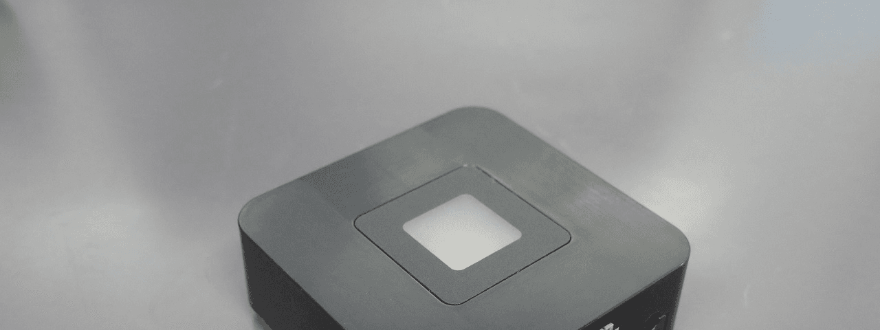
KUT2NV9
Feb 19, 2020Garage Door Controller Mini Nova Hub
Equipment Class
DXT - Part 15 Low Power Transceiver, Rx Verified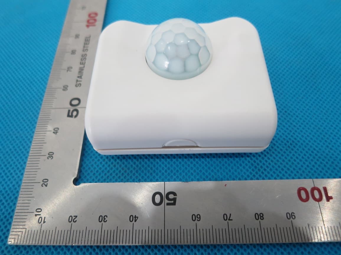
KUTPS10X
Sep 09, 2014Motion Sensor
Equipment Class
DSC - Part 15 Security/Remote Control Transmitter
KUTMKA315
Aug 27, 2014315MHz remote control
Equipment Class
DSC - Part 15 Security/Remote Control Transmitter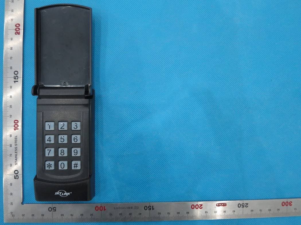
KUTKN103
Jul 16, 2014Wireless keypad
Equipment Class
DSC - Part 15 Security/Remote Control Transmitter