KUTSC001Control Panel (433.92MHz Tx)
Capital Prospect Ltd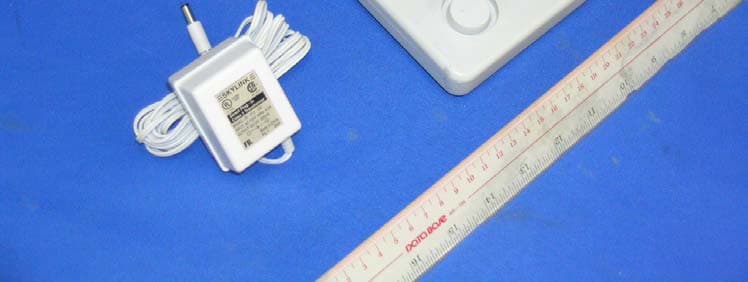
Click to zoom
Application Details
- Equipment Class
- DSR - Part 15 Remote Control/Security Device Transceiver
- Date of Grant
- Jan 04, 2007
- Application Purpose
- Original Equipment
- Date of Application
- Jan 04, 2007
- Equipment Note
- Control Panel (433.92MHz Tx)
- Frequency Range
- 433.92000000 - 433.92000000
- Company
- Capital Prospect Ltd
- Country
- Hong Kong
Documents & Files
Document Text
Text extracted from the exhibit documents filed with the FCC. Open a document above to read the original.
Users Manual
CUSTOMER SERVICE 17 Sheard Avenue, Brampton, Ontario, Canada L6Y 1J3 Tel / Téléphone : (800) 304-1187 Fax / Télécopieur : (800) 286-1320 Email / Courrier électronique : [email protected] P/N. 101A063-005OCT, 2004 MODEL / MODÈLE / MODELO : SC-100 Total Protection Alarm System Système de Sécurité sans fil Sistema de Alarma con Protección Total www.skylinkhome.com /MD/MR English Francais Español PAT. D410633 6243000B1 Total Protection Alarm System MODEL: SC-100 USER'S INSTRUCTIONS English –1– SKYLINK TECHNOLOGIES INC. Your Guide to the Total Protection Alarm System MODEL: SC-100 –2– PACKAGE CONTENTS......................................................................................................3 OVERVIEW...........................................................................................................................4 PLANNING YOUR HOME SECURITY NEEDS..............................................................5 INSTALLATION -Control Panel...................................................................................................................6 -Door/Window Sensor.....................................................................................................7 -Motion Sensor.............................................................................................................. 8-9 TESTING YOUR SYSTEM................................................................................................10 LIGHTS AND SOUNDS....................................................................................................11 STANDARD PROGRAMMING....................................................................................12-15 -Arming and disarming the Security System using the Keypad.......................12-13 -Arming and disarming the Security System using the Keychain Transmitter....14 -Panic Button on the Keychain Transmitter................................................................15 PASSWORDS...............................................................................................................16-17 -Master Personal Identification Number (MPIN).......................................................16 -Secondary Personal Identification Number (SPIN)................................................17 ADVANCED PROGRAMMING....................................................................................18-22 -Program Sensors to Different Zones........................................................................18 -To clear a zone............................................................................................................19 -To program a sensor to a zone...............................................................................19 -To delete a Keychain Transmitter from zone 5.....................................................20 -To program a Keychain Transmitter or keypad transmitter (option) to zone 5....... 20 -Standard Arming Sequences..................................................................................... 21 -Additional Arming Sequences.............................................................................. 21-22 -Customize a Sequence............................................................................................... 22 SUMMARY OF ARMING SEQUENCES.........................................................................23 BATTERY MAINTENANCE......................................................................................... 24-26 -Control Panel.................................................................................................................24 -Motion Sensor................................................................................................................25 -Door/Window Sensor...................................................................................................26 -Keychain Transmitter................................................................................................... 26 ADDITIONAL ACCESSORIES (OPTION)............................................................... 27-29 TABLE OF CONTENTS The SC-100 Total Protection Alarm System contains all the above items. PACKAGE CONTENTS Everything required for installation is included with this package 1 Control Panel (SC-001) includes: 1 antenna (installed) 1 AC adapter 1 9 volt alkaline battery Two sets of Door/Window Sensors (WT-433), each set includes: 1 transmitter 1 magnetic switch 1 magnet 2 spacers 1 12 volt alkaline battery (installed) 1 Motion Sensor (PS-434A) includes: 1 9 volt alkaline battery 1 Keychain Transmitter (4B-434) includes: 1 12 volt alkaline battery (installed) 3 Packs of screws and anchors (for Control Panel, Door/Window Sensors and Motion Sensor) Sheet of templates Double Sided Tape (to aid in the installation of the Control Panel, Door/Window Sensors and Motion Sensor) Warning Stickers 2 pcs User's instructions Warranty Card Quick Guide –4– OVERVIEW Congratulations! You have just purchased one of the most reliable and up-to-date wireless security systems on the market today. Skylink is the first company to incorporate the rolling code technology in a home/business security system. This innovative technology provides increased security and trouble free wireless connections which greatly reduces false alarms. It guarantees that the Control Panel will only recognize radio waves from it’s remote sensors, (door/window sensor, motion sensor and the keychain transmitter), which prevents high tech thieves from duplicating signals and tampering with your system. This user's instructions is divided into 6 categories. 1. Planning, Installation and Testing (pages 5-10) - explains how to plan a security strategy. - how to install the Control Panel and the remote devices, (door/window sensor and the motion sensor). - once everything is installed, explains how to test each device. 2. Lights and Sounds (page 11) - explains the function of all the lights on the Control Panel. - des…
Text truncated - open the document above for the full version.
Users Manual
CUSTOMER SERVICE 17 Sheard Avenue, Brampton, Ontario, Canada L6Y 1J3 Tel / Téléphone : (800) 304-1187 Fax / Télécopieur : (800) 286-1320 Email / Courrier électronique : [email protected] P/N. 101A063-005OCT, 2004 MODEL / MODÈLE / MODELO : SC-100 Total Protection Alarm System Système de Sécurité sans fil Sistema de Alarma con Protección Total www.skylinkhome.com /MD/MR English Francais Español PAT. D410633 6243000B1 Total Protection Alarm System MODEL: SC-100 USER'S INSTRUCTIONS English –1– SKYLINK TECHNOLOGIES INC. Your Guide to the Total Protection Alarm System MODEL: SC-100 –2– PACKAGE CONTENTS......................................................................................................3 OVERVIEW...........................................................................................................................4 PLANNING YOUR HOME SECURITY NEEDS..............................................................5 INSTALLATION -Control Panel...................................................................................................................6 -Door/Window Sensor.....................................................................................................7 -Motion Sensor.............................................................................................................. 8-9 TESTING YOUR SYSTEM................................................................................................10 LIGHTS AND SOUNDS....................................................................................................11 STANDARD PROGRAMMING....................................................................................12-15 -Arming and disarming the Security System using the Keypad.......................12-13 -Arming and disarming the Security System using the Keychain Transmitter....14 -Panic Button on the Keychain Transmitter................................................................15 PASSWORDS...............................................................................................................16-17 -Master Personal Identification Number (MPIN).......................................................16 -Secondary Personal Identification Number (SPIN)................................................17 ADVANCED PROGRAMMING....................................................................................18-22 -Program Sensors to Different Zones........................................................................18 -To clear a zone............................................................................................................19 -To program a sensor to a zone...............................................................................19 -To delete a Keychain Transmitter from zone 5.....................................................20 -To program a Keychain Transmitter or keypad transmitter (option) to zone 5....... 20 -Standard Arming Sequences..................................................................................... 21 -Additional Arming Sequences.............................................................................. 21-22 -Customize a Sequence............................................................................................... 22 SUMMARY OF ARMING SEQUENCES.........................................................................23 BATTERY MAINTENANCE......................................................................................... 24-26 -Control Panel.................................................................................................................24 -Motion Sensor................................................................................................................25 -Door/Window Sensor...................................................................................................26 -Keychain Transmitter................................................................................................... 26 ADDITIONAL ACCESSORIES (OPTION)............................................................... 27-29 TABLE OF CONTENTS The SC-100 Total Protection Alarm System contains all the above items. PACKAGE CONTENTS Everything required for installation is included with this package 1 Control Panel (SC-001) includes: 1 antenna (installed) 1 AC adapter 1 9 volt alkaline battery Two sets of Door/Window Sensors (WT-433), each set includes: 1 transmitter 1 magnetic switch 1 magnet 2 spacers 1 12 volt alkaline battery (installed) 1 Motion Sensor (PS-434A) includes: 1 9 volt alkaline battery 1 Keychain Transmitter (4B-434) includes: 1 12 volt alkaline battery (installed) 3 Packs of screws and anchors (for Control Panel, Door/Window Sensors and Motion Sensor) Sheet of templates Double Sided Tape (to aid in the installation of the Control Panel, Door/Window Sensors and Motion Sensor) Warning Stickers 2 pcs User's instructions Warranty Card Quick Guide –4– OVERVIEW Congratulations! You have just purchased one of the most reliable and up-to-date wireless security systems on the market today. Skylink is the first company to incorporate the rolling code technology in a home/business security system. This innovative technology provides increased security and trouble free wireless connections which greatly reduces false alarms. It guarantees that the Control Panel will only recognize radio waves from it’s remote sensors, (door/window sensor, motion sensor and the keychain transmitter), which prevents high tech thieves from duplicating signals and tampering with your system. This user's instructions is divided into 6 categories. 1. Planning, Installation and Testing (pages 5-10) - explains how to plan a security strategy. - how to install the Control Panel and the remote devices, (door/window sensor and the motion sensor). - once everything is installed, explains how to test each device. 2. Lights and Sounds (page 11) - explains the function of all the lights on the Control Panel. - des…
Text truncated - open the document above for the full version.
Users Manual
CUSTOMER SERVICE 17 Sheard Avenue, Brampton, Ontario, Canada L6Y 1J3 Tel / Téléphone : (800) 304-1187 Fax / Télécopieur : (800) 286-1320 Email / Courrier électronique : [email protected] P/N. 101A063-005OCT, 2004 MODEL / MODÈLE / MODELO : SC-100 Total Protection Alarm System Système de Sécurité sans fil Sistema de Alarma con Protección Total www.skylinkhome.com /MD/MR English Francais Español PAT. D410633 6243000B1 Total Protection Alarm System MODEL: SC-100 USER'S INSTRUCTIONS English –1– SKYLINK TECHNOLOGIES INC. Your Guide to the Total Protection Alarm System MODEL: SC-100 –2– PACKAGE CONTENTS......................................................................................................3 OVERVIEW...........................................................................................................................4 PLANNING YOUR HOME SECURITY NEEDS..............................................................5 INSTALLATION -Control Panel...................................................................................................................6 -Door/Window Sensor.....................................................................................................7 -Motion Sensor.............................................................................................................. 8-9 TESTING YOUR SYSTEM................................................................................................10 LIGHTS AND SOUNDS....................................................................................................11 STANDARD PROGRAMMING....................................................................................12-15 -Arming and disarming the Security System using the Keypad.......................12-13 -Arming and disarming the Security System using the Keychain Transmitter....14 -Panic Button on the Keychain Transmitter................................................................15 PASSWORDS...............................................................................................................16-17 -Master Personal Identification Number (MPIN).......................................................16 -Secondary Personal Identification Number (SPIN)................................................17 ADVANCED PROGRAMMING....................................................................................18-22 -Program Sensors to Different Zones........................................................................18 -To clear a zone............................................................................................................19 -To program a sensor to a zone...............................................................................19 -To delete a Keychain Transmitter from zone 5.....................................................20 -To program a Keychain Transmitter or keypad transmitter (option) to zone 5....... 20 -Standard Arming Sequences..................................................................................... 21 -Additional Arming Sequences.............................................................................. 21-22 -Customize a Sequence............................................................................................... 22 SUMMARY OF ARMING SEQUENCES.........................................................................23 BATTERY MAINTENANCE......................................................................................... 24-26 -Control Panel.................................................................................................................24 -Motion Sensor................................................................................................................25 -Door/Window Sensor...................................................................................................26 -Keychain Transmitter................................................................................................... 26 ADDITIONAL ACCESSORIES (OPTION)............................................................... 27-29 TABLE OF CONTENTS The SC-100 Total Protection Alarm System contains all the above items. PACKAGE CONTENTS Everything required for installation is included with this package 1 Control Panel (SC-001) includes: 1 antenna (installed) 1 AC adapter 1 9 volt alkaline battery Two sets of Door/Window Sensors (WT-433), each set includes: 1 transmitter 1 magnetic switch 1 magnet 2 spacers 1 12 volt alkaline battery (installed) 1 Motion Sensor (PS-434A) includes: 1 9 volt alkaline battery 1 Keychain Transmitter (4B-434) includes: 1 12 volt alkaline battery (installed) 3 Packs of screws and anchors (for Control Panel, Door/Window Sensors and Motion Sensor) Sheet of templates Double Sided Tape (to aid in the installation of the Control Panel, Door/Window Sensors and Motion Sensor) Warning Stickers 2 pcs User's instructions Warranty Card Quick Guide –4– OVERVIEW Congratulations! You have just purchased one of the most reliable and up-to-date wireless security systems on the market today. Skylink is the first company to incorporate the rolling code technology in a home/business security system. This innovative technology provides increased security and trouble free wireless connections which greatly reduces false alarms. It guarantees that the Control Panel will only recognize radio waves from it’s remote sensors, (door/window sensor, motion sensor and the keychain transmitter), which prevents high tech thieves from duplicating signals and tampering with your system. This user's instructions is divided into 6 categories. 1. Planning, Installation and Testing (pages 5-10) - explains how to plan a security strategy. - how to install the Control Panel and the remote devices, (door/window sensor and the motion sensor). - once everything is installed, explains how to test each device. 2. Lights and Sounds (page 11) - explains the function of all the lights on the Control Panel. - des…
Text truncated - open the document above for the full version.
Block Diagram
A INITIAL RELEASE PREAMP 433.92MHz Q5 SUPERREGEN LBPAMP PROPRIETARY INFO SCHMITTTOGGLE LEDBACKLITE LED INDICATOR OSCILLATORUHFQ7 433.92MHz RFMODULATOR Y2SAW 433.92MHz DS19-22 DS3-10 U7A U7B DETECTQ4 JACK U5 12V DCJ1 VOLTAGEREGULATOR U6VOLTAGEREGULATOR 5V KEYPADMATRIX 3V6 MCU U1 EEPROMU4BUZZERDRIVERQ2,3 12 BUZZER TAMPERSWITCHSW1 Y14MHz 12 C1 12 C2 LOW BATTDETECTIONU9 9V DCJACKBT1 CA CAPITAL PROSPECT LTD.SC-001 BLOCK DIAGRAM
Block Diagram
A INITIAL RELEASE PREAMP 433.92MHz Q5 SUPERREGEN LBPAMP PROPRIETARY INFO SCHMITTTOGGLE LEDBACKLITE LED INDICATOR OSCILLATORUHFQ7 433.92MHz RFMODULATOR Y2SAW 433.92MHz DS19-22 DS3-10 U7A U7B DETECTQ4 JACK U5 12V DCJ1 VOLTAGEREGULATOR U6VOLTAGEREGULATOR 5V KEYPADMATRIX 3V6 MCU U1 EEPROMU4BUZZERDRIVERQ2,3 12 BUZZER TAMPERSWITCHSW1 Y14MHz 12 C1 12 C2 LOW BATTDETECTIONU9 9V DCJACKBT1 CA CAPITAL PROSPECT LTD.SC-001 BLOCK DIAGRAM
Block Diagram
A INITIAL RELEASE PREAMP 433.92MHz Q5 SUPERREGEN LBPAMP PROPRIETARY INFO SCHMITTTOGGLE LEDBACKLITE LED INDICATOR OSCILLATORUHFQ7 433.92MHz RFMODULATOR Y2SAW 433.92MHz DS19-22 DS3-10 U7A U7B DETECTQ4 JACK U5 12V DCJ1 VOLTAGEREGULATOR U6VOLTAGEREGULATOR 5V KEYPADMATRIX 3V6 MCU U1 EEPROMU4BUZZERDRIVERQ2,3 12 BUZZER TAMPERSWITCHSW1 Y14MHz 12 C1 12 C2 LOW BATTDETECTIONU9 9V DCJACKBT1 CA CAPITAL PROSPECT LTD.SC-001 BLOCK DIAGRAM
External Photos
External Photo FCC ID : KUTSC001 External Photo - front External Photo - rear
External Photos
External Photo FCC ID : KUTSC001 External Photo - front External Photo - rear
External Photos
External Photo FCC ID : KUTSC001 External Photo - front External Photo - rear
ID Label/Location Info
SKYLINK TECHNOLOGIES CANADA FCC ID : KUTSC001 IC: 4454A-SC001 Model: SC-001 Assembled in China ® CPL CAPITAL PROSPECT LTD. MODEL : SC-001LABELLING DIAGRAMDATE : 2 JUN. 2006PAGE:1OF1 PROPRIETARY INFORMATION FCC LABELSIZE : 32X25MM This device complies with Part 15 of theFCC Rules. Operation is subject to thefollowing two conditions: (1) This devicemay not cause harmful interference, and(2) This device must accept any inter-ference received, including interference that may cause undesired operation.
ID Label/Location Info
SKYLINK TECHNOLOGIES CANADA FCC ID : KUTSC001 IC: 4454A-SC001 Model: SC-001 Assembled in China ® CPL CAPITAL PROSPECT LTD. MODEL : SC-001LABELLING DIAGRAMDATE : 2 JUN. 2006PAGE:1OF1 PROPRIETARY INFORMATION FCC LABELSIZE : 32X25MM This device complies with Part 15 of theFCC Rules. Operation is subject to thefollowing two conditions: (1) This devicemay not cause harmful interference, and(2) This device must accept any inter-ference received, including interference that may cause undesired operation.
ID Label/Location Info
SKYLINK TECHNOLOGIES CANADA FCC ID : KUTSC001 IC: 4454A-SC001 Model: SC-001 Assembled in China ® CPL CAPITAL PROSPECT LTD. MODEL : SC-001LABELLING DIAGRAMDATE : 2 JUN. 2006PAGE:1OF1 PROPRIETARY INFORMATION FCC LABELSIZE : 32X25MM This device complies with Part 15 of theFCC Rules. Operation is subject to thefollowing two conditions: (1) This devicemay not cause harmful interference, and(2) This device must accept any inter-ference received, including interference that may cause undesired operation.
Internal Photos
Internal Photo FCC ID : KUTSC001 Internal Photo - 1 Internal Photo - 2 Internal Photo FCC ID : KUTSC001 Internal Photo - 3
Internal Photos
Internal Photo FCC ID : KUTSC001 Internal Photo - 1 Internal Photo - 2 Internal Photo FCC ID : KUTSC001 Internal Photo - 3
Internal Photos
Internal Photo FCC ID : KUTSC001 Internal Photo - 1 Internal Photo - 2 Internal Photo FCC ID : KUTSC001 Internal Photo - 3
Operational Description
Rm. 03, 13/F., Block. B, Veristrong Ind. Centre, 34-36 Au Pui Wan Street, Fo Tan, N.T., Hong Kong. Tel: (852) 2602 1318 Fax: (852) 2602 4684 Email : [email protected] Model SC-001 APPLICATION for FCC KUTSC001 Confidential Information Jun 24, 2006 3 TECHNICAL DESCRIPTION MODEL SC-001 SECURITY CONSOLE DESCRIPTION The console unit consists of three functional portion, namely digital control portion, radio frequency transmitter and receiver. The digital portion is controlled by a micro-controller which continuously monitors the system status, interfaces with the operation through the keypad, LEDs, and buzzer. It also encodes the data before transmission and decodes the data after reception. Following is a description of each functional block. FUNCTION Voltage Regulator The input of the voltage regulator can accept 12VDC adapter output or 9V battery. Normally it consumes power from the DC adapter. In case of a mains power failure, the 9V battery can maintain normal operation until recovery of mains power. In the presence of DC adapter, only a few micro-ampere of current is drawn from the battery for battery level detection. Low Battery Detection The low battery detection circuit uses a comparator with hysterisis to compare the battery voltage and the 5V reference voltage from the fixed voltage regulator. The battery voltage is scaled down by a voltage divider before feeding to the comparator input. The threshold voltage is determined by the ratio of the resistor values. The values used in the circuit has a threshold voltage of 7.8V. Micro-controller The micro-controller is an 8-bit microprocessor with built-in ROM, RAM, I/O and timer/counter. The external clock frequency is 4 MHz. Non-volatile Storage Non-volatile storage is achieved by EEPROM memory device. It is necessary in the system because the rolling code format of RF data communication require a sequence code which is calculated from previous communication. Therefore it must be maintained during total power removal. Other parameters such as passwords, factory programmed options, device ID codes, etc. can also take advantage of the non-volatile storage. Key Matrix A four-by-four key matrix provides user input capability. The console have features such as alarm reset, password setting, zone configuration, etc. In addition, it has a panic key which will transmit a signal for other peripheral devices upon depression. A tamper switch is connected in parallel Rm. 03, 13/F., Block. B, Veristrong Ind. Centre, 34-36 Au Pui Wan Street, Fo Tan, N.T., Hong Kong. Tel: (852) 2602 1318 Fax: (852) 2602 4684 Email : [email protected] Model SC-001 APPLICATION for FCC KUTSC001 Confidential Information Jun 24, 2006 4 with the panic key so that the former will be triggered when the console is being destructed by violence. LED Display System operating status is indicated by LEDs. The AC power LED indicates presence of DC adapter. The low battery LED will blink when the battery drops low. The arm LED indicates whether the system is in arm or disarm status. The zone LEDs indicate the status of the corresponding zone. A tamper switch is connected in series with the low battery LED. This switch detects cover opening. Sound Generation Different zones including the siren are generated by the micro-controller. A peaking coil is used to amplify the output of the micro-controller to a peak value of nearly a hundred volt which drives a PIEZO-electric buzzer. For normal sound level, a resistor is connected in series to reduce the volume. For siren sound, the resistor is bypassed so as to provide maximum sound pressure. RF Transmitter The RF transmitter uses saturated amplitude modulation for the data signal. The carrier frequency is generated by means of a SAW resonator. The data frame uses a rolling code format which means that the data content is different for each transmission. The data frame will be sent out ten times for each transmission, hence a total transmission time of two second. RF Receiver The RF receiver uses a super-regenerative circuitry. The demodulated signal is then magnified to saturation by a two-stage amplifier. The digital signal is then feed to the micro-controller for decoding. Warning: Changes or modifications to this unit not expressly approved by the party responsible of compliance could void the user’s authority to operate the equipment.
Operational Description
Rm. 03, 13/F., Block. B, Veristrong Ind. Centre, 34-36 Au Pui Wan Street, Fo Tan, N.T., Hong Kong. Tel: (852) 2602 1318 Fax: (852) 2602 4684 Email : [email protected] Model SC-001 APPLICATION for FCC KUTSC001 Confidential Information Jun 24, 2006 3 TECHNICAL DESCRIPTION MODEL SC-001 SECURITY CONSOLE DESCRIPTION The console unit consists of three functional portion, namely digital control portion, radio frequency transmitter and receiver. The digital portion is controlled by a micro-controller which continuously monitors the system status, interfaces with the operation through the keypad, LEDs, and buzzer. It also encodes the data before transmission and decodes the data after reception. Following is a description of each functional block. FUNCTION Voltage Regulator The input of the voltage regulator can accept 12VDC adapter output or 9V battery. Normally it consumes power from the DC adapter. In case of a mains power failure, the 9V battery can maintain normal operation until recovery of mains power. In the presence of DC adapter, only a few micro-ampere of current is drawn from the battery for battery level detection. Low Battery Detection The low battery detection circuit uses a comparator with hysterisis to compare the battery voltage and the 5V reference voltage from the fixed voltage regulator. The battery voltage is scaled down by a voltage divider before feeding to the comparator input. The threshold voltage is determined by the ratio of the resistor values. The values used in the circuit has a threshold voltage of 7.8V. Micro-controller The micro-controller is an 8-bit microprocessor with built-in ROM, RAM, I/O and timer/counter. The external clock frequency is 4 MHz. Non-volatile Storage Non-volatile storage is achieved by EEPROM memory device. It is necessary in the system because the rolling code format of RF data communication require a sequence code which is calculated from previous communication. Therefore it must be maintained during total power removal. Other parameters such as passwords, factory programmed options, device ID codes, etc. can also take advantage of the non-volatile storage. Key Matrix A four-by-four key matrix provides user input capability. The console have features such as alarm reset, password setting, zone configuration, etc. In addition, it has a panic key which will transmit a signal for other peripheral devices upon depression. A tamper switch is connected in parallel Rm. 03, 13/F., Block. B, Veristrong Ind. Centre, 34-36 Au Pui Wan Street, Fo Tan, N.T., Hong Kong. Tel: (852) 2602 1318 Fax: (852) 2602 4684 Email : [email protected] Model SC-001 APPLICATION for FCC KUTSC001 Confidential Information Jun 24, 2006 4 with the panic key so that the former will be triggered when the console is being destructed by violence. LED Display System operating status is indicated by LEDs. The AC power LED indicates presence of DC adapter. The low battery LED will blink when the battery drops low. The arm LED indicates whether the system is in arm or disarm status. The zone LEDs indicate the status of the corresponding zone. A tamper switch is connected in series with the low battery LED. This switch detects cover opening. Sound Generation Different zones including the siren are generated by the micro-controller. A peaking coil is used to amplify the output of the micro-controller to a peak value of nearly a hundred volt which drives a PIEZO-electric buzzer. For normal sound level, a resistor is connected in series to reduce the volume. For siren sound, the resistor is bypassed so as to provide maximum sound pressure. RF Transmitter The RF transmitter uses saturated amplitude modulation for the data signal. The carrier frequency is generated by means of a SAW resonator. The data frame uses a rolling code format which means that the data content is different for each transmission. The data frame will be sent out ten times for each transmission, hence a total transmission time of two second. RF Receiver The RF receiver uses a super-regenerative circuitry. The demodulated signal is then magnified to saturation by a two-stage amplifier. The digital signal is then feed to the micro-controller for decoding. Warning: Changes or modifications t…
Text truncated - open the document above for the full version.
Contact Information
Applicant
Joe Ng(Project Manager)
Technical Contact
Intertek Testing Services Hong Kong Ltd.Billy Chow
[email protected](852)2173-8528
2/F., Garment Centre, · Kowloon · Hong Kong
Non-Technical Contact
Intertek Testing Services Hong Kong Ltd.Billy Chow
[email protected](852)2173-8528
Test Firm
Intertek Testing Services Hong KongBilly Chow
Technical Specifications
| # | Rule Parts | Frequency Range | Power Output |
|---|---|---|---|
| 1 | 15.231 | 433.92 MHz - 433.92 MHz | - |
Other Applications from Capital Prospect Ltd

KUTSM001
Jun 25, 2023Side Mount Garage Door Opener
Equipment Class
DXX - Part 15 Low Power Communication Device Transmitter
KUT2NV9
Feb 19, 2020Garage Door Controller Mini Nova Hub
Equipment Class
DXT - Part 15 Low Power Transceiver, Rx Verified
KUTPS10X
Sep 09, 2014Motion Sensor
Equipment Class
DSC - Part 15 Security/Remote Control Transmitter
KUTMKA315
Aug 27, 2014315MHz remote control
Equipment Class
DSC - Part 15 Security/Remote Control Transmitter
KUTKN103
Jul 16, 2014Wireless keypad
Equipment Class
DSC - Part 15 Security/Remote Control Transmitter