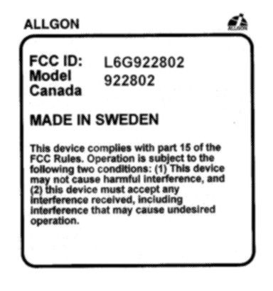
L6G922802
Powerwave Technologies Inc.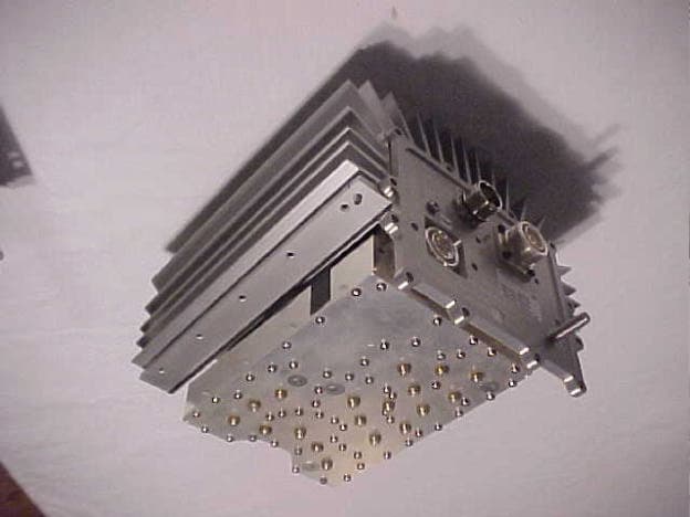
Click to zoom
Application Details
- Equipment Class
- PCB - PCS Licensed Transmitter
- Date of Grant
- Nov 14, 1999
- Application Purpose
- Original Equipment
- Date of Application
- Sep 09, 1999
- Frequency Range
- 1950.00000000 - 1970.00000000
- Company
- Powerwave Technologies Inc.
- Country
- United States
Documents & Files
Document Text
Text extracted from the exhibit documents filed with the FCC. Open a document above to read the original.
Users Manual
TTPA Installation Guide (draft version) Disclaimer The information contained in this publication has been carefully reviewed to ensure it’s accuracy. However, since the possibility for errors can never be entirely eliminated, Allgon System AB assumes no responsibility for any inaccuracies or errors in the information contained herein. This information does not convey to the purchaser or user of any product described in this publication any license under any patent, copyright, trade secret or other intellectual property, unless otherwise stated by written agreement by Allgon System AB. Allgon System AB, and it’s affiliates, reserve the right to change any specification, design, model and any other information contained herein without notice. Allgon System AB does not assume any liability arising out of, or associated with, the application or use of any product or item described herein. The products from Allgon System AB are not designed, intended or authorized, for use as components in systems or applications intended to support or sustain life, or for any nuclear facility application, or for any other application in which the failure of the product(s) could create a situation where personal injury or death may occur. Allgon System AB will not knowingly sell it’s products for use in such applications, and the buyer shall indemnify and hold harmless Allgon System AB and it’s employees, subsidiaries, affiliates, representatives and distributors against all claims, costs, damages, expenses, court and attorney fees arising out of, directly or indirectly, any claim of personal injury or death associated with such unintended or unauthorized use, even if such claim alleges that Allgon System AB was negligent regarding the design or manufacture of the product. Contents 1.General Information4 Overview4 Safety Considerations4 2.Installation of the TTPA2 Outdoor conditions2 Dimensions2 Mounting equipment2 Checklist before mounting and installation2 Installation procedure for TTPA2 Checklist after mounting and installation4 3. Installation of CI5 General5 Outdoor and indoor conditions5 Mounting equipment5 Checklist before mounting and installation5 Installation procedure for CI5 Checklist after mounting and installation6 4. Installation of APDU6 General6 Outdoor and indoor conditions6 Dimensions7 Mounting equipment7 Checklist before mounting and installation7 Installation procedure for APDU in BTS8 Checklist after mounting and installation8 5. Commissioning8 Appendix 1. TTPA Software Settings9 Optimising coverage9 General link budget characterisation, step by step9 Appendix 2: System Configuration Examples11 Configuration I11 Configuration II12 Configuration III13 Configuration IV14 Acronyms and Abbreviations APDUAlarm and Power Distribution Unit BTSBase Tranceiver System CICurrent Injector DMMDigital Multi Meter ESDElectro Static Discharge LEDLight Emitting Diod LNALow Noise Amplifier MTBFMean Time Between Failures MTTRMean Time To Replace NFNoise figure TTATower Top Amplifier TTPA Tower Top Power Amplifier 1.General Information Overview The physical installation of each part of the TTPA system is described in separate chapters. Testing and functioning check is described in a separate chapter. Different kinds of system configurations are described in the last chapter. Note that at some stages during the installation, the BTS must be turned off. To prevent extensive downtime it may be useful to finish the stages of the installation of both TTPA, APDU and CI when the BTS still is active. The BTS then has to be shut down only once for finishing the installation of all included parts. Note that all information in this manual may change without any notice. Refer to the technical specifications for the latest information on the TTPA products. Safety Considerations The TTPA is equipped with a pole clamping unit. This enables the installation personnel to first install the relatively light mast clamp, and then easily hook on the actual amplifier. This feature reduces the risk of accidents during installation. It is important for everyone involved in the installation, operation, and maintenance of the TTPA, APDU and CI to understand the following points: •The TTPA, APDU, and CI are designed to amplify the uplink signal from the mobile phone and the downlink signal to the mobile phone. The TTPA system must be used exclusively for this purpose and no other. •No units included in the system (TTPA, APDU or CI) may be repaired in the field. All malfunctioning parts must be sent back to Allgon Systems for repair or replacement. •Always use an ESD bracelet during installation of electrical equipment and when touching the BTS connectors, or when handling electrical equipment, to prevent ESD damage. •The mounting of the TTPA on high masts, poles or roofs must be done by skilled personnel, authorised to work on high masts, poles, or roofs. The personnel must be aware of security regulations and use appropriate security equipment. •The coaxial cable insulation is made of PTFE, polytetrafluoroethylene, which gives off small amounts of hydrogen fluoride when heated. Hydrogen fluoride is poisonous. Heating tools must not be used when stripping off coaxial cable insulation. No particular measures are to be taken in case of fire, because the emitted concentration of hydrogen fluoride is very low. 2.Installation of the TTPA Outdoor conditions The TTPA is environmentally protected (IP 65), and can be mounted without any kind of protection from bad weather conditions. However, it is not permitted to install the TTPA in bad weather conditions. If the bad weather conditions are of a short duration, and the TTPA and all other connectors that are to be connected during the installation are protected, the installation may continue not less than one hour after the adverse conditions have ended. Dimensions Weight is 12 kilos for TTPA unit, 3 kilo for clamping unit. Mounting equipment A standard mounting kit is delivered with each TTP…
Text truncated - open the document above for the full version.
Operational Description
ALLGON TELECOM, Ltd. 7317 Jack Newell Blvd. North, Fort Worth, Texas 76118 www.allgon.com Telephone: (817) 595-9999 Fax: (817) 595-7999 Toll Free: 1-888-ALLGON1 Chris Harvey, EMC Lab Director MET Laboratories, Inc. 914 West Patapsco Ave. Baltimore, MD 21230 RE: L6G922802 Dear Mr. Harvey, The Allgon tower-top amplifier (L6G922802) is designed and intended for use in single carrier mode only. Due to the configuration of the technology in which the TTPA will be used, only one carrier will be possible per TTPA. The unit will be used with a single GMSK modulated carrier. Best Regards, Tim Purvis 9-10-99
Test Report
FCC ID: L6G922802 September 13, 1999 Federal Communications Commission Authorization and Evaluation Division 7435 Oakland Mills Road Columbia, MD 21046 Attention:Applications Examiner Applicant:Allgon Enterprises, Inc. 7317 Jack Newell Blvd. North Fort Worth, Texas 76118 Equipment:AMPS Cellular Repeater, Model: 9228.02 FCC ID: L6G922802 Specification:47 CFR Part 24 Licensed Certification Dear Examiner: The following application for Grant of Equipment Authorization is presented on behalf of Allgon Enterprises, Inc. for the Licensed Certification of their Model: 9228.02, PCS Cellular Repeater. Enclosed, please find a complete data and documentation package demonstrating that this device complies with the technical requirements of 47 CFR, Part 24, for a Cellular Repeater. If you have any questions, please contact the undersigned, who is authorized to act as Agent. Sincerely, Chris Harvey Director, EMC Laboratory FCC ID: L6G922802 EMI1186A- 2 -April 19, 1999 MET Laboratories, Inc. Safety Certification - EMI - Telecom Environmental Simulation 914 WEST PATAPSCO AVENUE !! BALTIMORE, MARYLAND 21230-3432 !! PHONE (410) 354-3300 !! FAX (410) 354-3313 ENGINEERING TEST REPORT in support of the Application for Grant of Equipment Authorization EQUIPMENT:PCS Cellular Repeater, Model 9228.02 FCC ID::L6G922802 Specification:47 CFR 24 On Behalf of the Applicant:Allgon Enterprises, Inc. 7317 Jack Newell Blvd. North FortWorth, TX 76118 Manufacturer:Allgon Enterprises, Inc. 7317 Jack Newell Blvd. North FortWorth, TX 76118 Manufacturer’s Mr. Tim Purvis Representative Test Date(s):Aug. 16 thru Sept. 9, 1999 ENGINEERING STATEMENT I ATTEST: the measurements shown in this report were made in accordance with the procedures indicated, and that the emissions from this equipment were found to be within the limits applicable. I assume full responsibility for the accuracy and completeness of these measurements. On the basis of the measurements made, the equipment tested is capable of operation in accordance with the requirements of Part 24 of the FCC Rules under normal use and maintenance. _____________________________ Kenneth Bass Sr. EMI Engineer, MET Laboratories FCC ID: L6G922802 EMI1186A- 3 -April 19, 1999 1.0INTRODUCTION The following data is presented on behalf of the Applicant, Allgon Enterprises, Inc., as verification of the compliance of the Allgon PCS Cellular Repeater, Model 9228.02 to the requirements of 47CFR 24. 2.0TEST SITE All testing was conducted at MET Laboratories, Inc., 914 West Patapsco Avenue, Baltimore, Maryland 21230-3493. Radiated emissions measurements were performed on a three-meter open area test site (OATS). A complete site description is on file with the FCC Laboratory Division as 31040/SIT/MET. 3.0TEST EQUIPMENT USED ManufacturerEquipment Calibration DueCal. Interval Hewlett Packard8563A Spectrum Analyzer5/25/00annual EMCOBiconical Antenna 31043/9/00annual EMCOEMCO Log Periodic Antenna2/16/00annual EMCODouble Ridge Guided Horn2/8/00annual Hewlett Packard8594EM Analyzer11/18/99annual Rhode & Swartz (X3)SMIQ 03 Digital Signal Gen.N/A (Verified using HP8563A) N/A SolarLISN7/26/00annual 4.0EQUIPMENT UNDER TEST CONFIGURATION The Cellular Repeater was configured with AC power supply modules and a digital signal generator was used to simulate various PCS (i.e. GMSK Modulation type) cellular RF input signals to the EUT. The EUT with host external computer was configured for maximum signal gain and bandwidth. The EUT was operated in a manner representative of the typical usage of the equipment. During all testing, (with the exception of intermodulation tests), the EUT was configured for Stacked Channel operation which results in maximum possible output gain. 5.0TEST TYPE(S) 5.1Radiated Emissions: 47CFR2.993, 24.238(a) 5.2Occupied Bandwidth: 47CFR2.989, Input vs. Output 5.3RF Power Output: 47CFR 2.985, 24.132(b),(c) 5.4Spurious Emission at Antenna Terminals: (downlink) 47CFR 2.991, 24.238(a) 5.5Intermodulation Spurious Emissions-2 Tone Simultaneous RF Injection (downlink): 47CFR2.991, 24.238(a) 5.6Spurious Emission at Antenna Terminals +/- 1MHz: 47CFR 2.991, 24.238(b) 5.7AC Line Conducted Emissions: 47CFR 15.107 E(V/m) 1m ' 49.2X20 1 E(V/m) 1m '31.37V/mor149.939dbμV 43%10Log(20)'56.01dB 149.939dBμV&56.01dB'93.92dBμV@1m E(V/m) 3m ' 49.2X20 3 E(V/m) 3m '10.4563V/mor140.39dbμV 140.39&56.01'84.38dBμV@3m FCC ID: L6G922802 EMI1186A- 4 -April 19, 1999 6.0TEST RESULTS 6.1TEST TYPE: Radiated Emissions 6.1.1TECHNICAL SPECIFICATION:2.993; 24.238(a) 6.1.2TEST DATE(S):9 September 1999 6.1.3MEASUREMENT PROCEDURES: As required by §2.993, field strength of spurious radiation measurements were made in accordance with the general procedures of ANSI C63.4-1992 "Methods of Measurement of Radio- Noise Emissions from Low-Voltage Electrical and Electronic Equipment in the Range of 9kHz to 40 GHz". Preliminary radiated emission measurements were performed inside a shielded chamber with all digital signal generators on and terminated. The frequency list from the preliminary measurements was used as a guide for making final measurements on a 10 meter open area test site. The unit was scanned over the frequency range of 9 kHz to 20 GHz. The Radiated Spurious Emissions Limit is obtained by the following: Based on an output power (as measured at the output of the Amplifier) of 20 watts: P = 20 W o As per 2.993 (a), it is assumed this power is to be fed to a half-wave tuned dipole. Using a conversion formula for distance, the field strength at one meter can be derived: As per 24.238(a), the spurious emissions must be attenuated by 43 + log(P) which is: Therefore, the limit for spurious emissions is: At 3 meters measurement distance, the limit is; According to 24.238(a), all signals must be attenuated by 56.01 dB. Therefore, the limit for spurious emissions for a test distance of 3 meters is: FCC ID: L6G922802 EMI1186A- 5 -April 19, 1999 6.1.4RESULTS: Carrier Emission:20 Watts FREQUENCYEUTANTENNAEUTANTENNATESTCABLE FIELDLIMITS…
Text truncated - open the document above for the full version.
Test Report
FCC ID: L6G922802 EMI1249A- 12 -April 19, 1999 6.4TEST TYPE: Spurious Emissions at Antenna Terminals 6.4.1TECHNICAL SPECIFICATION:2.991; 24.238(a) 6.4.2TEST DATE(S):20 Aug 1999 6.4.3MEASUREMENT PROCEDURES: As required by §2.991 of CFR 47, spurious emissions at antenna terminal measurements were made at the RF output terminals using a 50 S attenuator and spectrum analyzer set for a 30 kHz bandwidth. This test was performed with Digitally modulated carrier signals. The Digital signal generator was adjusted for continuous transmit on frequencies in both the uplink and down-link frequency bands. The frequency spectrum was investigated from 9.0 KHz to 20.0 GHz. For measuring emissions above 2 GHz, a high-pass filter was used to eliminate the fundamental transmit frequency to prevent possible saturation effects on the front end of the spectrum analyzer. 6.5.4RESULTS: Equipment complies with Section 2.991and 24.238(a) SUMMARY OF SPURIOUS EMISSIONS AT ANTENNA TERMINALS - DownLink (Base) Frequency Range EmissionEmissionLimit FrequencyLevel(dBm) (dBm) 0 - 1 GHz881.7 MHz-22.83-13.1 1 - 2 GHz1.401 GHz-14.00-13.1 2 - 2.90 GHz2.063 GHz-22.83-13.1 2.90 - 5 GHz3.919 GHz-41.00-13.1 5 - 9 GHz5.893 GHz-30.17-13.1 9 - 20.0 GHz19.74 GHz-27.17-13.1 Plots on the following pages illustrate compliance to the required rule parts. FCC ID: L6G922802 EMI1249A- 13 -April 19, 1999 FCC ID: L6G922802 EMI1249A- 14 -April 19, 1999 FCC ID: L6G922802 EMI1249A- 15 -April 19, 1999 FCC ID: L6G922802 EMI1249A- 16 -April 19, 1999 FCC ID: L6G922802 EMI1249A- 17 -April 19, 1999 - FCC ID: L6G922802 EMI1249A- 18 -April 19, 1999 6.6TEST TYPE: Spurious Emissions at Antenna Terminals @ Frequency Block Edge +/- 1MHz 6.6.1TECHNICAL SPECIFICATION:47CFR2.991;24.238(b) 6.6.2TEST DATE(S):16 Aug 1999
Contact Information
Applicant
Robert Biedka(Sr. Quality Engineer)
Technical Contact
MET Laboratories, Inc.Chris R Harvey
[email protected]410-354-3300
914 West Patapsco Ave. · Baltimore, Maryland · United States
Non-Technical Contact
MET Laboratories, Inc.Terri Wolf
[email protected]410-354-3300
Test Firm
MET Laboratories, Inc.John Mason
Technical Specifications
| # | Rule Parts | Frequency Range | Power Output | Emission | Tolerance |
|---|---|---|---|---|---|
| 1 | 24E | 1.95 GHz - 1.97 GHz | 20 W | GXW | 100.0000000000 % |
Other Applications from Powerwave Technologies Inc.
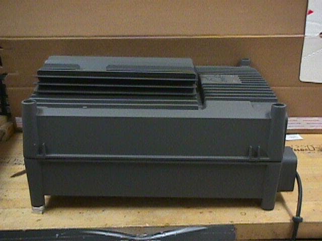
L6GAR4540
Apr 10, 2001Channel Select9ive High-Power Repeater
Equipment Class
AMP - Amplifier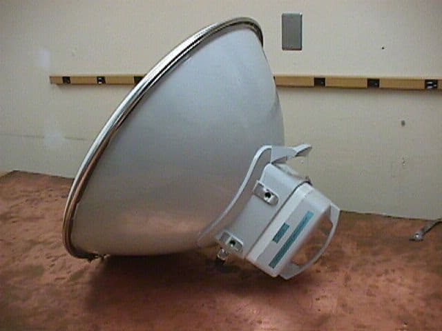
L6GAMR23-1200
Feb 01, 2001Microwave Point-to-Point Radio
Equipment Class
TNB - Licensed Non-Broadcast Station Transmitter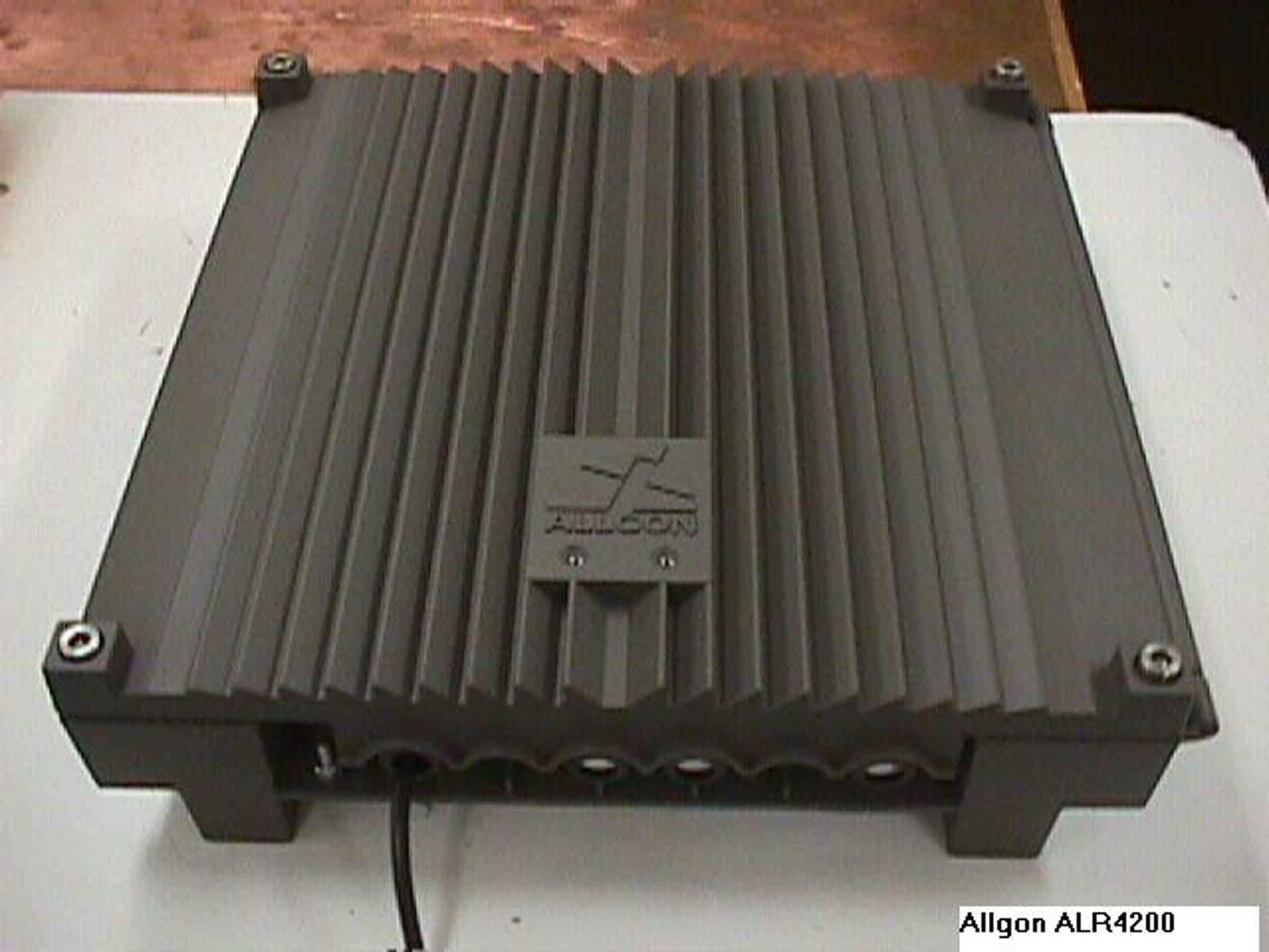
L6GALR4200
Oct 29, 2000Frequency Selective Repeater
Equipment Class
AMP - Amplifier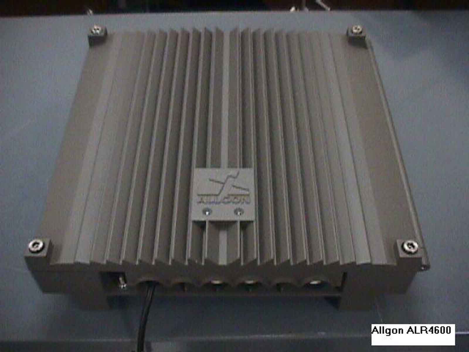
L6GALR4600
Oct 29, 2000Frequency Selective Repeater
Equipment Class
AMP - Amplifier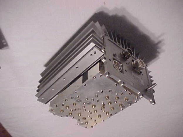
L6G922801
May 08, 2000Tower Top Power Apmilfier/Booster
Equipment Class
AMP - Amplifier