L6GAR3100A2 Channel Extender
Powerwave Technologies Inc.
Click to zoom
Application Details
- Equipment Class
- PCB - PCS Licensed Transmitter
- Date of Grant
- Sep 01, 1999
- Application Purpose
- Original Equipment
- Date of Application
- Jun 13, 1999
- Equipment Note
- 2 Channel Extender
- Frequency Range
- 1930.00000000 - 1990.00000000
- Company
- Powerwave Technologies Inc.
- Country
- United States
Documents & Files
Document Text
Text extracted from the exhibit documents filed with the FCC. Open a document above to read the original.
Users Manual
ALLGON SYSTEM AB REV A Specifications are subject to change without prior notice! MailOffice addressTelephoneTelefax Box 541Propellervägen 6 AOperator: +46-8 540 822 00+46-8 540 824 85 S-183 25 TÄBYTäby SWEDEN PRODUCT SPECIFICATION The Allgon Channel Selective Repeater for GSM-1900 - AR 3100A 1. ELECTRICAL SPECIFICATION Frequency range 1 1850 - 1910 MHz uplink 1930 - 1990 MHz downlink Number of carriers1; 2 optional. Gain 2 50 - 90 dB, adjustable in 1 dB steps Output power38.8 dBm (7.5W) 1 carrier* 35.7 dBm (3.7W) per carrier at 2 carriers* *(-40 dBm drive) Selectivity± 100 kHz> -3 dB ± 400 kHz< -35 dB ± 600 kHz< -45 dB ± 1 MHz< -50 dB ± 5 MHz< -60 dB Noise figure, typical5 dB Max input level-20 dBm (non-destructive) Intermodulation, spuriouses< -36 dBm at 9 kHz - 2 GHz and harmonics< - 30 dBm at 2 GHz - 12,75 GHz Group delay< 5 μs RF-conncectorsN-female Voltage supply115 VAC or 24/48 VDC Power consumption30 - 150 W (depending on no. of used channels and traffic levels) ALLGON SYSTEM AB REV A Specifications are subject to change without prior notice! MailOffice addressTelephoneTelefax Box 541Propellervägen 6 AOperator: +46-8 540 822 00+46-8 540 824 85 S-183 25 TÄBYTäby SWEDEN 2. ALARM AND MONITOR FUNCTIONS Alarms 3 Power supply failureUnlocked PLL DC voltagesPoor antenna isolation External alarmsCU-board failure Monitor functions 3 High temperatureGain Output powerDC testpoints Externally visible indicatorsOperation - yellow LED Alarm - red LED + 2 relay contacts for connection of external alarm eq. Local controlVia PC with OMT program Remote controlVia modem and fixed line to PC or via built-in MS (optional) 3. MECHANICAL SPECIFICATION Dimensions (WxHxD) Dimensions (WxHxD), optional 440 x 530 x 174 mm 440 x 530 x 240mm 17.3 x 20.9 x 6.9 inches 17.3 x 20.9 x 9.4 inches Weight Weight, optional 21 kg 25 kg 46 lbs. 55 lbs. Lock typeABLOY MTBF per 2 channels50000 hours 4. ENVIRONMENTAL SPECIFICATION Temperature range, operation - 25°C to + 55°C- 13°F to + 131°F Casing classIP 55(Water- and dustproof, high pressure) 5. SPECIAL FEATURES • Stability Supervision• Software Download • Radio Signal Strength Indicator• Temperature Supervision • No of active timeslots• Compability with The Allgon Advanced Repeater - OMC 1 The full PCS band is divided into subbands since duplex filter covers 40 Mhz (easily exchangeable in the field). 2 Applicable performance parameters are measured at 85 dB gain 3 Examples of alarms and monitor functions
Users Manual
ALLGON System AB AR Repeaters & OMTIntroduction Introduction Allgon repeaters are used to fill out uncovered areas in cellular mobile systems, such as base station fringe areas, road tunnels, busirEss and industrial buildings, etc. A repeater receives signals from a base station, amplifies and retransmits the signals to mobile stations. Also it receives, amplifies and retransmits signals in the opposite direction. Both directions are served simultaneously. To be able to receive and transmit signals in both directions, the repeater is connected to a donor antenna directed towards the base station and to a service antenna directed towards the area to be covered. Operation of the repeaters is performed using a desktop or notebook and the Allgon OMT (Operation & Maintenance Terminal) which communicate, locally or remotely via modem, with the repeaters. There is also an Allgon OMC (Operation & Maintenance Center), which is intended to be used to run many Allgon AR repeaters. The repeaters and the OMIT is described in this manual. The OMC is described in the Advanced Repeater 0MG, User’s Manual. User’s Manua~ VD2O1 17/EN Rev. 4B 19c8-03 2-1 Figure 2-1. Allgon AR Repeater InstallationAR Repeaters & OMT ALLGON System AB Installing 24 Volt or 48 Volt DC Power Supply Unit You can replace an AC PSU with a 24 Volt or 48 Volt DC PSU as follows: 1.Switch the repeater off and remove the mains plug from the PSU, if not already done (1 in Figure 3-9). 2.Disconnect the two connectors on the PSU. 3. Loosen the three fixing screws using a 5mm Allen key. 4. Remove the PSU from the repeater. 5. Mount the 24/48 Volt DC PSU with the three fixing screws (3). 6.Connect the PSU to the DIA board (2). 7.Connect the DC power cable. The supplied cable has a radiation limiter which is a requirement for the 24/48 Volt unit to be type approved. The cable shall be connected as follows: The + pole shall be connected to one of the left terminals in the PSU connector with the BROWN part of the DC cable. The — pole shall be connected to one of the right terminals in the PSU connector with the BLUE part of the DC cable. 8.When the connection is completed, switch the repeater on. 9. Make sure the yellow LED is lit on the PSU. The DC Power Supply Unit must be galvanically separated from the mains supply with an equipment fulfilling the 1EC65 safety requirements. 3 - 14 Rev. 48 W98-03 User’s Manual VD2O1 171EN Figure 3-9. Replacing the PSU ALLGON System AB AR Repeaters & OMTPC Controlling Band Selective Type e5ndteIe~tiVf~ repeftter ~‘ Figure 5-20. Band selective configuration The left-hand part of the configuration window contains downlink information (BSA board #1 and PA board #1 located to the left in the cabinet or cover). The right-hand part of the configuration window contains uplink information (BSA board #2 and PA board #2 located to the right in the cabinet or cover). The downmost line indicates current band width and the band width status (fixed or adjustable). Fixed band width operation For repeaters equipped with fixed band width BSA boards, the following three fields are changeable: Downlink:Gain Uplink:Set low band edge Gain The values in the remaining fields are automatically calculated from the band width and the uplink/downlink frequency difference. Adjustable band width operation For repeaters equipped with adjustable band width BSA boards, the uplink ‘Set high band edge’ field is also available and changeable. Users Manual VD2O1 1 7/EN Rev. 4B 1998-03 5 - 39 PC ControllingAR Repeaters & OMT ALLGON System AB Field descriptions: Bandselective repeater The band selective repeater, or the band selective part of a combined repeater, can be turned on/off by clicking this box. The PA boards and the AGC (Automatic Gain Control) are turned off when the band selective repeater is switched off. ‘Downlink’ section Low band edge Displays the downlink low band edge related to the uplink low band edge. The difference is depending on the system duplex spacing. High band edge The downlink high band edge related to the band width. Gain The maximum downlink gain, i.e. the total gain from antenna port to antenna port. Setting range: 45dB to 90dB ‘UpIink’ section Set low band edge The lower band edge for the uplink signal. The band edge frequency can be increased or decreased by clicking the arrow buttons. The frequency is changed in 12.5KHz steps. Values can be typed into the field as well. Setting range for this field is depending on the system and BSA boards. Set high band edge For fixed BSA boards, this field displays the uplink high band edge related to the band width. This band edge cannot be changed solely. For adjustable BSA boards, this field is changeable and affects thus the uplink high band edge and thereby the band width. Gain The maximum uplink gain, i.e. the total gain from antenna port to antenna port. Setting range: 45dB to 90dB 5 - 40 Rev. 4B 1998-03 ALLGON System AB PC ControllingAR Repeaters & OMT Main Window Button Bar Main window button functions: Login - see the File menu (page 5-103). Logout - see the File menu (page 5-103). Exit - see the File menu (page 5-103). Configuration - see the Parameters menu (page 5-106). Read status - see the Status menu (page 5-108). Board Testpoints - see the Tests menu (page 5-109). Change active repeater part - see the Hardware menu (page 5-111). Received Repeater Alarms - see the Alarm menu (page 5-112). Repeater Event Log - see the Alarm menu (page 5-112). Alarm Reset! - see the Alarm menu (page 5-112). ___ About - see the Help menu (page 5-113). 5 - 102 Rev. 4B 1998-03 Users Manual VD2O1 17/EN
Attestation Statements
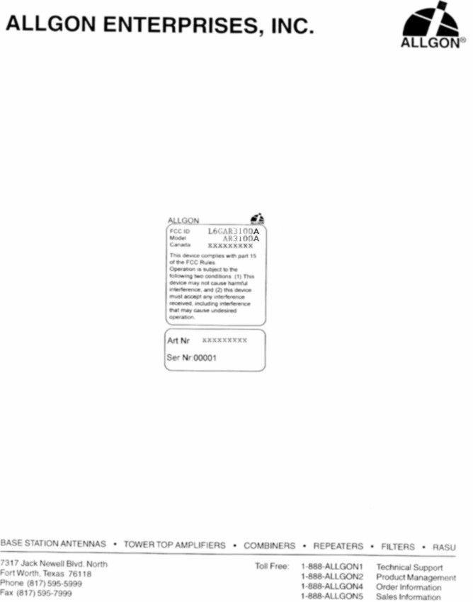
ALLGON ENTERPRISES, INC. BASE STATION ANTENNAS • TOWER TOP AMPLIFIERS • COMBINERS • REPEATERS • FILTERS • RASU 7317 Jack Newell Blvd. N.Toll Free: 1-888-ALLGON1 Fort Worth, Texas 76118 Phone (817)595-5999 Fax (817)595-7999 March 3,, 1999 Subject: Request for Confidentiality FCC ID: L6GAR3100A Gentlemen: In reference to Section 0.457(d) of the Commission’s Rules, and Section 552(b)(4) of the Freedom of Information Act, Allgon Enterprises, Inc. is requesting withholding from public information all schematics. The request for confidentiality is due to a very competitive market and necessity to keep proprietary design by Allgon Enterprises, Inc. intact. The requested schematics will be submitted in a package labeled as “Confidential”. Sincerely, Tim Purvis Product Engineer Allgon Enterprises, Inc. cc: Chris Harvey MET Laboratories Inc. 914 W. Patapsco Ave. Baltimore, MD 21230
Operational Description
ALLGON System AB AR Repeaters & OMTIntroduction Introduction Allgon repeaters are used to fill out uncovered areas in cellular mobile systems, such as base station fringe areas, road tunnels, busirEss and industrial buildings, etc. A repeater receives signals from a base station, amplifies and retransmits the signals to mobile stations. Also it receives, amplifies and retransmits signals in the opposite direction. Both directions are served simultaneously. To be able to receive and transmit signals in both directions, the repeater is connected to a donor antenna directed towards the base station and to a service antenna directed towards the area to be covered. Operation of the repeaters is performed using a desktop or notebook and the Allgon OMT (Operation & Maintenance Terminal) which communicate, locally or remotely via modem, with the repeaters. There is also an Allgon OMC (Operation & Maintenance Center), which is intended to be used to run many Allgon AR repeaters. The repeaters and the OMIT is described in this manual. The OMC is described in the Advanced Repeater 0MG, User’s Manual. User’s Manua~ VD2O1 17/EN Rev. 4B 19c8-03 2-1
Test Report
FCC ID: L6GAR3100A April 19, 1999 Federal Communications Commission Authorization and Evaluation Division 7435 Oakland Mills Road Columbia, MD 21046 Attention:Applications Examiner Applicant:Allgon Enterprises, Inc. 7317 Jack Newell Blvd. North Fort Worth, Texas 76118 Equipment:AMPS Cellular Repeater, Model: AR3100A FCC ID: L6GAR3100A Specification: 47 CFR 24 Licensed Certification Dear Examiner: The following application for Grant of Equipment Authorization is presented on behalf of Allgon Enterprises, Inc. for the Licensed Certification of their Model: AR3100A, PCS Cellular Repeater. Enclosed, please find a complete data and documentation package demonstrating that this device complies with the technical requirements of 47 CFR, Part 24, for a Cellular Repeater. If you have any questions, please contact the undersigned, who is authorized to act as Agent. Sincerely, Chris Harvey Director, EMC Laboratory FCC ID: L6GAR3100A EMI1186A- 2 -April 19, 1999 MET Laboratories, Inc. Safety Certification - EMI - Telecom Environmental Simulation 914 WEST PATAPSCO AVENUE • BALTIMORE, MARYLAND 21230-3432 • PHONE (410) 354-3300 • FAX (410) 354-3313 ENGINEERING TEST REPORT in support of the Application for Grant of Equipment Authorization EQUIPMENT: PCS Cellular Repeater, Model 3100A FCC ID:: L6GAR3100A Specification: 47 CFR 24 On Behalf of the Applicant: Allgon Enterprises, Inc. 7317 Jack Newell Blvd. North FortWorth, TX 76118 Manufacturer: Allgon Enterprises, Inc. 7317 Jack Newell Blvd. North FortWorth, TX 76118 Manufacturer’s Mr. Tim Purvis Representative Test Date(s): Mar 8 thru April 1, 1999 ENGINEERING STATEMENT I ATTEST: the measurements shown in this report were made in accordance with the procedures indicated, and that the emissions from this equipment were found to be within the limits applicable. I assume full responsibility for the accuracy and completeness of these measurements. On the basis of the measurements made, the equipment tested is capable of operation in accordance with the requirements of Part 24 of the FCC Rules under normal use and maintenance. _____________________________ Kenneth Bass EMI Engineer, MET Laboratories 1.0 1.01.0 1.0INTRODUCTION INTRODUCTIONINTRODUCTION INTRODUCTION FCC ID: L6GAR3100A EMI1186A- 3 -April 19, 1999 The following data is presented on behalf of the Applicant, Allgon Enterprises, Inc., as verification of the compliance of the Allgon PCS Cellular Repeater, Model 3100A to the requirements of 47CFR 24. 2.0 2.02.0 2.0TEST SITE TEST SITETEST SITE TEST SITE All testing was conducted at MET Laboratories, Inc., 914 West Patapsco Avenue, Baltimore, Maryland 21230-3493. Radiated emissions measurements were performed on a three-meter open area test site (OATS). A complete site description is on file with the FCC Laboratory Division as 31040/SIT/MET. 3.0 3.03.0 3.0TEST EQUIPMENT USED TEST EQUIPMENT USEDTEST EQUIPMENT USED TEST EQUIPMENT USED ManufacturerEquipment Calibration DueCal. Interval Hewlett Packard8563A Spectrum Analyzer5/22/99annual EMCOBiconical Antenna 31043/9/00annual EMCOEMCO Log Periodic Antenna2/16/00annual EMCODouble Ridge Guided Horn2/8/00annual Hewlett Packard8594EM Analyzer11/18/99annual Rhode & Swartz (X3)SMIQ 03 Digital Signal Gen.N/A (Verified using HP8563A)N/A SolarLISN6/30/99annual 4.0 4.04.0 4.0EQUIPMENT UNDER TEST CONFIGURATION EQUIPMENT UNDER TEST CONFIGURATIONEQUIPMENT UNDER TEST CONFIGURATION EQUIPMENT UNDER TEST CONFIGURATION The Cellular Repeater was configured with AC power supply modules and a digital signal generator was used to simulate various PCS (i.e. GMSK Modulation type) cellular RF input signals to the EUT. The EUT with host external computer was configured for maximum signal gain and bandwidth. The EUT was operated in a manner representative of the typical usage of the equipment. During all testing, (with the exception of intermodulation tests), the EUT was configured for Stacked Channel operation which results in maximum possible output gain. 5.0 5.05.0 5.0TEST TYPE(S) TEST TYPE(S)TEST TYPE(S) TEST TYPE(S) 5.1Radiated Emissions: 47CFR2.993, 24.238(a) 5.2Occupied Bandwidth: 47CFR2.989, Input vs. Output 5.3RF Power Output: 47CFR 2.985, 24.132(b),(c) 5.4Spurious Emission at Antenna Terminals:(uplink & downlink) 47CFR 2.991, 24.238(a) 5.5Intermodulation Spurious Emissions-2 Tone Simultaneous RF Injection (uplink & downlink): 47CFR2.991 , ,, , 24.238(a) 24.238(a)24.238(a) 24.238(a) 5.6Spurious Emission at Antenna Terminals +/- 1MHz: 47CFR 2.991, 24.238(b) 5.7AC Line Conducted Emissions: 47CFR 15.107 6.0TEST RESULTS FCC ID: L6GAR3100A EMI1186A- 4 -April 19, 1999 6.1TEST TYPE: Radiated Emissions 6.1.1 TECHNICAL SPECIFICATION: 2.993; 24.238(a) 6.1.2 TEST DATE(S): 1 April 1999 6.1.3 MEASUREMENT PROCEDURES: As required by §2.993, field strength of spurious radiation measurements were made in accordance with the general procedures of ANSI C63.4-1992 "Methods of Measurement of Radio- Noise Emissions from Low-Voltage Electrical and Electronic Equipment in the Range of 9kHz to 40 GHz". Preliminary radiated emission measurements were performed inside a shielded chamber with all digital signal generators on and terminated. The frequency list from the preliminary measurements was used as a guide for making final measurements on a 10 meter open area test site. The unit was scanned over the frequency range of 9 kHz to 20 GHz. The Radiated Spurious Emissions Limit is obtained by the following: Based on an output power (as measured at the output of the Amplifier) of 3 watts: P o = 3 W As per 2.993 (a), it is assumed this power is to be fed to a half-wave tuned dipole. Using a conversion formula for distance, the field strength at one meter can be derived: As per 24.238(a), the spurious emissions must be attenuated by 43 + log(P) which is: Therefore, the limit for spurious emissions is: At 3 meters measurement distance, the limit is; According to 24.238(a), all signals must be attenuated by 47.77 dB. Therefore, the limit for spurious emissions…
Text truncated - open the document above for the full version.
Contact Information
Applicant
Robert Biedka(Sr. Quality Engineer)
Technical Contact
MET Laboratories, Inc.Ken Bass
[email protected]410-354-3300
914 West Patapsco Ave. · Baltimore, Maryland · United States
Non-Technical Contact
MET Laboratories, Inc.Terri Wolf
[email protected]410-354-3300
Test Firm
MET Laboratories, Inc.John Mason
Technical Specifications
| # | Rule Parts | Frequency Range | Power Output | Emission | Tolerance |
|---|---|---|---|---|---|
| 2 | 24E | 1.93 GHz - 1.99 GHz | 8 W | EXTENDE | Amp |
Other Applications from Powerwave Technologies Inc.
L6GAR4540
Apr 10, 2001Channel Select9ive High-Power Repeater
Equipment Class
AMP - Amplifier
L6GAMR23-1200
Feb 01, 2001Microwave Point-to-Point Radio
Equipment Class
TNB - Licensed Non-Broadcast Station Transmitter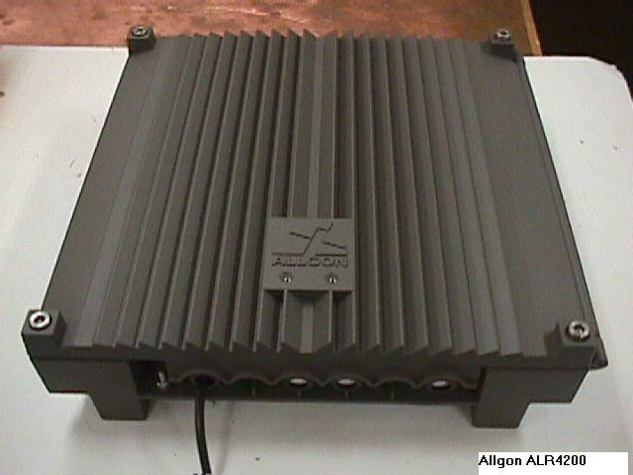
L6GALR4200
Oct 29, 2000Frequency Selective Repeater
Equipment Class
AMP - Amplifier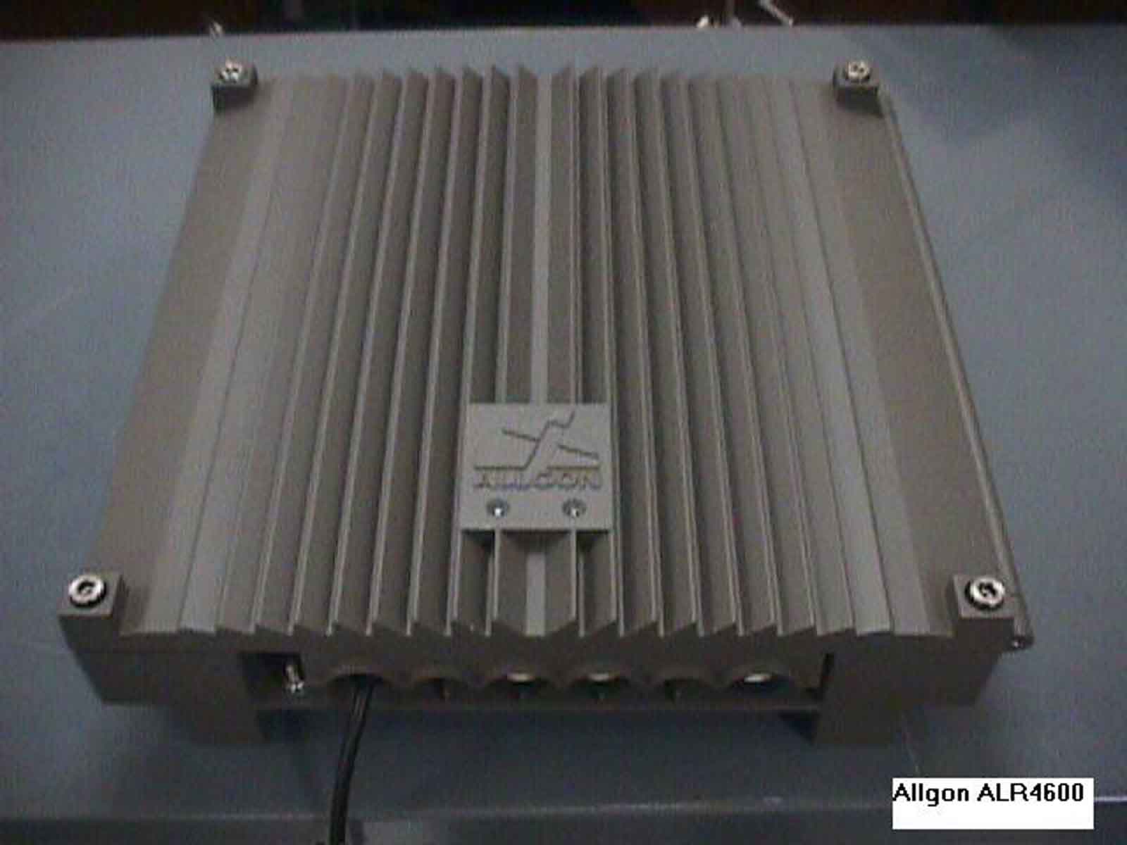
L6GALR4600
Oct 29, 2000Frequency Selective Repeater
Equipment Class
AMP - Amplifier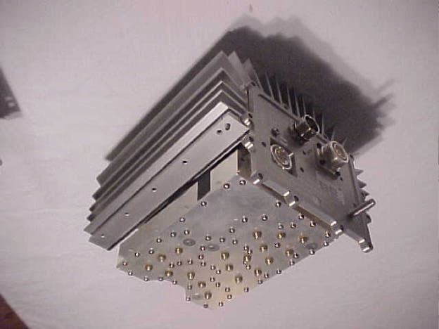
L6G922801
May 08, 2000Tower Top Power Apmilfier/Booster
Equipment Class
AMP - Amplifier