LCGFMR53XFluid Level Radar Transmitter
Endress and Hauser SE Co. KG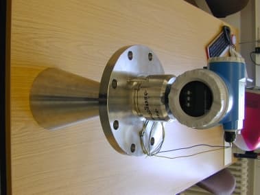
Click to zoom
Application Details
- Equipment Class
- DXX - Part 15 Low Power Communication Device Transmitter
- Date of Grant
- Jul 04, 2001
- Application Purpose
- Original Equipment
- Date of Application
- Aug 08, 2000
- Equipment Note
- Fluid Level Radar Transmitter
- Frequency Range
- 6300.00000000 - 6300.00000000
- Company
- Endress and Hauser SE Co. KG
- Country
- Germany
Documents & Files
Document Text
Text extracted from the exhibit documents filed with the FCC. Open a document above to read the original.
Users Manual
1Safety instructionsMicropilot S FMR 530 4Endress+Hauser 1Safety instructions 1.1Designated use The Micropilot S is a compact level transmitter designed for continuous, non-contact level measurement of liquids, pastes and slurries. The operating frequency of approx.6GHz lies in a frequency band approved for industrial use. Its low pulse power of 1mW (1mW ERP) allows safe installation in metallic and non-metallic vessels, with no risk to humans or the environment. 1.2Installation, commissioning and operation The Micropilot S has been designed to operate safely in accordance with current technical, safety and EU standards. If installed incorrectly or used for applications for which it is not intended, however, it is possible that application-related dangers may arise, e.g. product overflow due to incorrect installation or calibration. For this reason, the instrument must be installed, connected, operated and maintained according to the instructions in this manual: personnel must be authorised and suitably qualified. The manual must have been read and understood, and the instructions followed. Modifications and repairs to the device are permissible only when they are expressly approved in the manual. 1.3Operation safety Hazardous areas If the device is to be installed in an explosion hazardous area, then the specifications in the certificate as well as all national and local regulations must be observed. ∑Ensure that all personnel are suitably qualified. ∑Observe the specifications in the certificate as well as national and local regulations. FCC approval This device complies with part 15 of the FCC Rules. Operation is subject to the following two conditions: (1) This device may not cause harmful interference, and (2) this device must accept any interference received, including interference that may cause undesired operation. Α Caution! Changes or modifications not expressly approved by the part responsible for compliance could void the user’s authority to operate the equipment. 1Safety instructionsMicropilot S FMR 531 4Endress+Hauser 1Safety instructions 1.1Designated use The Micropilot S is a compact level transmitter designed for continuous, non-contact level measurement of liquids, pastes and slurries. The operating frequency of approx.6GHz lies in a frequency band approved for industrial use. Its low pulse power of 1mW (1mW ERP) allows safe installation in metallic and non-metallic vessels, with no risk to humans or the environment. 1.2Installation, commissioning and operation The Micropilot S has been designed to operate safely in accordance with current technical, safety and EU standards. If installed incorrectly or used for applications for which it is not intended, however, it is possible that application-related dangers may arise, e.g. product overflow due to incorrect installation or calibration. For this reason, the instrument must be installed, connected, operated and maintained according to the instructions in this manual: personnel must be authorised and suitably qualified. The manual must have been read and understood, and the instructions followed. Modifications and repairs to the device are permissible only when they are expressly approved in the manual. 1.3Operation safety Hazardous areas If the device is to be installed in an explosion hazardous area, then the specifications in the certificate as well as all national and local regulations must be observed. ∑Ensure that all personnel are suitably qualified. ∑Observe the specifications in the certificate as well as national and local regulations. FCC approval This device complies with part 15 of the FCC Rules. Operation is subject to the following two conditions: (1) This device may not cause harmful interference, and (2) this device must accept any interference received, including interference that may cause undesired operation. Α Caution! Changes or modifications not expressly approved by the part responsible for compliance could void the user’s authority to operate the equipment. 1Safety instructionsMicropilot S FMR 532 4Endress+Hauser 1Safety instructions 1.1Designated use The Micropilot S is a compact level transmitter designed for continuous, non-contact level measurement of liquids, pastes and slurries. The operating frequency of approx.6GHz lies in a frequency band approved for industrial use. Its low pulse power of 1mW (1mW ERP) allows safe installation in metallic and non-metallic vessels, with no risk to humans or the environment. 1.2Installation, commissioning and operation The Micropilot S has been designed to operate safely in accordance with current technical, safety and EU standards. If installed incorrectly or used for applications for which it is not intended, however, it is possible that application-related dangers may arise, e.g. product overflow due to incorrect installation or calibration. For this reason, the instrument must be installed, connected, operated and maintained according to the instructions in this manual: personnel must be authorised and suitably qualified. The manual must have been read and understood, and the instructions followed. Modifications and repairs to the device are permissible only when they are expressly approved in the manual. 1.3Operation safety Hazardous areas If the device is to be installed in an explosion hazardous area, then the specifications in the certificate as well as all national and local regulations must be observed. ∑Ensure that all personnel are suitably qualified. ∑Observe the specifications in the certificate as well as national and local regulations. FCC approval This device complies with part 15 of the FCC Rules. Operation is subject to the following two conditions: (1) This device may not cause harmful interference, and (2) this device must accept any interference received, including interference that may cause undesired operation. Α Caution! Changes or modifications not expressly approved by the part responsible for compliance could void the user’s aut…
Text truncated - open the document above for the full version.
Cover Letter(s)
'll ~ e6ed JeJeol)i Je~ed "A"! .1-~'l JeuunJqeu!e~s .3 .'v'.! J-?~ -/~3 OOOl'lnr 'L \' . 6Jn~new6996L -0 1.9 ~ I. ltoe"sod " &"eJ~s~dneH 0:) + Hqw~ JesneH + sseJpu3 uep '6JnqlnelN .SJOI!ladwo~ WOJJ papJen5 aq PlnoLIs sluawn~op aLIlleLlI'uo paseq S! AI!le!IUap!Juo~ JoJ ISanbaJ aLIl. "5u!IS!1 paLl~e»e aLlI U! UMOLIS se sluawn~op pawwqns aLlI Jo AI!le!IUap!Juo~ JoJ s)jse JasneH + ssaJpu3 AuewJeE) 6Jnqlnell'J 6996L -0 ~ esseJ~s~dneH "oJ + Hqwf) JesneH + sseJpu3 :eeJueJ6 Ja eweN XE9~lAJ::19~l 01 ~~.::1 xE9 ~V'J.::1 S ~OI!doJ~!V'J JO~ Xf;9CJI/\J.::1~~1 01 ~~.::1 X9 HlI'J::1lOI!doJ~!lI'JAl!le!lUep!~uo~ JO~ lsenbeH Micropilot FMR 53x FCC 10 LCGFMR53X Request tor Contidentiality Documents under confidentiatility page 2 / 2
External Photos
FCC ID: LCGFMR53X, External Photos
Internal Photos
FCC ID: LCGFMR53X, Internal Photos
Operational Description
Description Micropilot S FMR 53x docu:Tech_Descr_FMR53x_FCC.doc Dep. : LCName: E. SteinebrunnerV1.0Date: 14.07.00page 1/2 ManufacturerEndress +Hauser GmbH+Co. Hauptstr. 1 D 79689 Maulburg Germany Types Micropilot S FMR53x series- with Radar Module II.2 FCC IDLCGFMR53X Task The Radar Modules will be deployed in compact level transmitters for continuous non- contact measurement of liquids in vessels and tanks. Short microwave pulses were sent from the antenna, reflected at the surface of the material and received from the antenna. The time between transmitting and receiving will be evaluated and calculated to an adequate level signal. Because the velocity of light waves is nearly independent of temperature, pressure and humidity, these new radar technologies offer new applications for level measurement under the rough conditions in the industry. Instrument assembly The modules are deployed in microwave product families (e.g. Micropilot S FMR53x, of radar level transmitters of Endress + Hauser GmbH + Co. in combination with different types of antennas like horn or rod antennas. All product families comprise different variants, which can be different from housing, evaluation electronic with signal processing or communication protocol. The microwave performance, however, is fixed by the module itself so that the transmitted microwave power depends only on the gain of the antenna. System description of the emitting / receipt part: The RADAR Module consists of two parts: 1)The scanning frequency processing 2)The pulse generator The output signal of part 1) triggers the generation and emission of the emitting microwave pulse in part 2). The scanning frequency processing also triggers an internal microwave pulse within the module. The trigger signal for the internal pulse is delayed in dependence on time compared to the emitted pulse, so that the receiving pulse reflected by the level will be scanned by this internal pulse. Both signals are fed to an mixer and result in an IF signal. This technique causes a time conversion from the nanosecond range of the HF signal to the millisecond range of the IF signal, enabling the possibility that the signal processing can be performed by low cost standard semiconductor electronic. The pulse generator emits extreme short pulses of approx. 1.2 ns, which therefore correspond with a bandwidth of approx. ± 0.83 GHz. This short pulses are required to get an appropriate accuracy and resolution for the level measurement. The pulses comprises a few oscillations and result together with all possible tolerances in the listed values for the spread spectrum. Description Micropilot S FMR 53x docu:Tech_Descr_FMR53x_FCC.doc Dep. : LCName: E. SteinebrunnerV1.0Date: 14.07.00page 2/2 This scanning principle is comparable with the correlation principle and therefore results in a powerful filter effect. In this way even extreme low power emitted pulses are sufficient for the level measurement with high accuracy. Summary of the electrical characteristics values of the S / E part: Emitting frequency6.3GHz Emission pulse clock frequency3.579545MHz Scanning pulse clock frequency3.57952315MHz Frame frequency of the PN-generator27.96kHz Emitting pulse with 6 dB app.1.2ns Emitting pulse peak envelope power< -9dBm Antenna gain< 24dBi Calculation of pulse spectrum: f centre = 6.3GHzcentre frequency T pulse = 1.2 nsecpulse length B = 2/T pulse band width f min = f centre - 1/T pulse = 6.3 GHz- 0.83 GHz = 5.47 GHz = >5.46 GHz Assembly: A Radar Module II.2 consists of a multilayer printed circuit board built in a plastic housing. The surface of the housing is electrically conductive. One face of the printed circuit board of the Radar Module II.2 is the HF Front end according to the schematic 960402-3057 called “Radar- Module II.2”; the other face of the printed circuit board contains the frequency treatment stage according to the schematic 960402-3056 called “Radar Module II.x frequency excitation”. Inputs / Outputs: The electrical connection from the Radar Module II.2 to the evaluation stage of the Micropilot FMR53x is made via connector. The Radar Module has following input / output ports ( see drawing n° 960402-3056 / -3057): - Supply - Standby input - Intermediate frequency output - Trigger output signal - GND The microwave signals are led to the antenna systems of the Micropilot series by a coaxial cable. Operating data: Supply voltage.3,5V
Test Report
FCC-ID: LCGFMR53XTest Report No. 50511-00331 Page 1 of 68 Pages Straubing, August 02, 2000 T E S T - R E P O R T No. 50511-00331 for Micropilot S FMR 53X Fluid Level Measuring Transmitter (with Rod and Horn Antennas) Applicant:Endress + Hauser GmbH & Co. Purpose of testing:To show compliance with FCC Code of Federal Regulations, CFR 47, Part 15, Subpart C, Sections 15.207 and 15.209 Note: The test data of this report relate only to the individual item which has been tested. This report shall not be reproduced except in full extent without the written approval of the testing laboratory. FCC-ID: LCGFMR53XTest Report No. 50511-00331 Page 2 of 68 Pages Table of Contents 1.Administrative Data3 2.Summary of Test Results4 3.Operation Mode of EUT5 4.Changes made to the EUT during this certification test5 5.Configuration of EUT and Peripheral Devices5 6.Measuring Methods6 7.Photographs Taken During Testing12 8.List of Measurements15 9.Test Results16 10. Equipment List19 11. Charts Taken During Testing23 FCC-ID: LCGFMR53XTest Report No. 50511-00331 Page 3 of 68 Pages 1.Administrative Data Equipment Under Test (EUT): FMR 53X Type of equipment:Fluid Level Measuring Transmitter Parts/accessories:N.A. Version of EUT:The following versions of the EUT have been tested: - FMR 530 with Horn Antenna - FMR 531 with PTFE Rod antenna - FMR 532 with Planar Antenna - FMR 533 with Parabolic Antenna FCC-ID:LCGFMR53X Applicant:Endress + Hauser GmbH + Co. (full address)Hauptstrasse 1 D-79689 Maulburg Contract identification:007/00300647 Contact person:Mr. Peter Klöfer Manufacturer:Applicant Receipt of EUT:June 06, 2000 Date of test:June 06, 2000 Note: All tests were performed under normal installation conditions with the EUT installed in several tanks. Since it was not possible to transport the tanks used for testing to an open field test site, testing was performed at the mentioned factories: • Plastic tank at Photo Print Electronic in D-79690 Schopfheim • Concrete tank with open roof and windows at concrete factory Schweigert in D-79689 Maulburg • Glass container and metallic tank at applicant ́s factory in D-79689 Maulburg Responsible for testing:Mr. Johann Roidt Responsible for test report:Mr. Johann Roidt FCC-ID: LCGFMR53XTest Report No. 50511-00331 Page 4 of 68 Pages 2.Summary of Test Results The tested samples fully comply with the requirements for intentional radiators set forth in the Code of Federal Regulations CFR 47 Part 15 Subpart C, Sections 15.207 and 15.209 of the Federal Communication Commission (FCC). Johann Roidt Technical Manager FCC-ID: LCGFMR53XTest Report No. 50511-00331 Page 5 of 68 Pages 3.Operation Mode of EUT The EUT was powered from a 18 V DC power source. During all measurements the EUT was set to normal measuring mode. During all measurements the EUT was placed vertically in non-metallic tanks. The following applications were investigated in detail: • EUT with Horn antenna • EUT with Rod antenna. • Applications in a plastic tank (fig. 1) • Applications in a concrete tank with windows (fig. 2), • Applications in a glass tank (fig.3) 4.Changes made to the EUT during this certification test No changes have been made to the EUT during this certification test. 5.Configuration of EUT and Peripheral Devices Configuration of cables to EUT Unshielded two-wire power supply cable Configuration of peripheral devices connected to EUT Not applicable FCC-ID: LCGFMR53XTest Report No. 50511-00331 Page 6 of 68 Pages 6.Measuring Methods 6.1.Radiated Emissions above 1 GHz Radiated emissions were measured in the frequency range 5 GHz to 8 GHz in transmit mode of the EUT. The resolution bandwidth and the video bandwidth of the spectrum analyzer were set to 1 MHz, the sweep-time to 20 ms. Since the EUT is a pulsed system with a duty cycle < 1:100, a desensitization factor of > 40 dB had to be expected. Analyzer readings of emissons at the limit for peak emissions at 3 meter distance would be approximately – 4 dBμV. The noise level of our very sensitive spectrum analyzer (ESMI, Rohde & Schwarz) plus a 40 dB preamplifier is approximately 5 dBμV. The only way to achieve sufficient dynamic range is to reduce test distance. For the measurement described in this report, the test distance was reduced to 0.3 meter. test-distance 0.3 meters Measuring antenna Spectrumanalyzer Preamplifier EUT plastic tank 1 m 3 m 1.7 m (3 mm Polyethylen) fig.1 application in plastic tank FCC-ID: LCGFMR53XTest Report No. 50511-00331 Page 7 of 68 Pages test-distance 0.3 meters Measuring antenna Spectrumanalyzer Preamplifier concrete tank (10 cm concrete) windows 2,4 m 2 m EUT fig.2 application in a concrete tank test-distance 0.3 meters Measuring antenna Spectrumanalyzer Preamplifier EUT 1,60 m 30 cm Glas tank fig.3 application in a glass tank FCC-ID: LCGFMR53XTest Report No. 50511-00331 Page 8 of 68 Pages 6.2.Procedure for Preliminary Radiated Emission Tests The procedure for preliminary radiated emission tests was based on section 13.4.1 of ANSI C63.4-1992. The EUT was mounted in its normal operation condition on the tanks. Prescans are made in the frequency ranges: 4 GHz - 8 GHz with the receiving antenna set to horizontal and vertical polarization. The following step-by-step procedure was used: 1) Monitor the frequency range with the antenna at 30 cm distance to the EUT, all venting openings as well as other locations on which radiation might be detected. 2)Move the antenna while maintaining the test distance to detect maximum radiation. 3)Make a hardcopy of the spectrum. 4)Repeat steps 1 through 3 for orthogonal antenna polarisation FCC-ID: LCGFMR53XTest Report No. 50511-00331 Page 9 of 68 Pages 6.2.1.Method for comparing spectrum analyzer output to the limit The following procedure will be used: 1)Maximize the emission according to 6.2. 2)Set the spectrum analyzer to Max Hold 3)Wait until the noise is fully maximized. 4)Put the marker on top of the investigated signal 5) Note frequency and level of the investigated signal 6.3.Spec…
Text truncated - open the document above for the full version.
Contact Information
Applicant
Ralf Reimelt(R&D Radar Level Measurement)
Technical Contact
Senton GmbHJohann Roidt
[email protected]+49 9421 55 22 13
Aeussere Fruehlingstrasse 45 · Straubing · Germany
Non-Technical Contact
Senton GmbHJohann Roidt
[email protected]+49 9421 55 22 13
Test Firm
TUV SUD Product Service GmbH PS-EMC-STRRainer Heller
Technical Specifications
| # | Rule Parts | Frequency Range | Power Output | Tolerance |
|---|---|---|---|---|
| 1 | 15C | 6.30 GHz - 6.30 GHz | - | % |
Other Applications from Endress and Hauser SE Co. KG
LCGFMI43
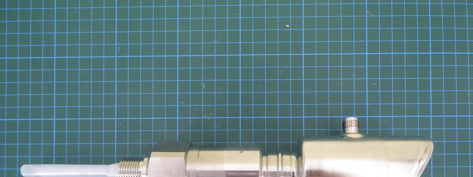
Jul 29, 2026Capacitive level sensor with BLE communication
Equipment Class
DTS - Digital Transmission System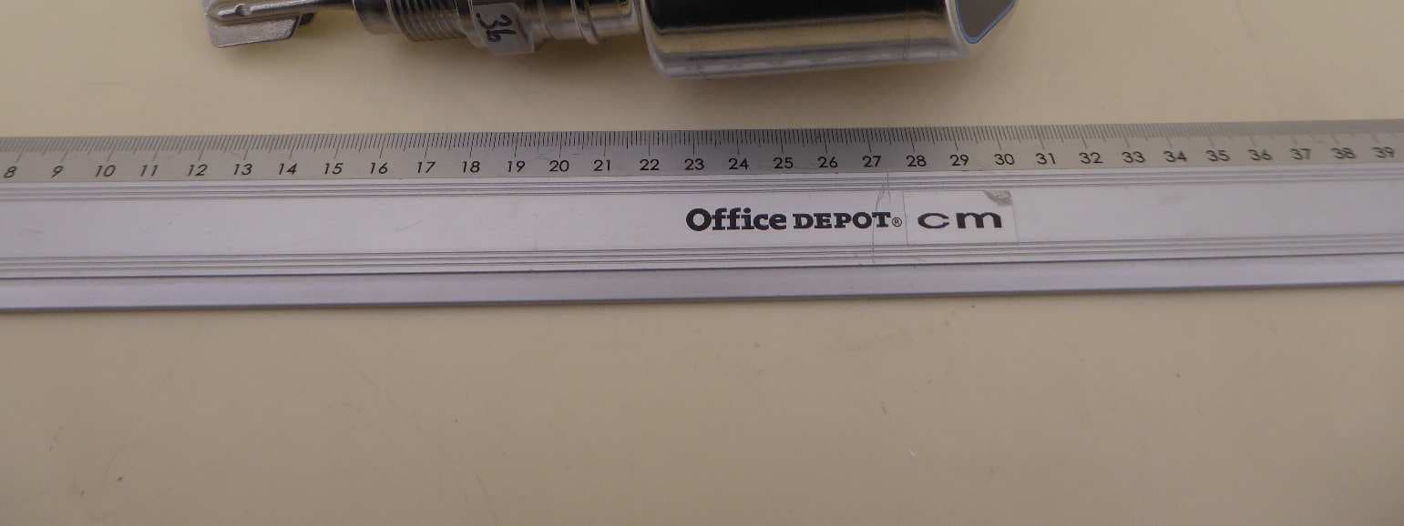
LCGFTL4X
Nov 28, 2024Hygienic point level switch for liquids with BLE TX
Equipment Class
DTS - Digital Transmission System
LCGFMR43L
Aug 07, 2024Level Probing Radar
Equipment Class
DXX - Part 15 Low Power Communication Device Transmitter
LCGUXR3XYEL
Oct 29, 2023Level Probing Radar
Equipment Class
LPR - Level Probing Radar
LCGFWR3XWEL
May 18, 2020Level Probing Radar
Equipment Class
LPR - Level Probing Radar