LCGFMR5XKLevel Radar
Endress and Hauser SE Co. KG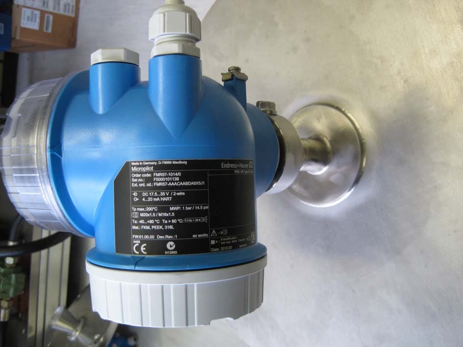
Click to zoom
Application Details
- Equipment Class
- DXX - Part 15 Low Power Communication Device Transmitter
- Date of Grant
- Sep 11, 2013
- Application Purpose
- Original Equipment
- Date of Application
- Sep 11, 2013
- Equipment Note
- Level Radar
- Frequency Range
- 25200.00000000 - 25200.00000000
- Company
- Endress and Hauser SE Co. KG
- Country
- Germany
Documents & Files
Document Text
Text extracted from the exhibit documents filed with the FCC. Open a document above to read the original.
Users Manual
D R A F T Application Continuous, non-contact level measurement of liquids, pastes and slurries Features FMR50 • Attractively-priced device for basic supply and storage applications as well as utility processes • Encapsulated PVDF or PP cladded horn antenna • Maximum measuring range: 30 m (98 ft); for version with enhanced dynamics: 40 m (131 ft) • Process connection : 1½" thread , mounting bracket or with slip-on flange • Temp. range: –40 to +130 °C (–40 to +266 °F) • Pressure range: –1 to +3 bar (–14.5 to +43.5 psi) • Accuracy: ± 2 mm Your benefits • Reliable measurement even for changing product and process conditions • Integrated data memory (HistoROM) for high availability • Intuitive operating menu in national languages for easy commissioning • Simple integration into control or asset management systems • Exact diagnostic and process information to assist fast decisions • International approvals for use in hazardous areas • 5-point linearity protocol • WHG and marine approvals • SIL2 according to IEC 61508, SIL3 in case of homogeneous or heterogeneous redundancy • System integration via HART/PROFIBUS PA (Profile 3.02)/FOUNDATION Fieldbus Technical Information Micropilot FMR50 Level radar Level measurement in liquids TI01039F/00/EN/01.12 71162666 D R A F T Table of contents Micropilot FMR50 2V. 1, Rev. 6, 4-10-2012Endress+Hauser Table of contents Important document information................3 Document conventions...........................3 Function and system design....................5 Measuring principle.............................5 Input.....................................7 Measured variable..............................7 Measuring range...............................7 Operating frequency............................10 Transmitting power............................10 Output...................................11 Output signal................................11 Signal on alarm...............................12 Linearization................................12 Galvanic isolation.............................12 Protocol-specific data...........................12 Power supply.............................16 Terminal assignment...........................16 Device plug connectors..........................23 Supply voltage...............................24 Power consumption............................26 Current consumption...........................26 Power supply failure............................27 Potential equalization...........................27 Terminals..................................27 Cable entries ................................27 Cable specification.............................27 Overvoltage protection..........................28 Performance characteristics...................29 Reference operating conditions.....................29 Maximum measured error........................29 Measured value resolution........................30 Reaction time................................30 Influence of ambient temperature...................30 Installation...............................31 Installation conditions...........................31 Measuring conditions...........................35 Installation in vessel (free space)....................36 Installation in stilling well........................39 Installation in bypass...........................42 Vessels with heat insulation.......................45 Environment..............................46 Ambient temperature range.......................46 Ambient temperature limits.......................46 Storage temperature............................47 Climate class................................47 Geometric height according to IEC61010-1 Ed.3..........47 Degree of protection............................47 Vibration resistance............................47 Cleaning the antenna...........................47 Electromagnetic compatibility (EMC).................48 Process..................................49 Process temperature range........................49 Process pressure range..........................49 Dielectric constant.............................49 Mechanical construction.....................50 Dimensions.................................50 Weight....................................53 Materials...................................53 Operability...............................57 Operating concept.............................57 Local operation...............................57 Operation with remote display and operating module FHX50..58 Remote operation.............................58 Integration in tank gauging system...................62 System integration via Fieldgate.....................63 Certificates and approvals....................64 CE mark...................................64 C-Tick symbol...............................64 Ex approval.................................64 Dual seal according to ANSI/ISA 12.27.01..............64 Functional Safety..............................64 Pressure Equipment Directive......................64 Marine certificate (in preparation)...................64 Radio standard EN302729-1/2.....................64 Radio standard EN302372-1/2.....................65 FCC / Industry Canada..........................65 CRN approval................................66 Track record................................66 Other standards and guidelines .....................66 Ordering information........................67 Ordering information...........................67 5-point linearity protocol (in preparation)...............67 Customized parametrization.......................68 Accessories...............................69 Device-specific accessories........................69 Communication-specific accessories..................72 Service-specific accessories........................73 System components............................73 Documentation............................74 Standard documentation.........................74 Supplementary documentation.....................74 Safety Instructions (XA)..........................74 Register…
Text truncated - open the document above for the full version.
Users Manual
D R A F T Application Continuous, non-contact level measurement of liquids, pastes and slurries Features FMR51: • Premium device for level measurements even under extreme conditions • Maximum measuring range: 40 m (131 ft); for version with enhanced dynamics: 70 m (230 ft) • Process connection: 1½" thread/Tri-Clamp/flange • Temp. range: –196 to +450 °C (–321 to +842 °F) • Pressure range: –1 to +160 bar (–14.5 to +2 320 psi) • Accuracy: ± 2 mm Features FMR52: • Premium device for aggressive media as well as for highest hygiene requirements (ASME BPE, USP Class VI) • Flush mounted, completely filled PTFE horn antenna • Maximum measuring range: 40 m (131 ft); for version with enhanced dynamics: 60 m (197 ft) • Process connection: Flush mounted with cladded flange; process connections for hygiene requirements (Tri-Clamp, DIN 11851) • Temp. range: –40 to +200 °C (–40 to +392 °F) • Pressure range: –1 to +16 bar (–14.5 to +232 psi) • Accuracy: ± 2 mm Your benefits • Reliable measurement even for changing product and process conditions • Integrated data memory (HistoROM) for high availability • Intuitive operating menu in national languages for easy commissioning • Simple integration into control or asset management systems • Exact diagnostic and process information to assist fast decisions • International approvals for use in hazardous areas • 5-point linearity protocol • WHG and marine approvals • SIL2 according to IEC 61508, SIL3 in case of homogeneous or heterogeneous redundancy • System integration via HART/PROFIBUS PA (Profile 3.02)/FOUNDATION Fieldbus Technical Information Micropilot FMR51, FMR52 Level radar Level measurement in liquids TI01040F/00/EN/01.12 71162672 D R A F T Table of contents Micropilot FMR51, FMR52 2V. 1, Rev. 8, 4-10-2012Endress+Hauser Table of contents Important document information................4 Document conventions...........................4 Function and system design....................6 Measuring principle.............................6 Input.....................................8 Measured variable..............................8 Measuring range...............................8 Operating frequency............................13 Transmitting power............................13 Output...................................14 Output signal................................14 Signal on alarm...............................15 Linearization................................15 Galvanic isolation.............................15 Protocol-specific data...........................15 Power supply.............................19 Terminal assignment...........................19 Device plug connectors..........................26 Supply voltage...............................27 Power consumption............................29 Current consumption...........................29 Power supply failure............................30 Potential equalization...........................30 Terminals..................................30 Cable entries ................................30 Cable specification.............................30 Overvoltage protection..........................31 Performance characteristics...................32 Reference operating conditions.....................32 Maximum measured error........................32 Measured value resolution........................33 Reaction time................................33 Influence of ambient temperature...................33 Influence of gas layer...........................33 Gas phase compensation with external pressure sensor (PROFIBUS PA, in preparation).....................34 Installation...............................35 Installation conditions...........................35 Measuring conditions...........................40 Installation in vessel (free space)....................41 Installation in stilling well........................44 Installation in bypass...........................47 Vessels with heat insulation.......................50 Environment..............................51 Ambient temperature range.......................51 Ambient temperature limits.......................51 Storage temperature............................58 Climate class................................58 Geometric height according to IEC61010-1 Ed.3..........59 Degree of protection............................59 Vibration resistance............................59 Cleaning the antenna...........................59 Electromagnetic compatibility (EMC).................59 Process..................................60 Process temperature range........................60 Process pressure range..........................60 Dielectric constant.............................60 Mechanical construction.....................61 Dimensions.................................61 Weight....................................66 Materials...................................66 Operability...............................71 Operating concept.............................71 Local operation...............................71 Operation with remote display and operating module FHX50..72 Remote operation.............................72 Integration in tank gauging system...................76 System integration via Fieldgate.....................77 Certificates and approvals....................78 CE mark...................................78 C-Tick symbol...............................78 Ex approval.................................78 Dual seal according to ANSI/ISA 12.27.01..............78 Functional Safety..............................78 Sanitary compatibility...........................78 AD2000...................................78 Pressure Equipment Directive......................78 Marine certificate (in preparation)...................78 Radio standard EN302729-1/2.....................78 Radio standard EN302372-1/2.....................79 FCC / Industry Canada..........................79 CRN approval................................80 Track record................................80 Other standards and guidelines ..............…
Text truncated - open the document above for the full version.
Users Manual
D R A F T Application Continuous, non-contact level measurement in powdery to granular bulk solids Features FMR56: • Attractively-priced basic device for standard process conditions, as for example in bulk cargo silos and storage tanks • PP-cladded horn antenna • Maximum measuring range: 30 m (98 ft) • Process connection: Mounting bracket or slip-on flange with variable flange seal for alignment • Temperature range: –40 to +80 °C (–40 to 176 °F) • Pressure range: –1 to +3 bar (–14.5 to +43.5 psi) • Accuracy: ± 3 mm Features FMR57: • Premium device for highly demanding solid applications; ideally suited for measurements in high silos, bunkers and stockpiles • Horn or parabolic antenna • Air purge connection integrated • Maximum measuring range: 70 m (230 ft) • Process connection: 1½" thread or flange • Temperature range: –40 to +400 °C (–40 to 752 °F) • Pressure range: –1 to +16 bar (–14.5 to +232 psi) • Accuracy: ± 3 mm Your benefits • Reliable measurement even for changing product and process conditions • Integrated data memory (HistoROM) for high availability • Intuitive operating menu in national languages for easy commissioning • Simple integration into control or asset management systems • Exact diagnostic and process information to assist fast decisions • International approvals for use in hazardous areas • 5-point linearity protocol • SIL2 according to IEC 61508, SIL3 in case of homogeneous or heterogeneous redundancy • System integration via HART/PROFIBUS PA (Profile 3.02)/FOUNDATION Fieldbus Technical Information Micropilot FMR56, FMR57 Level radar Level measurement in bulk solids TI01042F/00/EN/01.12 71162681 D R A F T Table of contents Micropilot FMR56, FMR57 2V. 1, Rev. 6, 19-10-2012Endress+Hauser Table of contents Important document information................3 Document conventions...........................3 Function and system design....................5 Measuring principle.............................5 Input.....................................7 Measured variable..............................7 Measuring range...............................7 Operating frequency............................8 Transmitting power.............................8 Output....................................9 Output signal.................................9 Signal on alarm...............................10 Linearization................................10 Galvanic isolation.............................10 Protocol-specific data...........................10 Power supply.............................14 Terminal assignment...........................14 Device plug connectors..........................21 Supply voltage...............................22 Power consumption............................24 Current consumption...........................24 Power supply failure............................25 Potential equalization...........................25 Terminals..................................25 Cable entries ................................25 Cable specification.............................25 Overvoltage protection..........................26 Performance characteristics...................27 Reference operating conditions.....................27 Maximum measured error........................27 Measured value resolution........................27 Reaction time................................28 Influence of ambient temperature...................28 Installation...............................29 Installation conditions...........................29 Measuring conditions...........................36 Installation in vessel (free space)....................37 Vessels with heat insulation.......................46 Environment..............................47 Ambient temperature range.......................47 Ambient temperature limits.......................47 Storage temperature............................51 Climate class................................51 Geometric height according to IEC61010-1 Ed.3..........51 Degree of protection............................51 Vibration resistance............................51 Cleaning the antenna...........................51 Electromagnetic compatibility (EMC).................52 Process ..................................53 Process temperature range........................53 Process pressure range..........................53 Dielectric constant.............................53 Mechanical construction.....................54 Dimensions.................................54 Weight....................................61 Materials...................................62 Operability...............................67 Operating concept.............................67 Local operation...............................67 Operation with remote display and operating module FHX50..68 Remote operation.............................68 System integration via Fieldgate.....................72 Certificates and approvals....................73 CE mark...................................73 C-Tick symbol...............................73 Ex approval.................................73 Dual seal according to ANSI/ISA 12.27.01..............73 Functional Safety..............................73 AD2000...................................73 Pressure Equipment Directive......................73 Marine certificate (in preparation)...................73 Radio standard EN302729-1/2.....................73 Radio standard EN302372-1/2.....................74 FCC / Industry Canada..........................74 CRN approval................................75 Track record................................75 Other standards and guidelines .....................75 Ordering information........................76 Ordering information...........................76 5-point linearity protocol (in preparation)...............76 Customized parametrization.......................77 Accessories...............................78 Device-specific accessories........................78 Communication-specific accessories..................81 Service-specific accessories..................…
Text truncated - open the document above for the full version.
External Photos
FCC ID LCGFMR5XK IC: 2519A-5K K1 liquid FCC ID LCGFMR5XK IC: 2519A-5K K1 liquid FCC ID LCGFMR5XK IC: 2519A-5K K1 liquid FCC ID LCGFMR5XK IC: 2519A-5K K1 liquid FCC ID LCGFMR5XK IC: 2519A-5K K1 liquid FCC ID LCGFMR5XK IC: 2519A-5K K1 liquid FCC ID LCGFMR5XK IC: 2519A-5K K2 liquid FCC ID LCGFMR5XK IC: 2519A-5K K2 liquid FCC ID LCGFMR5XK IC: 2519A-5K K2 liquid FCC ID LCGFMR5XK IC: 2519A-5K K2 liquid FCC ID LCGFMR5XK IC: 2519A-5K K2 liquid FCC ID LCGFMR5XK IC: 2519A-5K K3 liquid FCC ID LCGFMR5XK IC: 2519A-5K K3 liquid FCC ID LCGFMR5XK IC: 2519A-5K K3 liquid FCC ID LCGFMR5XK IC: 2519A-5K K3 liquid FCC ID LCGFMR5XK IC: 2519A-5K K3 liquid FCC ID LCGFMR5XK IC: 2519A-5K K4 liquid FCC ID LCGFMR5XK IC: 2519A-5K K4 liquid FCC ID LCGFMR5XK IC: 2519A-5K K4 liquid FCC ID LCGFMR5XK IC: 2519A-5K K4 liquid FCC ID LCGFMR5XK IC: 2519A-5K K4 liquid FCC ID LCGFMR5XK IC: 2519A-5K K4 liquid FCC ID LCGFMR5XK IC: 2519A-5K K5 solid FCC ID LCGFMR5XK IC: 2519A-5K K5 solid FCC ID LCGFMR5XK IC: 2519A-5K K5 solid FCC ID LCGFMR5XK IC: 2519A-5K K5 solid FCC ID LCGFMR5XK IC: 2519A-5K K5 solid FCC ID LCGFMR5XK IC: 2519A-5K K5 solid FCC ID LCGFMR5XK IC: 2519A-5K K6 solid FCC ID LCGFMR5XK IC: 2519A-5K K6 solid FCC ID LCGFMR5XK IC: 2519A-5K K6 solid FCC ID LCGFMR5XK IC: 2519A-5K K6 solid FCC ID LCGFMR5XK IC: 2519A-5K K6 solid
ID Label/Location Info
Ext. ord. cd.: Ext. ord. cd.: Order code: Order code: Ser. no.: Ser. no.: Made in Germany, 79689 Maulburg Made in Germany, 79689 Maulburg Micropilot Micropilot Ex i Ex i Ex i Ex i Ex d Ex d or or Compartment Compartment FMR50-01234567890123 FMR50-01234567890123 012345678901234567890123456789012 012345678901234567890123456789012 Tp max: Tp max: FOUNDATION Fieldbus FOUNDATION Fieldbus Switch output Switch output MWP: 1 bar / 14.5 psi MWP: 1 bar / 14.5 psi LN = 550mm LN = 550mm 150°C 150°C Mat.: Graphite,AL2O3,316L Mat.: Graphite,AL2O3,316L Date: Date: 250002991-- 250002991-- IP68 / 66 Type 4X / 6P Encl. IP68 / 66 Type 4X / 6P Encl. Dual seal (MWP: 370bar) Dual seal (MWP: 370bar) Z-65.16-354 Z-65.16-354 96000xxxx-- 96000xxxx-- 96000xxxx-- 96000xxxx-- 96000xxxx-- 96000xxxx-- 96000xxxx-- 96000xxxx-- 2010-03 2010-03 WARNING - Potential electrostatic WARNING - Potential electrostatic FISCO FISCO M20x1.5 / M16x1.5 M20x1.5 / M16x1.5 FW: 01.00.00 FW: 01.00.00 Dev.Rev.: 1 Dev.Rev.: 1 ex works ex works DeviceID: DeviceID: Ta > 60 °C: Ta>60°C: Ta: -40...+80 °C Ta: -40...+80 °C 452B481005-A91234010AB 452B481005-A91234010AB 12345678901234 12345678901234 12345678901234 12345678901234 05000195 05000195 if modification see sep. label X= if modification see sep. label X= charging harzard - see instructions charging harzard - see instructions FCC ID LCGFMR5XK FCC ID LCGFMR5XC N12895 N12895 0700 0700 IS CL I, DIV 1, GP A - D IS CL I, DIV 1, GP A - D Ext.ord.cd.: Order code: Ser. no.: Made inGermany, 79689 Maulburg Micropilot FMR50-01234567890123 012345678901234567890123456789012 Tpmax: FOUNDATIONFieldbus Switch output MWP: 1 bar / 14.5 psi LN = 550mm 150°C Mat.: Graphite,AL2O3,316L Date: 250002991-- IP68 / 66 Type 4X / 6P Encl. Dual seal(MWP: 370bar) Z-65.16-354 96000xxxx-- 96000xxxx-- 96000xxxx-- 96000xxxx-- 2010-03 WARNING-Potentialelectrostatic FISCO M20x1.5/M16x1.5 FW: 01.00.00 Dev.Rev.: 1 exworks DeviceID: Ta>60°C: Ta:-40...+80°C 452B481005-A91234010AB 12345678901234 12345678901234 05000195 if modification see sep.label X= chargingharzard- seeinstructions FCCID LCGFMR5XC N12895 0700 ISCL I, DIV 1,GPA-D E xi Exi Exd or Compar tment
Internal Photos
FCC ID LCGFMR5XK IC:2519A-5K FCC ID LCGFMR5XK IC:2519A-5K FCC ID LCGFMR5XK IC:2519A-5K FCC ID LCGFMR5XK IC:2519A-5K FCC ID LCGFMR5XK IC:2519A-5K FCC ID LCGFMR5XK IC:2519A-5K FCC ID LCGFMR5XK IC:2519A-5K HF6_A FCC ID LCGFMR5XK IC:2519A-5K HF6_B FCC ID LCGFMR5XK IC:2519A-5K HF26L_A FCC ID LCGFMR5XK IC:2519A-5K HF26L_B FCC ID LCGFMR5XK IC:2519A-5K HF26S_A FCC ID LCGFMR5XK IC:2519A-5K HF26S_B FCC ID LCGFMR5XK IC:2519A-5K MB10_2_A FCC ID LCGFMR5XK IC:2519A-5K MB10_2_B FCC ID LCGFMR5XK IC:2519A-5K SPR_A FCC ID LCGFMR5XK IC:2519A-5K SPR_B
Test Report
Note: The test data of this report is related only to the individual item which has been tested. This report shall not be reproduced except in full extent without the written approval of the testing laboratory. Trade Register Munich HRB 85742 VAT ID No. DE129484267 Information pursuant to Section 2(1) DL-InfoV (Germany) at www.tuev-sued.com/imprint Management: Dr. Jens Butenandt Robert Kees Phone: +49 9421 55 22-0 Fax: +49 9421 55 22-99 www.tuev-sued.de TÜV SÜD Product Service GmbH Äußere Frühlingstraße 45 94315 Straubing Germany Prüfbericht / Test Report Nr. / No. 20351-08912-7 (Edition 3) Applicant: Endress & Hauser GmbH Type of equipment: K-Band Level Probing Radar (LPR) Type designation: FMR 50, FMR51, FMR 52, FMR 56, FMR 57 (K-Band liquid) FMR 50, FMR51, FMR 52, FMR 56, FMR 57 (K-Band solid) Order No.: 106/12063546 Test standards: FCC Code of Federal Regulations, CFR 47, Part 15, Sections 15.205, 15.207 and 15.209 Industry Canada Radio Standards Specifications RSS-GEN Issue 3, Sections 7.2.2, 7.2.4 and 7.2.5(Category I Equipment) April 27, 2013 Page 1 of 61 TÜV SÜD Product Service GmbH Äußere Frühlingstraße 45 94315 Straubing Germany Phone: +49 9421 5522-0 Fax: +49 9421 5522-99 Web: www.tuev-sued.de Test Report No. 20351-08912-7 (Edition 3) Page 2 of 61 Pages Table of Contents 1 Description of the Equipment Under Test (EUT) ............................................................ 3 2 Administrative Data ........................................................................................................ 5 3 Identification of the Test Laboratory ............................................................................... 6 4 Summary ........................................................................................................................ 7 5 Operation Mode and Configuration of EUT .................................................................... 8 6 Measurement Procedures ............................................................................................ 11 6.1 Conducted Output Power ....................................................................................... 11 6.2 Bandwidth Measurements ..................................................................................... 13 6.3 Pulse Train Measurement ...................................................................................... 15 6.4 Conducted AC Powerline Emission ....................................................................... 17 6.5 Radiated Emission Measurement 9 kHz to 30 MHz ............................................... 19 6.6 Radiated Emission in Fully or Semi Anechoic Room ............................................. 21 6.7 Radiated Emission at Alternative Test Site ............................................................ 24 7 Photographs Taken During Testing .............................................................................. 26 8 Test Results ................................................................................................................. 31 8.1 Occupied Bandwidth .............................................................................................. 32 8.2 Bandwidth of the Emission..................................................................................... 36 8.3 Designation of Emissions ....................................................................................... 38 8.4 Pulse Train Measurement ...................................................................................... 39 8.5 Desensitization of pulsed Emissions ...................................................................... 41 8.6 Restricted Bands of Operation ............................................................................... 42 8.7 Conducted Powerline Emission Measurement 150 kHz to 30 MHz ...................... 44 8.8 Radiated Emission Measurement 9 kHz to 30 MHz .............................................. 45 8.9 Radiated Emission Measurement 30 MHz to 100 GHz ......................................... 47 8.10 Exposure of Humans to RF Fields ......................................................................... 55 9 Referenced Regulations ............................................................................................... 57 10 Test Equipment List with Calibration Data ................................................................... 59 11 Revision History ........................................................................................................... 61 TÜV SÜD Product Service GmbH Äußere Frühlingstraße 45 94315 Straubing Germany Phone: +49 9421 5522-0 Fax: +49 9421 5522-99 Web: www.tuev-sued.de Test Report No. 20351-08912-7 (Edition 3) Page 3 of 61 Pages 1 Description of the Equipment Under Test (EUT) General data of EUT Type designation 1 : FMR 50, FMR51, FMR 52, FMR 56, FMR 57 (K-Band liquid) FMR 50, FMR51, FMR 52, FMR 56, FMR 57 (K-Band solid) Parts 2 : FMR 50, FMR51, FMR 52, FMR 56, FMR 57 (K-Band liquid) - Base module - Housing GT 19 - FMR 50 Horn 40 mm / 1.5”, PVDF gekapselt - FMR 56 Horn 100 mm / 4“, PP plattiert - FMR 56 Horn 40 mm / 1.5“ - FMR 51 Horn 100 mm / 4“ - FMR 52 Horn 80 mm / 3“, frontbündig FMR 50, FMR51, FMR 52, FMR 56, FMR 57 (K-Band solid) Base module - Housing GT 19 - FMR 50 Horn 40 mm / 1.5”, PVDF gekapselt - FMR 56 Horn 100 mm / 4“, PP plattiert - FMR 51 Horn 100 mm / 4“ - FMR 51 Horn 40 mm / 1.5“ - FMR 52 Horn 80 mm / 3“, frontbündig - FMR 57 Horn 100 mm / 4“ - FMR 57 Parabol 250 mm / 10“ Serial number(s): Test Samples Manufacturer: Endress & Hauser GmbH Type of equipment: K-Band Level Probing Radar (LPR) Version: As received FCC ID: Additional parts/accessories: 1 Type designation of the system if EUT consists of more than one part. 2 Type designations of the parts of the system, if applicable. TÜV SÜD Product Service GmbH Äußere Frühlingstraße 45 94315 Straubing Germany Phone: +49 9421 5522-0 Fax: +49 9421 5522-99 Web: www.tuev-sued.de Test Report No. 20351-08…
Text truncated - open the document above for the full version.
Test Setup Photos
TÜV SÜD Product Service GmbH Äußere Frühlingstraße 45 94315 Straubing Germany Phone: +49 9421 5522-0 Fax: +49 9421 5522-99 Web: www.tuev-sued.de Test Setup Photos No. 20351-08912-7 (Edition 3) Page 1 of 5 Pages Test setup for conducted DC powerline emission measurement TÜV SÜD Product Service GmbH Äußere Frühlingstraße 45 94315 Straubing Germany Phone: +49 9421 5522-0 Fax: +49 9421 5522-99 Web: www.tuev-sued.de Test Setup Photos No. 20351-08912-7 (Edition 3) Page 2 of 5 Pages Test setup for radiated emission measurement 9 kHz – 30 MHz TÜV SÜD Product Service GmbH Äußere Frühlingstraße 45 94315 Straubing Germany Phone: +49 9421 5522-0 Fax: +49 9421 5522-99 Web: www.tuev-sued.de Test Setup Photos No. 20351-08912-7 (Edition 3) Page 3 of 5 Pages Test setup for radiated emission measurement (fully anechoic room) TÜV SÜD Product Service GmbH Äußere Frühlingstraße 45 94315 Straubing Germany Phone: +49 9421 5522-0 Fax: +49 9421 5522-99 Web: www.tuev-sued.de Test Setup Photos No. 20351-08912-7 (Edition 3) Page 4 of 5 Pages Test setup for radiated emission measurement (fully anechoic room) - continued - TÜV SÜD Product Service GmbH Äußere Frühlingstraße 45 94315 Straubing Germany Phone: +49 9421 5522-0 Fax: +49 9421 5522-99 Web: www.tuev-sued.de Test Setup Photos No. 20351-08912-7 (Edition 3) Page 5 of 5 Pages Test setup for radiated emission measurement (fully anechoic room) - continued -
Contact Information
Applicant
Ralf Reimelt(R&D Radar Level Measurement)
Test Firm
TUV SUD Product Service GmbH PS-EMC-STRRainer Heller
Technical Specifications
| # | Rule Parts | Frequency Range | Power Output |
|---|---|---|---|
| 1 | 15C | 25.20 GHz - 25.20 GHz | - |
Other Applications from Endress and Hauser SE Co. KG
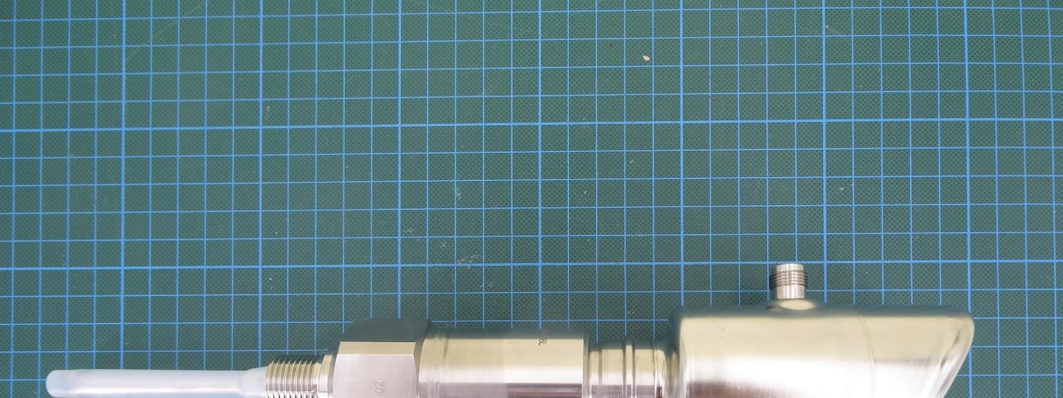
LCGFMI43
Jul 29, 2026Capacitive level sensor with BLE communication
Equipment Class
DTS - Digital Transmission System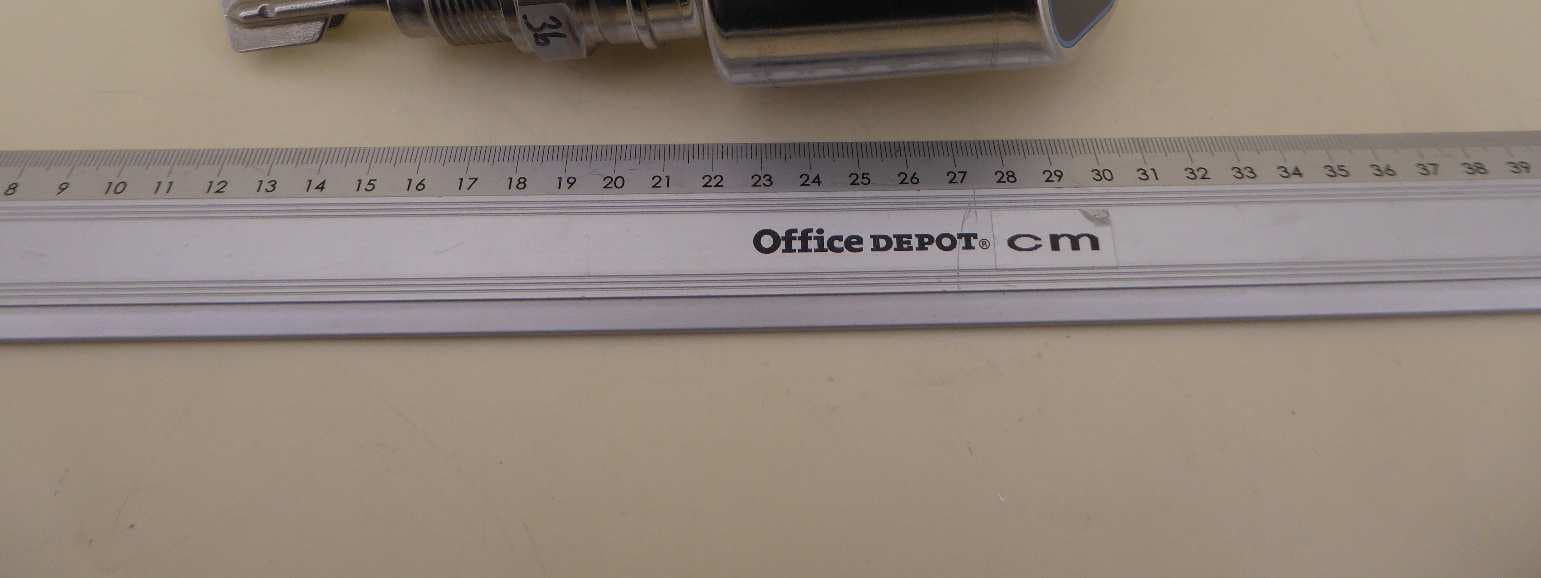
LCGFTL4X
Nov 28, 2024Hygienic point level switch for liquids with BLE TX
Equipment Class
DTS - Digital Transmission System
LCGFMR43L
Aug 07, 2024Level Probing Radar
Equipment Class
DXX - Part 15 Low Power Communication Device Transmitter
LCGUXR3XYEL
Oct 29, 2023Level Probing Radar
Equipment Class
LPR - Level Probing Radar
LCGFWR3XWEL
May 18, 2020Level Probing Radar
Equipment Class
LPR - Level Probing Radar