LGYWL261176Printer WLAN Card
Datamax-O'Neil
Click to zoom
Application Details
- Equipment Class
- DTS - Digital Transmission System
- Date of Grant
- Feb 27, 2007
- Application Purpose
- Original Equipment
- Date of Application
- Feb 27, 2007
- Equipment Note
- Printer WLAN Card
- Frequency Range
- 2412.00000000 - 2462.00000000
- Company
- Datamax-O'Neil
- Country
- United States
Documents & Files
Document Text
Text extracted from the exhibit documents filed with the FCC. Open a document above to read the original.
Users Manual
User's Guide OC-2 SERIES OF PRINTERS LP3.book Page 1 Wednesday, April 12, 2006 4:41 PM LP3.book Page 2 Wednesday, April 12, 2006 4:41 PM TA B L E O F C O N T E N T S OC-2 Printer Views 6 Front View 6 Back View 6 Right Side View 7 Left Side View 7 Setting Up Your Printer 8 Unpacking Your Printer 8 Installing Batteries 8 Removing Batteries9 Charging the Batteries9 Determining the Batteries' Condition 10 Loading Printable Media 11 Printing a Self-Test 13 Connecting the Printer 13 Installing a Data Cable13 Bluetooth and/or 802.11 b Parameters15 Configuring the Printer 15 Using the Belt Clip 16 Installing the Belt Clip 16 Removing the Belt Clip 16 Using the Control Panel 17 Audio Indicators 17 Battery Status LED 18 Power Button/LED 19 Media Function Button/LED 19 Radio Button/LED 20 Reset Button/LED 20 Using a CardReader 21 General Guidelines 21 LP3.book Page 3 Wednesday, April 12, 2006 4:41 PM TA B L E O F C O N T E N T S Using External Charging 22 Overview 22 Maintenance and Troubleshooting 23 Maintenance Guidelines 23 Preventative Maintenance 23 Troubleshooting 24 Help Desk 24 Supplies 25 For more information 25 LP3.book Page 4 Wednesday, April 12, 2006 4:41 PM LP3.book Page 5 Wednesday, April 12, 2006 4:41 PM OC-2 SERIES OF PRINTERS USER'S GUIDE 6 OC-2 Printer Views Front View Back View Figure X Figure X LP3.book Page 6 Wednesday, April 12, 2006 4:41 PM OC-2 PRINTER VIEWS 7 Right Side View Left Side View Figure X Figure X LP3.book Page 7 Wednesday, April 12, 2006 4:41 PM OC-2 SERIES OF PRINTERS USER'S GUIDE 8 Setting Up Your Printer Use the following information to set up your printer: •Unpacking Your Printer on page 8 •Installing Batteries on page 8 •Loading Printable Media on page 11 •Printing a Self-Test on page 13 •Connecting the Printer on page 13 •Configuring the Printer on page 15 In addition to the steps outlined in each section, additional information may be included if it applies to, or expands upon, the step being discussed. Unpacking Your Printer Before using the printer, remove all packaging material and inspect the printer for possible shipping damage. If the printer has been damaged: •Contact the shipping company and file a damage report. •Contact O’Neil Product Development, Inc. •Keep all shipping materials. Installing Batteries 1. Remove any packaging material (if applicable). 2. Position the battery with its contacts facing toward the battery cavity as shown in Figure X. Figure X Figure X LP3.book Page 8 Wednesday, April 12, 2006 4:41 PM SETTING UP YOUR PRINTER 9 3. Slide the battery into the battery cavity so that the edge of the battery hits the battery stop as shown in Figure X. The printer beeps one time when the first battery is installed. Do not force the battery into the battery cavity. When inserted properly, the battery easily slides and locks into place. If the battery does not easily slide into place, re- insert the battery. 4. Close the printer's cover. 5. Charge the batteries (batteries are shipped uncharged). For more information, see Charging the Batteries on page 9. Removing Batteries 1. Lift the battery up and out of the battery cavity while sliding it to the left (Figure X). 2. Remove the battery from the battery cavity. Charging the Batteries If the batteries are low when the printer turns on, the battery status LED displays red. For more information, see Using the Control Panel on page 17 . Perform the following procedure to charge the batteries: 1. Verify the battery is installed correctly. 2. Plug the AC adapter into the printer's power port (Figure X). Figure X LP3.book Page 9 Wednesday, April 12, 2006 4:41 PM OC-2 SERIES OF PRINTERS USER'S GUIDE 10 3. Plug the AC Adapter's power cord into an appropriate power source. 4. Charge the batteries. The Battery Status LED turns red while the batteries are charging and turns green when the batteries are fully charged. One complete charge takes 4 to 5 hours. Determining the Batteries' Condition The battery status LED displays the batteries' condition. When the battery status LED is solid red, the batteries must be charged; when solid orange, the batteries are at low power; when solid green, the batteries are charged. The batteries' voltage varies between 6.2 and 8.4 volts. For information on battery error conditions, see Using the Control Panel on page 17 . Power port Figure X Figure X LP3.book Page 10 Wednesday, April 12, 2006 4:41 PM SETTING UP YOUR PRINTER 11 Loading Printable Media Use the following procedure to load printable media: 1. Position the printer so that the O'Neil logo is facing you (Figure X). 2. Press and hold the printhead release button (Figure X). 3. Lift the printer's cover. 4. Place the paper roll between the metal paper roll holders as shown in Figure X. Make sure the paper exits “over” the roll and is firmly in place. 5. Unroll enough paper so that paper exits the printer (Figure X). Media Guidelines Media widthReceipt Paper: 2.25” Label Media: Roll capacity diameter Receipt Paper: 2.25” Label Media: Media typesReceipt paper media, thermal paper, hang tag stock. * Depending on the type of media used, you may need to configure your printer. For more information, see Configuring the Printer on page 15. Figure X Figure X LP3.book Page 11 Wednesday, April 12, 2006 4:41 PM OC-2 SERIES OF PRINTERS USER'S GUIDE 12 6. Close the printer's printhead cover. The printer's printhead cover “snaps” into place when completely closed. 7. Verify the media exits straight. 8. Push the Media Function button one time to advance the media (Figure X). 9. At either edge of the printer's printhead cover are serrated corners. Tear the media by pulling up and away from the printer's (Figure X). Warning: The tear bar and printhead cover's surface may be hot and/or sharp. Use caution when handling the printhead and tear bar. Figure X Figure X Figure X Figure X Figure X LP3.book Page 12 Wednesday, April 12, 2006 4:41 PM SETTING UP YOUR PRINTER 13 Printing a Self-Test 1. Press and hold the power button for approxi…
Text truncated - open the document above for the full version.
Cover Letter(s)
114 OLINDA DRIVE • •• • BREA, CALIFORNIA 92823 • •• • (714) 579-0500 • •• • FAX (714) 579-1850 January 24, 2007 RE: O’Neil Product Development, Inc. FCC: LGYWL261176 1) For the model LP3-L, it does not appear that the back of the unit that would typically be positioned against the body was actually tested. Additionally, it is uncertain exactly where the board/antenna is located even though the photos show some of this information. Response: The LP3-L was tested in the worst case (Printer turned 90 degrees with antenna as close to the body. Additional photos of the LP3-L are also attached. 2) For the model OC2-L, it is uncertain how this device will normally be positioned body worn. Please provide further detail. Response: Please see the Additional Photos for how the unit will be body worn. 3) Please provide sufficient information to show how each unit would normally be body worn, compared to how the device was tested for SAR. Response: Please see the Additional Photos showing how the devices were tested for SAR and how each unit would normally be body worn. 4) From the manual, it is not clear what body worn accessories are for use with each printer (straps, belt clips, holsters, etc.) Response: Please see the Additional Photos 5) Typically the manual would explain RF exposure information to the user (i.e. proper positioning, meeting FCC RF exposure requirements, etc.). Response: The RF exposure Information is on page 27 as part of the FCC Notice. The Owner’s Manual has been resent to highlight the RF exposure information. 114 OLINDA DRIVE • •• • BREA, CALIFORNIA 92823 • •• • (714) 579-0500 • •• • FAX (714) 579-1850 6) SAR reports reference 15E for FCC. This appears incorrect. Response: This has been Revised to say 15 Subpart C; Section 15.247 7) Even thought the SAR power is expected to be >= EMC power, it is expected to be within 0.5 dB. 802.11 g maximum power appears > 0.5 dB. Please review. Response: The test levels are within 0.5 dB of the 802.11 g maximum power. Please note that the power output were done on each individual channel and each individual channel is within 0.5 dB (and also >=) of the EMC test report Also, the first page of each SAR test report has been revised to correctly state the maximum power for 802.11 g. The EMC test report also has the output power taken for each channel. 8) Please explain where the SAR report explains: a) The probe tip distance to phantom inner surface b) The first 2 measurements points in a zoom scan, closest to the phantom surface, should be within 1 cm of the surface. c) Distance between the measurement point (distance + offset) at the probe sensor location (geometric center behind the probe tip) and the phantom surface is < 8.0 mm and maintained at a constant distance of +/- 1.0 mm during an area scan to determine peak SAR locations Response: (from SAR Test Lab) The #8a is located in the probe calibration report on the third page of the report. #8b. The first measurement is conducted with the sensor (offset + position) 5 mm from the phantom. The second measurement is conduct with the sensor (offset + position) 10 mm from the phantom. #8c. During the area scan, the test is conducted with the tip of the probe 5 mm from the phantom. The offset of the probe is 1.56 mm which give you a distance of 6.56 mm from the phantom. The tolerance of the robot arm is +/- 0.05 mm.
ID Label/Location Info
LP3 802.11 b/g Made in USA Part No. Serial No. LA00100 with FCC Standards FOR HOME OR OFFICE USE Tested to Comply 200271-100 Contains FCC ID: LGYWL261176 IC: 2640A-WL261176 Contains radio device WL261176 Tested to Comply with FCC Standards Part No. Serial No. FOR HOME OR OFFICE USE MF2T 802.11 b/g TA00101 Made in USA 200263-100 Contains FCC ID: LGYWL261176 IC: 2640A-WL261176 Contains radio device WL261176 Made in USA Part No. Serial No.MA00100 MF4T 802.11 b/g 200290-100 with FCC Standards FOR HOME OR OFFICE USE Tested to Comply Contains FCC ID: LGYWL261176 IC: 2640A-WL261176 Contains radio device WL261176 Part No. Serial No. OC-2 802.11b/g LI00101 Made in USA 200326-100 with FCC Standards FOR HOME OR OFFICE USE Tested to Comply Contains FCC ID: LGYWL261176 IC: 2640A-WL261176 Contains radio device WL261176
RF Exposure Info
© 2006 RF Exposure Lab, LLC This report shall not be reproduced except in full without the written approval of RF Exposure Lab, LLC. 2867 Progress Place, Suite 4D • Escondido, CA 92029 • U.S.A. TEL (760) 737-3131 • FAX (760) 737-9131 http://www.rfexposurelab.com CERTIFICATE OF COMPLIANCE SAR EVALUATION O’Neil Product Development, Inc. Dates of Test: Nov. 28, 2006 8 Mason Test Report Number: SAR.20061114 Irvine, CA 92618 Revision B This wireless mobile and/or portable device has been shown to be compliant for localized specific absorption rate (SAR) for uncontrolled environment/general exposure limits specified in ANSI/IEEE Std. C95.1-1999 and had been tested in accordance with the measurement procedures specified in IEEE 1528-2003, OET Bulletin 65 Supp. C, RSS-102 and Safety Code 6 (See test report). I attest to the accuracy of the data. All measurements were performed by myself or were made under my supervision and are correct to the best of my knowledge and belief. I assume full responsibility for the completeness of these measurements and vouch for the qualifications of all persons taking them. RF Exposure Lab, LLC certifies that no party to this application has been denied FCC benefits pursuant to Section 5301 of the Anti-Drug Abuse Act of 1988, 21 U.S.C. 853(a). Jay M. Moulton Vice President Certificate # 2387.01 FCC ID: LGYWL261176 IC Certificate: 2640-WL261176 Model(s): OC2-L_802.11 Test Sample: Engineering Unit same as Production Serial No.: Eng 1 Equipment Type: Wireless Printer Classification: Portable Transmitter Next to Body TX Frequency Range: 2412 – 2462 MHz Frequency Tolerance: ± 25 ppm Maximum RF Output: 2412–2462 MHz, (b)16. 90 dBm, (g)21.26 dBm Conducted Signal Modulation: DSSS, OFDM Antenna Type (Length): Internal(O’Neil Pro. Dev., PCB Design-Antenna_LEG-E) Battery: Std. (Totex P/N 550039-100) Battery Pack Application Type: Certification FCC Rule Parts: Part 15 C, Se. 15.247 Industry Canada: RSS-102, Safety Code 6 FCC ID: LGYWL261176 © 2006 RF Exposure Lab, LLC Page 2 of 67 This report shall not be reproduced except in full without the written approval of RF Exposure Lab, LLC. Table of Contents 1. Introduction ...........................................................................................................................3 SAR Definition [5]......................................................................................................................3 2. SAR Measurement Setup .....................................................................................................4 Robotic System .........................................................................................................................4 System Hardware .....................................................................................................................4 System Description ...................................................................................................................4 E-Field Probe ALS-E-020 ......................................................................................................... 5 3. Robot Specifications .............................................................................................................7 4. Probe and Dipole Calibration ................................................................................................8 5. Phantom & Simulating Tissue Specifications........................................................................9 SAM Phantom ...........................................................................................................................9 Brain & Muscle Simulating Mixture Characterization ................................................................9 Device Holder ...........................................................................................................................9 6. Definition of Reference Points.............................................................................................10 Ear Reference Point................................................................................................................10 Device Reference Points ........................................................................................................10 7. Test Configuration Positions ...............................................................................................11 Positioning for Cheek/Touch [5] ..............................................................................................11 Positioning for Ear / 15 ̊ Tilt [5]................................................................................................12 Body Worn Configurations ......................................................................................................13 8. ANSI/IEEE C95.1 – 1999 RF Exposure Limits [2]...............................................................14 Uncontrolled Environment.......................................................................................................14 Controlled Environment .......................................................................................................... 14 9. Measurement Uncertainty ...................................................................................................15 10. System Validation ........................................................................................................... 16 Tissue Verification...................................................................................................................16 Test System Verification ......................................................................................................... 16 11. SAR Test Data Summary ................................................................................................17 Procedures Used To Establish Test Signal.............................................................................17 Device Test Condition ..............................…
Text truncated - open the document above for the full version.
RF Exposure Info
© 2006 RF Exposure Lab, LLC This report shall not be reproduced except in full without the written approval of RF Exposure Lab, LLC. 2867 Progress Place, Suite 4D • Escondido, CA 92029 • U.S.A. TEL (760) 737-3131 • FAX (760) 737-9131 http://www.rfexposurelab.com CERTIFICATE OF COMPLIANCE SAR EVALUATION O’Neil Product Development, Inc. Dates of Test: Nov. 28, 2006 8 Mason Test Report Number: SAR.20061116 Irvine, CA 92618 Revision C This wireless mobile and/or portable device has been shown to be compliant for localized specific absorption rate (SAR) for uncontrolled environment/general exposure limits specified in ANSI/IEEE Std. C95.1-1999 and had been tested in accordance with the measurement procedures specified in IEEE 1528-2003, OET Bulletin 65 Supp. C, RSS-102 and Safety Code 6 (See test report). I attest to the accuracy of the data. All measurements were performed by myself or were made under my supervision and are correct to the best of my knowledge and belief. I assume full responsibility for the completeness of these measurements and vouch for the qualifications of all persons taking them. RF Exposure Lab, LLC certifies that no party to this application has been denied FCC benefits pursuant to Section 5301 of the Anti-Drug Abuse Act of 1988, 21 U.S.C. 853(a). Jay M. Moulton Vice President Certificate # 2387.01 FCC ID: LGYWL261176 IC Certificate: 2640-WL261176 Model(s): LP3-L_802.11 Test Sample: Engineering Unit same as Production Serial No.: Eng 1 Equipment Type: Wireless Printer Classification: Portable Transmitter Next to Body TX Frequency Range: 2412 – 2462 MHz Frequency Tolerance: ± 25 ppm Maximum RF Output: 2412–2462 MHz, (b)16. 90 dBm, (g)21.26 dBm Conducted Signal Modulation: DSSS, OFDM Antenna Type (Length): Internal(O’Neil Pro. Dev., PCB Design-Antenna_LEG-B) Battery: Std. (Totex P/N 550039-100) Battery Pack Application Type: Certification FCC Rule Parts: Part 15 , Sec. 15.247 Industry Canada: RSS-102, Safety Code 6 FCC ID: LGYWL261176 © 2006 RF Exposure Lab, LLC Page 2 of 67 This report shall not be reproduced except in full without the written approval of RF Exposure Lab, LLC. Table of Contents 1. Introduction ...........................................................................................................................3 SAR Definition [5]......................................................................................................................3 2. SAR Measurement Setup .....................................................................................................4 Robotic System .........................................................................................................................4 System Hardware .....................................................................................................................4 System Description ...................................................................................................................4 E-Field Probe ALS-E-020 ......................................................................................................... 5 3. Robot Specifications .............................................................................................................7 4. Probe and Dipole Calibration ................................................................................................8 5. Phantom & Simulating Tissue Specifications........................................................................9 SAM Phantom ...........................................................................................................................9 Brain & Muscle Simulating Mixture Characterization ................................................................9 Device Holder ...........................................................................................................................9 6. Definition of Reference Points.............................................................................................10 Ear Reference Point................................................................................................................10 Device Reference Points ........................................................................................................10 7. Test Configuration Positions ...............................................................................................11 Positioning for Cheek/Touch [5] ..............................................................................................11 Positioning for Ear / 15 ̊ Tilt [5]................................................................................................12 Body Worn Configurations ......................................................................................................13 8. ANSI/IEEE C95.1 – 1999 RF Exposure Limits [2]...............................................................14 Uncontrolled Environment.......................................................................................................14 Controlled Environment .......................................................................................................... 14 9. Measurement Uncertainty ...................................................................................................15 10. System Validation ........................................................................................................... 16 Tissue Verification...................................................................................................................16 Test System Verification ......................................................................................................... 16 11. SAR Test Data Summary ................................................................................................17 Procedures Used To Establish Test Signal.............................................................................17 Device Test Condition ..............................…
Text truncated - open the document above for the full version.
RF Exposure Info
© 2006 RF Exposure Lab, LLC This report shall not be reproduced except in full without the written approval of RF Exposure Lab, LLC. 2867 Progress Place, Suite 4D • Escondido, CA 92029 • U.S.A. TEL (760) 737-3131 • FAX (760) 737-9131 http://www.rfexposurelab.com CERTIFICATE OF COMPLIANCE SAR EVALUATION O’Neil Product Development, Inc. Dates of Test: Nov. 28, 2006 8 Mason Test Report Number: SAR.20061110 Irvine, CA 92618 Revision C This wireless mobile and/or portable device has been shown to be compliant for localized specific absorption rate (SAR) for uncontrolled environment/general exposure limits specified in ANSI/IEEE Std. C95.1-1999 and had been tested in accordance with the measurement procedures specified in IEEE 1528-2003, OET Bulletin 65 Supp. C, RSS-102 and Safety Code 6 (See test report). I attest to the accuracy of the data. All measurements were performed by myself or were made under my supervision and are correct to the best of my knowledge and belief. I assume full responsibility for the completeness of these measurements and vouch for the qualifications of all persons taking them. RF Exposure Lab, LLC certifies that no party to this application has been denied FCC benefits pursuant to Section 5301 of the Anti-Drug Abuse Act of 1988, 21 U.S.C. 853(a). Jay M. Moulton Vice President Certificate # 2387.01 FCC ID: LGYWL261176 IC Certificate: 2640-WL261176 Model(s): MF2T-L_802.11 Test Sample: Engineering Unit same as Production Serial No.: Eng 1 Equipment Type: Wireless Printer Classification: Portable Transmitter Next to Body TX Frequency Range: 2412 – 2462 MHz Frequency Tolerance: ± 25 ppm Maximum RF Output: 2412–2462 MHz, (b)16. 90 dBm, (g)21.28 dBm Conducted Signal Modulation: DSSS, OFDM Antenna Type (Length): Internal(O’Neil Pro. Dev., PCB Design-Antenna_LEG-C2) Battery: Std. (Totex P/N 550041-100) Battery Pack Application Type: Certification FCC Rule Parts: Part 15 C, Sec. 15.247 Industry Canada: RSS-102, Safety Code 6 FCC ID: LGYWL261176 © 2006 RF Exposure Lab, LLC Page 2 of 68 This report shall not be reproduced except in full without the written approval of RF Exposure Lab, LLC. Table of Contents 1. Introduction ...........................................................................................................................3 SAR Definition [5]......................................................................................................................3 2. SAR Measurement Setup .....................................................................................................4 Robotic System .........................................................................................................................4 System Hardware .....................................................................................................................4 System Description ...................................................................................................................4 E-Field Probe ALS-E-020 ......................................................................................................... 5 3. Robot Specifications .............................................................................................................7 4. Probe and Dipole Calibration ................................................................................................8 5. Phantom & Simulating Tissue Specifications........................................................................9 SAM Phantom ...........................................................................................................................9 Brain & Muscle Simulating Mixture Characterization ................................................................9 Device Holder ...........................................................................................................................9 6. Definition of Reference Points.............................................................................................10 Ear Reference Point................................................................................................................10 Device Reference Points ........................................................................................................10 7. Test Configuration Positions ...............................................................................................11 Positioning for Cheek/Touch [5] ..............................................................................................11 Positioning for Ear / 15 ̊ Tilt [5]................................................................................................12 Body Worn Configurations ......................................................................................................13 8. ANSI/IEEE C95.1 – 1999 RF Exposure Limits [2]...............................................................14 Uncontrolled Environment.......................................................................................................14 Controlled Environment .......................................................................................................... 14 9. Measurement Uncertainty ...................................................................................................15 10. System Validation ........................................................................................................... 16 Tissue Verification...................................................................................................................16 Test System Verification ......................................................................................................... 16 11. SAR Test Data Summary ................................................................................................17 Procedures Used To Establish Test Signal.............................................................................17 Device Test Condition ...........................…
Text truncated - open the document above for the full version.
RF Exposure Info
© 2006 RF Exposure Lab, LLC This report shall not be reproduced except in full without the written approval of RF Exposure Lab, LLC. 2867 Progress Place, Suite 4D • Escondido, CA 92029 • U.S.A. TEL (760) 737-3131 • FAX (760) 737-9131 http://www.rfexposurelab.com CERTIFICATE OF COMPLIANCE SAR EVALUATION O’Neil Product Development, Inc. Dates of Test: Nov. 28, 2006 8 Mason Test Report Number: SAR.20061112 Irvine, CA 92618 Revision B This wireless mobile and/or portable device has been shown to be compliant for localized specific absorption rate (SAR) for uncontrolled environment/general exposure limits specified in ANSI/IEEE Std. C95.1-1999 and had been tested in accordance with the measurement procedures specified in IEEE 1528-2003, OET Bulletin 65 Supp. C, RSS-102 and Safety Code 6 (See test report). I attest to the accuracy of the data. All measurements were performed by myself or were made under my supervision and are correct to the best of my knowledge and belief. I assume full responsibility for the completeness of these measurements and vouch for the qualifications of all persons taking them. RF Exposure Lab, LLC certifies that no party to this application has been denied FCC benefits pursuant to Section 5301 of the Anti-Drug Abuse Act of 1988, 21 U.S.C. 853(a). Jay M. Moulton Vice President Certificate # 2387.01 FCC ID: LGYWL261176 IC Certificate: 2640-WL261176 Model(s): MF4T-L_802.11 Test Sample: Engineering Unit same as Production Serial No.: Eng 1 Equipment Type: Wireless Printer Classification: Portable Transmitter Next to Body TX Frequency Range: 2412 – 2462 MHz Frequency Tolerance: ± 25 ppm Maximum RF Output: 2412–2462 MHz, (b)16. 90 dBm, (g)21.27 dBm Conducted Signal Modulation: DSSS, OFDM Antenna Type (Length): Internal(O’Neil Pro. Dev., PCB Design-Antenna_LEG-C2) Batt…
Text truncated - open the document above for the full version.
Contact Information
Applicant
Endre Vargha(Vice President Engineering)
Technical Contact
Compatible ElectronicsKyle Fujimoto
[email protected]714 579 0500
114 Olinda Drive · Brea · United States
Test Firm
Compatible Electronics, Inc.Michael Christensen
Technical Specifications
| # | Rule Parts | Frequency Range | Power Output |
|---|---|---|---|
| 1 | 15C | 2.41 GHz - 2.46 GHz | 133.00 mW |
Other Applications from Datamax-O'Neil
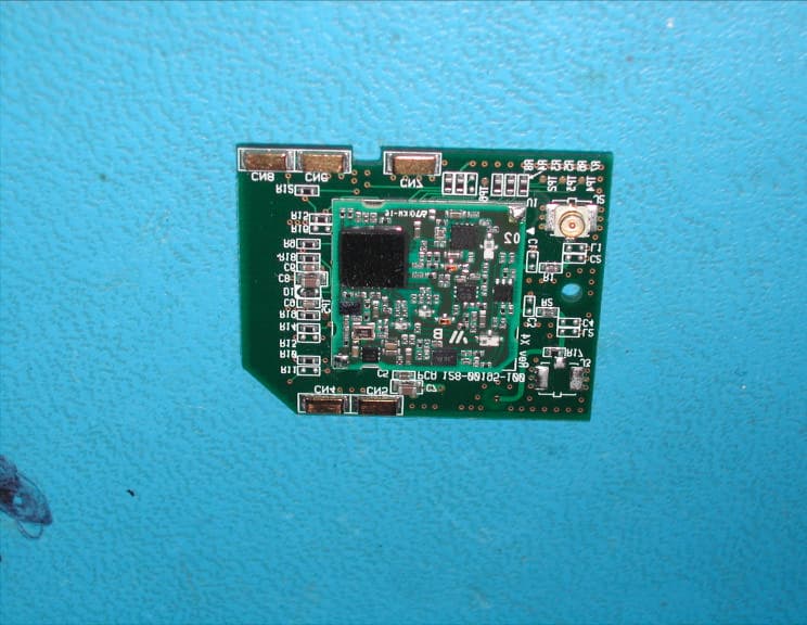
LGYWL430220
Oct 07, 2010Wireless Printer Module
Equipment Class
DTS - Digital Transmission System
LGYBT261159P
Feb 05, 2007Radio Bluetooth Unicellular
Equipment Class
DSS - Part 15 Spread Spectrum Transmitter
LGYBT261159
May 17, 2006Bluetooth Module
Equipment Class
DSS - Part 15 Spread Spectrum Transmitter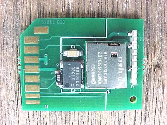
LGYBT260146
Apr 15, 2004Bluetooth Module
Equipment Class
DSS - Part 15 Spread Spectrum Transmitter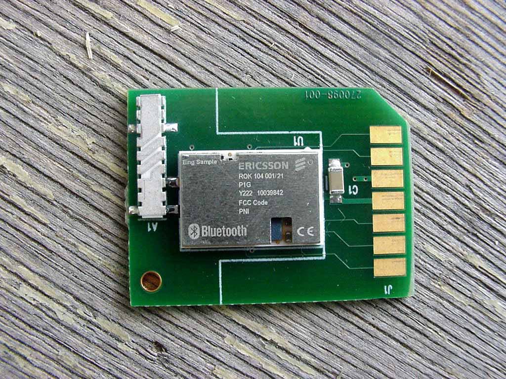
LGYBT260136
Jan 15, 2003Bluetooth Module
Equipment Class
DSS - Part 15 Spread Spectrum Transmitter